

Electrolux Gl44ngdc, Gl44hongdc, Gl44lpdc, Gl44holpdc Owner's Manual
Lighting the Grill ..................... 13
Care & MaintenanGe ...............16
Before You Call
T_oub_e Shoot_ng .............17-18
@
Vidt the Rrigidaire Web Site at:
READ AND SAVE THESE INSTRUCTIONS - MADE IN THE U.SoAo
Wsrrant_ ......................... 19
Congratulations on your purchase of a new gas grill! At Electrolux Home Products, we
are very proud of our product and are completely committed to providing you with the
best service possible. Your satisfaction is our number one priority.
We know you'll enjoy your new gas grill and Thank You for choosing our product. We
hope you consider us for future purchases.
PLEASE CAREFULLY READ AND SAVE THESE INSTRUCTIONS
This Use & Care Manual provides specific operating instruction for your model. Use your
gas grill only as instructed in this manual. These instructions are not meant to cover every
possible condition and situation that may occur. Common sense and caution must be
practiced when installing, operating and maintaining any appliance.
Questions? 1-800-320-0859
Please record Grill information for future reference and service work:
Model #:
Serial #:
Date of Purchase:
Gas Type:
Please retain this manual for future reference
6) 2004 Electrolux ttome Products, lnc All rights reserved
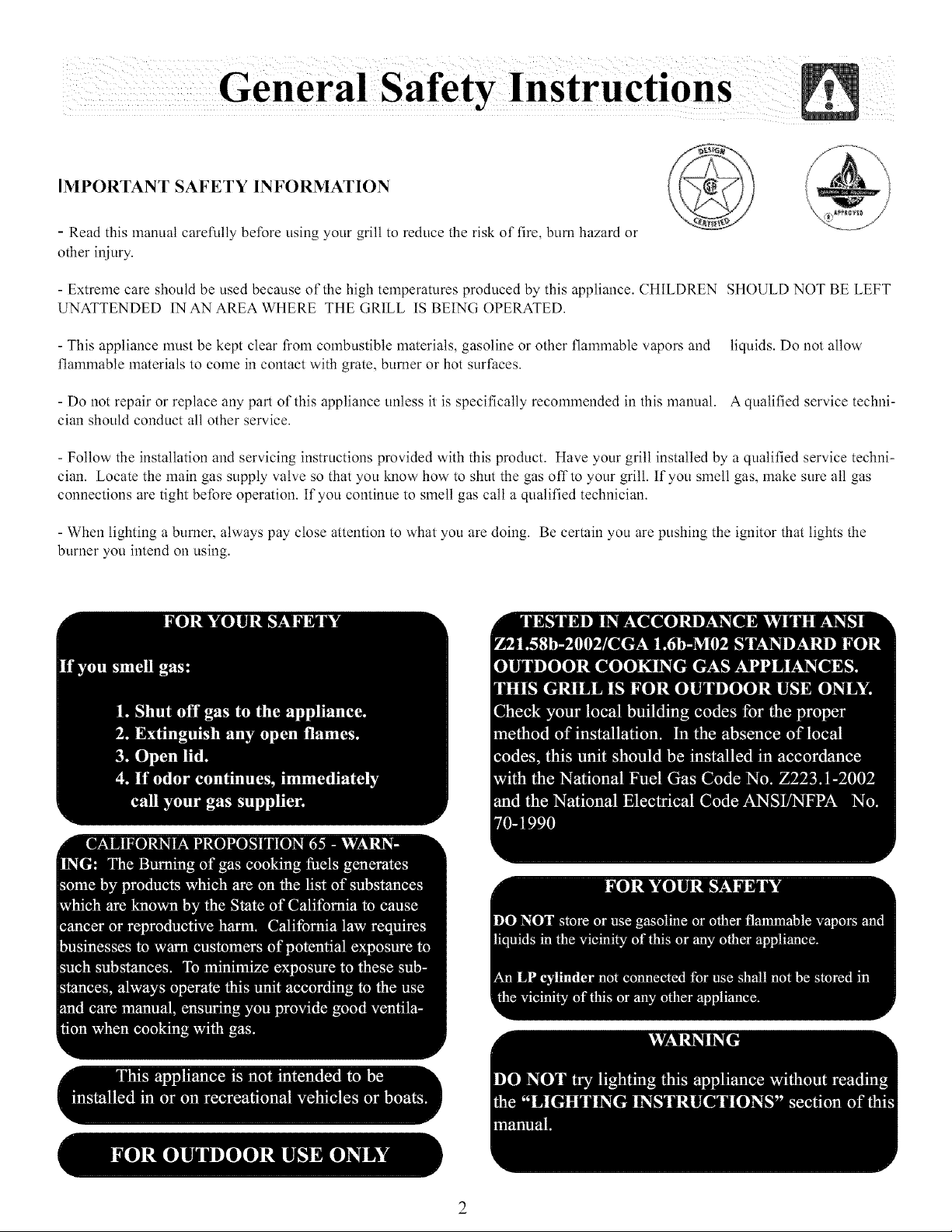
IMPORTANT SAFETY INFORMATION
- Read this manual carefully before using your grill to reduce the risk of fil_, bum hazard or
other injury.
- Extreme cam should be used because of the high telnperatures produced by this appliance. CHILDREN SHOULD NOT BE LEFT
UNATTENDED IN AN AREA WHERE THE ()RILL IS BEING OPERATED.
- This appliance must be kept clear from combustible materials, gasoline or other flammable vapors and liquids. Do not allow
flalmnable materials to come in contact with grate, burner or hot surfaces.
- Do not repair or replace any part of this appliance unless it is specifically recommended in this manual. A qualified service techni-
cian should conduct all other service.
- Follow the installation and servicing instructions provided with this product. Have your grill installed by a qualified service techni-
cian. Locate the main gas supply valve so that you know how to shut the gas off to your grill. If you smell gas, make sum all gas
connections are tight before operation. If you continue to smell gas call a qualified technician.
- When lighting a burner, always pay close attention to what you am doing. Be certain you are pushing the ignitor that lights the
burner you intend on using.
2
13
9
10
14
5
12
5
11
.
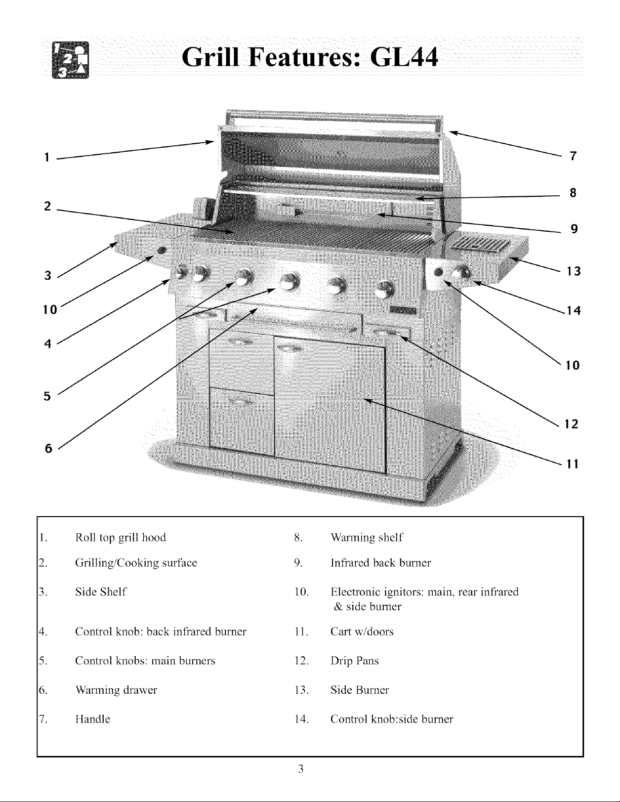
Roll top grill hood
2.
3.
Grilling/Cooking surface
Side Shelf
9.
10.
.
Warming shelf
Infrared back burner
Electronic ignitors: main, rear infrared
& side burner
Control knob: back infrared burner
.
Control knobs: main burners
5.
7.
Warming drawer
tlandle
11.
12.
13.
14.
Cart w/doors
Drip Pans
Side Burner
Control knob:side burner
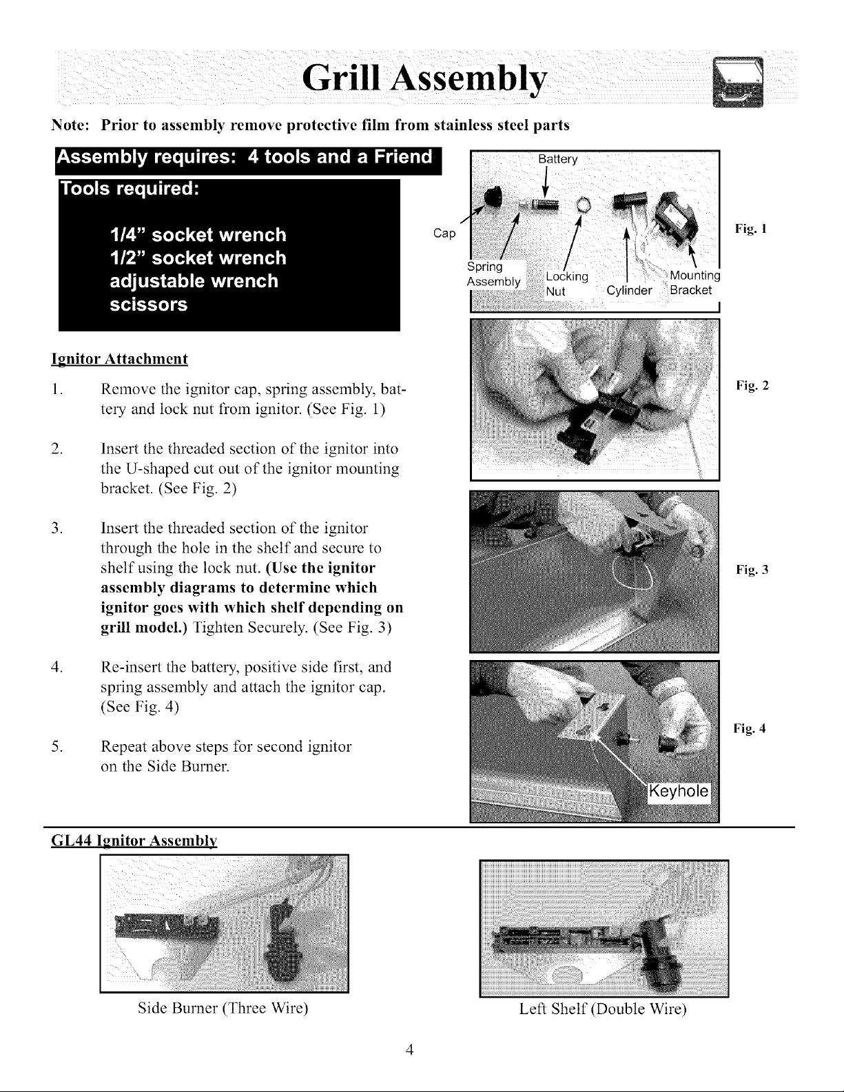
Note: Prior to assembly remove protective film from stainless steel parts
Battery:r i_ ii I
Ignitor Attachment
1. Remove the ignitor cap, spring assembly, bat-
tery and lock nut from ignitor. (See Fig. 1)
.
Insert the threaded section of the ignitor into
the U-shaped cut out of the ignitor mounting
bracket. (See Fig. 2)
.
Insert the threaded section of the ignitor
through the hole in the shelf and secure to
shelf using the lock nut. (Use the ignitor
assembly diagrams to determine which
ignitor goes with which shelf depending on
grill model.) Tighten Securely. (See Fig. 3)
Cap
Spring
Assembly
Nut Cylinder Bracket
i
Fig. 1
I
Fig. 2
Fig. 3
.
Re-insert the battery, positive side first, and
spring assembly and attach the ignitor cap.
(See Fig. 4)
.
Repeat above steps for second ignitor
on the Side Burner.
GL44 Ignitor Assembly
Side Burner (Three Wire)
Fig. 4
Left Shelf (Double Wire)
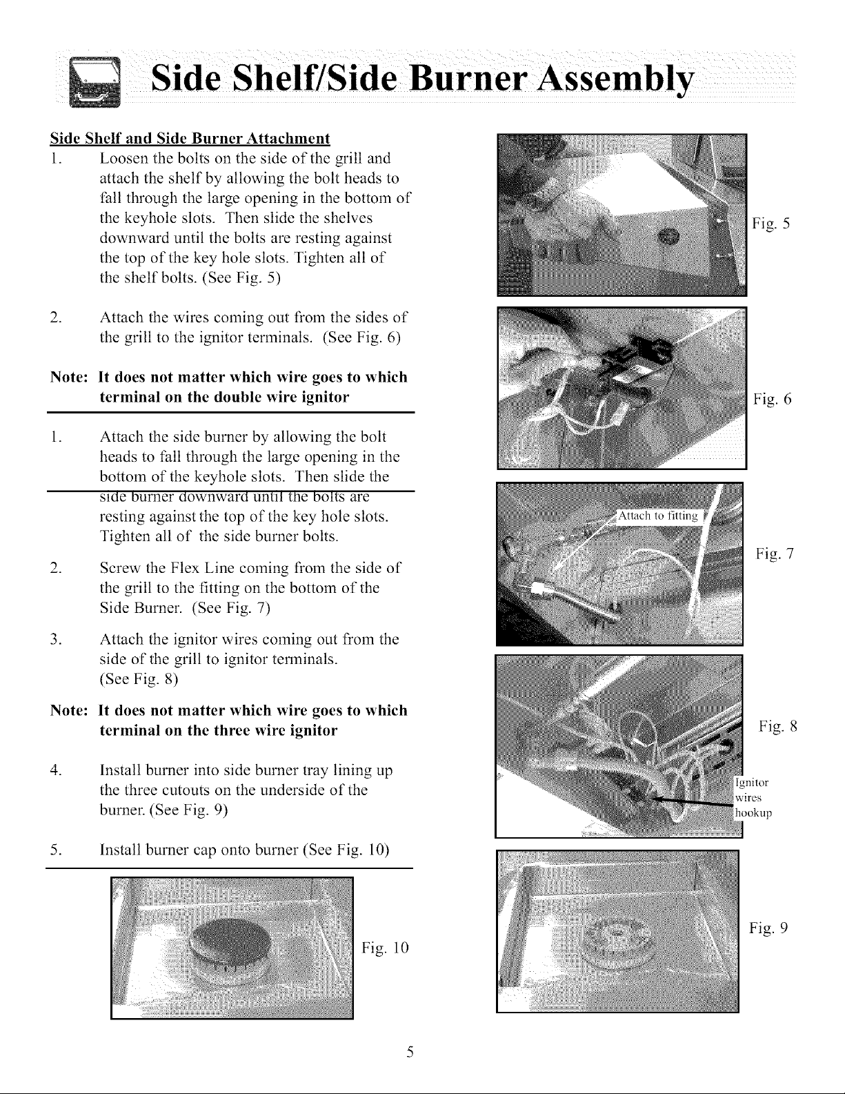
Side Shelf and Side Burner Attachment
1. Loosen the bolts on the side of'the grill and
attach the shell" by allowing the bolt heads to
fall through the large opening in the bottom of"
the keyhole slots. Then slide the shelves
downward until the bolts are resting against
the top of'the key hole slots. Tighten all of"
the shell" bolts. (See Fig. 5)
.
Attach the wires coming out from the sides of
the grill to the ignitor terminals. (See Fig. 6)
Note: It does not matter which wire goes to which
terminal on the double wire ignitor
.
Attach the side burner by allowing the bolt
heads to fall through the large opening in the
bottom of the keyhole slots. Then slide the
sine burner aownwara until me boltS are
resting against the top of the key hole slots.
Tighten all of the side burner bolts.
.
Screw the Flex Line coming from the side of
the grill to the fitting on the bottom of the
Side Burner. (See Fig. 7)
Fig. 5
Fig. 6
Fig. 7
.
Attach the ignitor wires coming out from the
side of the grill to ignitor terminals.
(See Fig. 8)
Note:
It does not matter which wire goes to which
terminal on the three wire ignitor
.
Install burner into side burner tray lining up
the three cutouts on the underside of the
burner. (See Fig. 9)
5. Install burner cap onto burner (See Fig. 10)
Fig. 10
Fig. 8
wires
hookup
Fig. 9
 Loading...