

Page 1
Thermetic
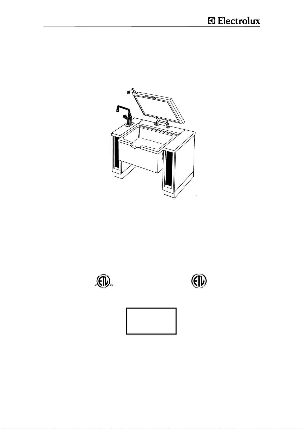
TILTING FRYING PANS, RECTANGLE, ELECTRIC
(GP........)
US SERVICE MANUAL
Electrically and steam heated
TILTING FRYING PANS
Doc. 62.9694.03
Edition 1
09.2006
Page 2
CONTENTS
1. CONSTRUCTION/ FUNCTIONS......................................................................................... 3
1.1 TECHNICAL DATA 3
2. ELECTRIC DIAGRAMS ...................................................................................................... 4
3. MAINTENANCE CHECK LIST............................................................................................ 6
4. ACCESS TO INSIDE........................................................................................................... 7
5. FUNCTIONAL COMPONENTS.............. .... ... ... ... ... .... ... ... ... .... ............................................ 7
5.1 FU1. OPERATING FOIL ................................................................ .................................... ...............7
5.2 FU2. UNIVERSAL CONTROL .................. ... .................................... ... ... .................................... ....... 8
5.2.1 PARAMETER PROGRAMMING ....................................................................................................................... 8
5.2.2 MANUAL PARAMETER INPUT ........................................................................................................................ 8
5.2.3 PROGRAMMING SPECIFIC APPLIANCE AND USER DATA ........................................................................ 9
5.2.4 TRIMMING OF TEMPERATURE MEASURING ............................................................................................. 11
5.2.5 TEST FUNCTIONS FOR SERVICE APPLICATION ....................................................................................... 11
5.2.6 TROUBLESHOOTING DISPLAY .................................................................................................................... 12
5.2.7 OPERATING PRINT (UP) ............................................................................................................................... 12
5.2.8 CONTROL PRINT (SP) .............................................................. ..................... ................................................ 13
5.2.9 CONTROL SWITCH (S) ............................................................. ..................... ................................................ 13
5.2.10 SAFETY THERMOSTAT (F1) ......................................................................................................................... 14
5.2.11 FOOD SENSOR (B1) ...................................................................................................................................... 14
5.2.12 ELECTRIC HEATING (EI, EA) ........................................................................................................................ 15
5.2.13 END SWITCH (ES) .......................................................................................................................................... 15
5.2.14 TERMINALS .................................................................................................................................................... 16
5.2.15 CONTROL FUSE (X4) ..................................................................................................................................... 16
5.2.16 CONTACTORS (K) ......................................................................................................................................... 16
5.2.17 HEATING RESISTOR (E11) ........................................................................................................................... 16
5.2.18 POWER ISOLATOR (H) .................................................................................................................................. 16
5.3 FU1.3. MOTOR TILTING ...............................................................................................................17
5.3.1 CONTROL SYSTEM (KS) ............................................................................................................................... 17
5.3.2 TILTING MOTOR (AN) .................................................................................................................................... 17
5.3.3 SWITCH (CK) .................................................................................................................................................. 17
5.4 LID (D) ............................................................................................................................................. 19
5.4.1 LID HINGE (DG) .............................................................................................................................................. 19
62.9692.03 Page 1
Page 3

5.5 MIXING UNIT ................................................................................................................................... 20
5.6 PAN .................................................................................................................................................21
5.6.1 BEARINGS, PIVOTS .......................................................................................................................................21
5.6.2 CASING (MN) ..................................................................................................................................................21
5.7 APPENDIX
UNIVERSAL CONTROL DESCRIPTION OF PARAMETERS .....................................................22
Page 2 62.9692.03
Page 4
VALIDITY
This document refers to the following tilting frying pans:
Tilting frying pans,
electrically heated
.P.B......
060 E
(15.9 gal)
.P.C......
080 E
(21.1 gal)
.P.E......
100 E
(26.4 gal)
ADDITIONAL DOCUMENTS
Operating instructions 76.9694.01 delivered with the appli-
ance
Installation instructions76.9698 delivered with the appliance
Spare parts list 76.9694.02 distributed by the service
department
Electrical diagrams 91.2046, 91.2048, delivered with the
appliance
SERIAL NUMBER YWWXXXXX
The serial number of the appliance is marked on the type
plate. The 8 digits give following information:
Y last digit of the year of production
WW week of production
XXXXX running number
SAFETY MEASURES
• Maintenance work, adjustments, conversions and repairs
may only be carried out by an authorized technician. These
technicians must be instructed by the manufacturer and
carry out the work in accordance with specific national and
local regulations. Parts requiring replacement are only to
be replaced by original spares.
• Follow strictly the attention and warning label indications
on the appliances.
• Cleaning and maintenance may only be carried ou t when
the appliance is cold.
• In case a connection with a sealing is opened, always a
new sealing should be used when installing the connection.
• The manager is responsible for ensuring that all compo-
nents relevant for safety (jacket safety valve, drain valve,
pressure gauge, thermostat, excess-temperature thermostat) are in perfect working order at all times. The operating
condition of these components must be examined by an
authorized technician at least once a year and any defects
remedied if required.
• Before beginning any servicing, all appliances must be dis-
connected from the power supply; the steam, condensate,
hot water and drinking water pipes must also be turned off
or closed. Disconnection from the power supply is effected
by switching off at the main switch or removing the fuses
fitted to the power supply.
• The internal wiring in the appliance as well as the earth
connections must be carried out in accordance with the
complete electrical schematic. Basically, all metal parts on
which electrical connections are located must be earthed.
• Boiling pans of this design and operating function do not
require special acceptance tests. They are subjected to a
pressure and operating test which meets the regulations on
the manufacturer's premises. Recurrent pressure testing is
not compulsory. To ensure the complete operating efficiency and safety of appliances, however, owners should
arrange for personnel authorized by the manufacturer to
check on all safety equipment and to conduct pressure
tests at regular intervals.
• After the appliance has been connected up, the service
agent must carry out a test of all functions in the course of
which all the programs and operating states of all operating
elements as laid down in the operating instructions are
checked.
• The conclusion of a maintenance agreement should be
recommended to the user.
MAINTENANCE INTERVAL
An obligatory service check is required annually.
1. CONSTRUCTION/ FUNCTIONS
The food is heated by the thick base of the pan under which
several electric rod heaters are located. The pans are
equipped with an electronic comfort control unit with regulation
of the bottom resp. food temperature with or without programming of the cooking time and starting time. The control system
is operated via a membrane keyboard. The pan has a variablespeed tilting facility powered by an electric motor. All types can
be fitted with a mixing unit if required.
1.1 TECHNICAL DATA
Pan bottom made of steel or nickel-chrome plated steel.
Floor mounting on feets or wheels.
Electronic control of pan-base and cooking temperature
or process control system of pan-base and cooking tempera-
ture regulation with programmable cooking and starting time
Hoseproof IP X5
Heating up times (see schedule) of an empty pan from 68°F
(20°C) to an average bottom temperature of 446°F (230°C)
.
Electrically heated tilting frying pans
GP.B......
060 E
(15.9 gal)
Wattage kW 12,2 15,2 18,2
Voltage 208V/3~N
Current A
Voltage 240V/3~N
Current A
Voltage 480V/3~N
Current A
Net content in lt (=max.
capacity)
Heating up times, min. 20 20 20
El. tilting motor: Wattage
kWVoltageCurrent A
35.5 31 15.7
43.8 38.1 19.8
43.8 38.1 23
63 84 104
0.2
230V/1*NE, 50 Hz
1
GP.C......
080 E
(21.1 gal)
GP.E......
100 E
(26.4 gal)
62.9694.03 Page 3
Page 5
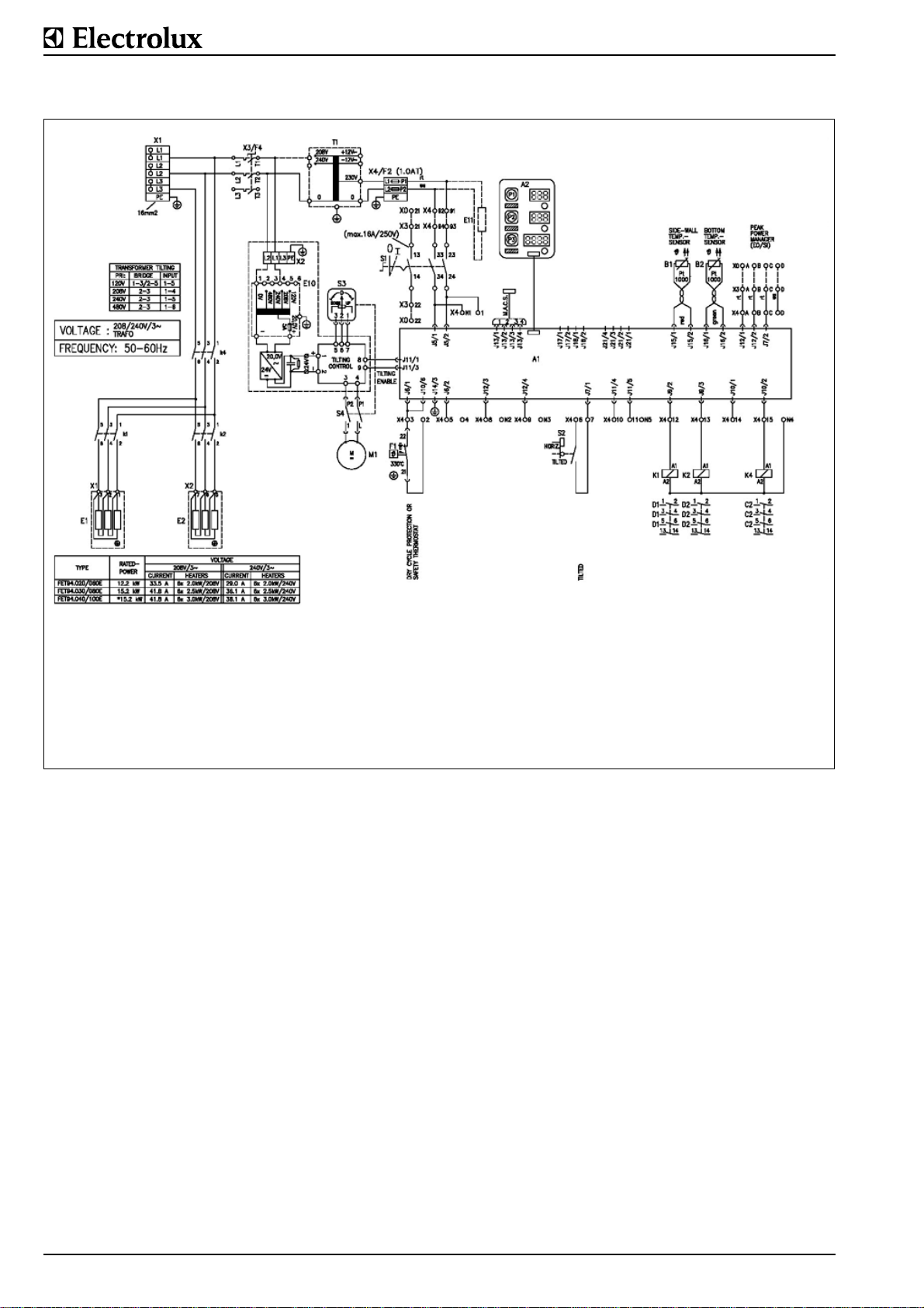
2. ELECTRIC DIAGRAMS
A1 Control print
A2 Operating print
B1 Food temperature sensor
B2 Bottom temperature sensor
E Heating elements
E10 Tilting control
E11 Heating resistor
Fig. 1 Electric diagram, electrically heated frying pan60 LT - 100 LT (15.9 gal - 267.4 gal) 208 V and 240 V
F1 Excess-temperature thermostat
K1.2 Contactors
K4 Safetycontactor
M1 Tilting motor
Q1 Power isolator, optional
S1 Control switch
S2 End switch for horizontal position of
the pan
S1 Tilting switch
X0-.. Terminals
X4 Control fuse
T1 Single- phase transformer (only for
voltage 230V)
EO/SI Connection for energy optimizing
system
The precise specifications of the individual electric components are given in the corresponding parts list. These must be
used in conjunction with the electrical schematic valid for the
appliance.
Page 4 62.9694.03
Page 6

A1 Control print
A2 Operating print
B1 Food temperature sensor
B2 Bottom temperature sensor
E Heating elements
E10 Tilting control
E11 Heating resistor
Fig. 2 Electric diagram, electrically heated frying pan60 LT - 100 LT (15.9 gal - 267.4 gal) 480 V
F1 Excess-temperature thermostat
K1.2 Contactors
K4 Safetycontactor
M1 Tilting motor
Q1 Power isolator, optio nal
S1 Control switch
S2 End switch for horizontal position of
the pan
S1 Tilting switch
X0-.. Terminals
X4 Control fuse
T1 Single-ph ase transformer (only for
EO/SI Connection for energy optimizing
The precise specifications of the individual electric components are given in the corresponding parts list. The se must be
used in conjunction with the electrical schematic valid for the
appliance.
voltage 230V)
system
62.9694.03 Page 5
Page 7
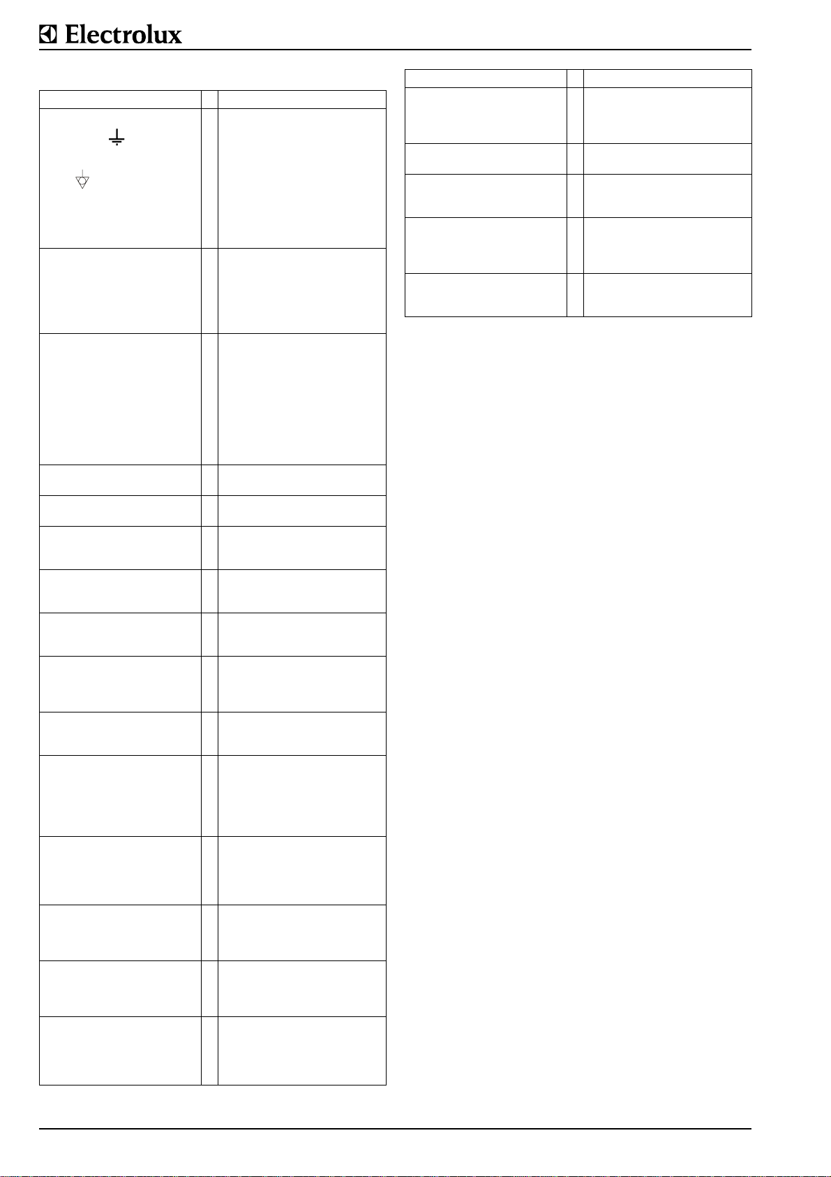
3. MAINTENANCE CHECK LIST
Check Fault B Remedy
Connections for protective
conductors
Connections for equipoten-
tiality
Check that all electric con-
nections and contacts to
terminals, coils, switches
and junctions are tight.
Check contactors and
relays.
The contacts must move
freely without sticking or
jamming. Check all contactors for traces of burning.
Measure the individual
phase currents with a
clamp-on ammeter on the
power supply immediately
before the connection terminals with the appliance
switched on full and compare the currents with the
data on the electrical schematic.
Inspect internal wiring. In case of defect cables
Check condition of all oper-
ating foils.
Optical inspection of the
whole control unit.
Test all operating functions
and check that the control
unit works correctly.
Check switches for easy
movement and correct function.
Compare the digital display
of the bottom temperature
with the actual value measured.
Compare the food temper-
ature display with the actual
value.
Inspect fixation and condition of all temperature sen-
sors (jacket, food,
deaeration, excess temperature) and check electrical
connections.
Inspect condition and function of the safety thermo-
stat.
Test if all heating elements
work well by measuring the
indicated heating-up time or
measure the current.
Check all elements of the
display on the operating
panel with service test 1.
Inspect fixation and condition of all switches (power
isolator, control, tilting, stirrer) and check electrical
connections.
In case of loose contacts
B tighten contacts.
In case of defects or faults B
replace contactor or relay.
Identify defective consumers
(heating systems) by carefully measuring the individual currents. If major
deviations are discovered
B Replace.
B replace cables.
Defective foils
B replace.
S If faults are discovered
B repair faulty units or
exchange parts.
S If problems are encountered
B find reason and repair failure.
If the switch is hard to turn or
makes a noise
B replace.
If the deviation is
B trim the display again.
If the deviation is
B trim the display again.
S If sensors, fixation, electrical
connections are found to be
faulty
B replace the parts concerned.
If sensors, fixation, electrical
connections are found to be
S
faulty
B replace the parts concerned.
If larger differences are noted
B exchange the faulty heating element.
If any element of the display
fails
B exchange the whole operating print.
If defects to any fixation or
electrical connections are
discovered
B replace the parts concerned.
5°F
1°F
Check Fault B Remedy
Check function of acoustic
signals.
Check the lid for correct
shape or damage.
Check the lid hinges for
correct function.
Inspect pipework and screw
connections (pans with
external heating) for tight
sealing.
Check function of mixing
unit for function. Check for
leaks of water connections.
S = Part is relevant for safety
If, during servicing, an increased number of failures is
noted for a part that is relevant for safety, a written report
must be sent to the "Aftersales" office responsible without
delay
Measuring the temperature of the pan base
Precise measurement of the temperature of a pan base using
methods in which contact with the base takes place by touching it with a probe (thermocouple, thermometer, etc.) is very
unreliable and generally leads to deviations in the order of
minus 68°F (20°C) to 104°F (40°C). The use of heat-conducting paste does not result in any substantial improvements.
Correct results can be achieved by means of infrared measurement using a pyrometer (e.g. Raytek's Raynger, series
ST2L). To prevent reflection from the pan base, a heat-resistant, fibre-glass tape (e.g. Scotch Brand tape from 3M) must be
bonded to the area to be measured. A surface area of 2 x 2
inch) 5 x 5 cm is enough for this purpose.
If the sound is offkey or no
sound is heard
B exchange the whole control print.
If irreparably damaged
B replace the lid.
If defective
B disassemble, clean,
grease, adjust the hinge.
In case of leakage
B replace seals or pipes.
If the tap drips or if any pipes
leak
B replace seals.
Page 6 62.9694.03
Page 8

4. ACCESS TO INSIDE
Sheeting of console, support, pan
Remove the connecting rail
(VS)Loosen the front nuts M6
from underneath. Bend the rail
up slightly at the front. Pull the
rail out of the appliance.
Switch panel (F) removal:
Unscrew the two screws at
location (1) underneath the
switch panel and the nuts (MH)
at location (2) on the top, pull
out the switch panel at the tom
and then lift up out of the fixation. The panel is turned up 90°
like a door and hung at the top
on the console.
Cover (A) removal:
If there is a connecting rail
installed to the cover it has to
be removed first. (see 5.3.1.).
Remove the nuts (MU) (two on
a single console, four on a twin
console) at the relevant location (2). Lift the cover at the
front and pull it out of its clip
attachment at the back (3). If a
mixing unit is fitted, this does
not need to be removed from
the cover.
Service panel (V) removal:
Remove the two external nuts
(6) at the front and pull the
panel from its rear attachment
points (5).
Sidewall (S) removal:
To remove this, the switch
panel (F) must be removed
first. Remove the nuts (4) and
(5) inside. The upper internal
wall (W) cannot be disassembled. It must be removed and
refitted together with the pan.
The panels are refitted in the
reverse order to that described
above.
Cover (A). The height of the
cover can be levelled by fitting
more or fewer shims (BE) and
tightening the nuts (MH).
Floor mountingh
Hanging the operating panel
(F) on the console
Removing the pan base
(BD).
Set the pan in the horizontal
position. Remove the screws
(SB) from underneath and
take out the base (BD) from
underneath.
Fitting the base (BD).
Carefully clean any remains
of the old seal from the edge
of the base. Stick a new
sealing strip (DB) on the
edge of the base. Carefully
position the threaded clip
(SM) on the jacket (MK).
Tighten the screws (SB).
Pan jacket. The pan jacket
is not removed during normal
servicing work. Please refer
to § FU1.6 for instructions.
Removing the Front pan
cover (VA):
The front panel of the pan
cover can be removed as follows without removing the
base (BD): remove the front
screws (SB), pull off the
panel underneath the pan,
draw the panel down and out
of the pan flange.
5. FUNCTIONAL COMPONENTS
5.1 FU1. OPERATING FOIL EXCHANGE Removal
Operating foils (FO) are bonded to the sheetmetal surfaces
(cover plates) with self-adhesive coatings. They are removed
with a spatula, a screwdriver or a knife.
Cleaning
The surfaces to which the foil is to be applied
must be clean and dry, i.e., free from dust,
grease, rust, paint, etc. Suitable for cleaning:
toluol or 3M article S-152 stick remover.
Procedure: shake the can thoroughly and
spray evenly on the surface to be cleaned.
(Distance about 6 - 8 inch (15 - 20 cm).) Rub
over with a clean lint-free cloth. If surfaces are
heavily soiled, repeat the process.
Sticking on the foil
Remove the protective backing, taking care
not to touch the adhesive. After positioning
press down well. It is important to apply firm,
even pressure. The ideal working temperature
is approximately 77°F (25°C). Temperatures
below 50°F (10°C) should be avoided since
the adhesive becomes too hard and instantaneous adhesion is reduced. Following application, the foil has a working temperature range
from -40°F (-40°) to +248°F (+120°C) continuous temperature load and 356°F (180°C)
short-time temperature load.
62.9694.03 Page 7
Page 9
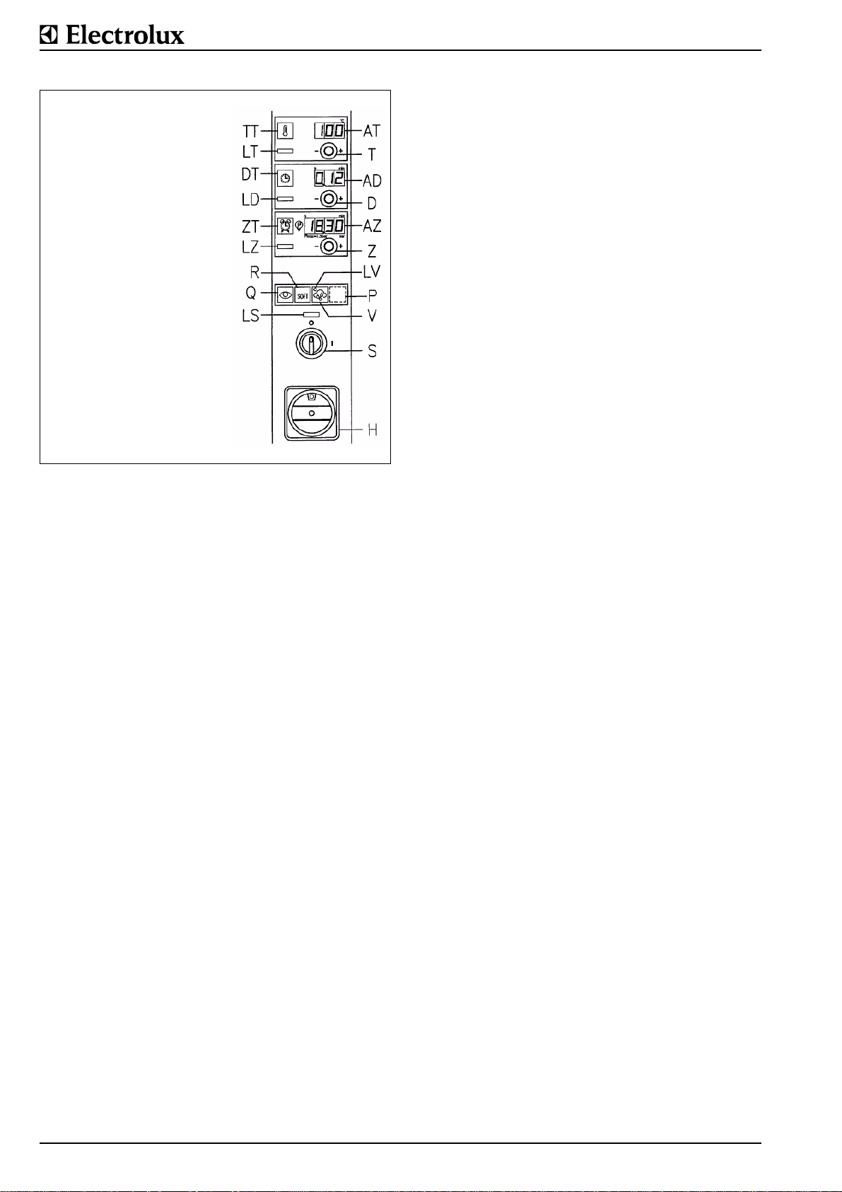
5.2 FU2. UNIVERSAL CONTROL
TT Button, activation of settings
LT Lamp, cooking temperature
DT Button, cooking time
LD Lamp, cooking time expires
ZT Button, starting time
LZ Lamp, starting time
Q Button, acoustic signal
R Button, soft
LS Lamp, temperature
pre-setting
AT Display, cooking tempera-
ture
T Temperature selection knob
AD Display, remaining cooking
time
D Cooking time knob
AZ Displ ay, time
Z Starting time knob
LV
P
V
S Control switch
H Switch on the power isolator
The appliances are equipped with a precise state-of-the-art
electronic microprocessor control system.
• Comfort control with digital preselection of bottom resp.
food temperature and cooking time,
• Process Comfort control with additional digital preselection
of starting time and automatic steam condensation after
pressure cooking for pressure braising pans.
The control system can also be remotely controlled using a
PC. For control-system operation, please refer to the Operating Instructions.
The symbol on the operating foil as well as the function of
the key (V) for steam condensation after pressure cooking
is only present on tilting pressure braising pans.
Temperature setting
Cooking
If the nominal temperature set on the display (AT) is equal or
lower than 230°F (110°C), control takes place via the food sensor fitted to the external side wall of the pan. The appliance is
set to the "Cooking" operating mode. The nominal temperature
is reached during heating up and then kept at this value - but
not exceeded - by electronic control and energy is supplied as
and when required. If pressure cooking is not selected, a maximum setting of no more than 212°F (100°C) is recommended.
Frying
If the nominal temperature set on the display (AT) is higher
than 230°F (110°C), control takes place via the bottom sensor
fitted underneath the pan. The appliance is set to the "Frying"
operating mode. The nominal temperature is reached during
heating up and then kept at this value - but not exceeded - by
electronic control and energy is supplied as and when
required.
When the appliance is switched on (switch S), the contactor
(K4) is also always energized. The two other contactors (K1
and K2) switch the heating on and off simultaneously as
required, i.e. with a mutual delay of approximately 1 second.
Displays
AT (3 di gits) Temperatures (if all 3 digits light up as well as
the point after the third digit, then this means
that 0.5°F must be added on after the point).
Parameter number (PNo.).
Parameter value (if all 3 digits light up as well as
a decimal point, then the numeral must be multi-
plied by 1000. E.g. display = 3.99, value =
3990).
Software version.
AD (3 digits) Cooking time.
AZ (4 digits) Clock time.
Starting time.
Delay time.
5.2.1 PARAMETER PROGRAMMING
General remarks
The same software is used for all appliances which are
equipped with this control system. To ensure that each a ppliance operates as desired, specific parameters must be
entered. The control systems which are installed in the appliances at the factory or are in stock, are equipped with the
microprocessors fitted including the software. The software
contains a default setting (GS) of the parameters (PNo.). The
default setting is selected in such a way that a minimum of
parameters have to be adjusted for the individual setting of the
different appliances. In principle, the corresponding parameters have to be entered for each appliance.
Software version
The microprocessor (MP) bears an adhesive label stating the
software version and the date. Any change in the software
usually also involves a change in the parameters. Please
always ensure that the version of the parameter list used
matches the software version. The following general rule
applies: if the software version has a different number, the
parameter list with the same version must also be used. If the
software version has a different additional letter in the version
number (e.g. version 2.51A, version 2.51B, etc.), the parameter list does not change. Only the number of the version wi thout the additional letter is important for the parameter list.
Microprocessor (MP)
2 IC insertion sockets are located on the control print. The
large insertion socket for 64 pins accepts the microprocessor.
The software program is located in the ROM (Read Only Memory) of the microprocessor chip. An OTP version (One Time
Programmable) microprocessor is used. This version can only
be written to once and cannot be erased. This mean s that any
program change also means the use of a ne w chip. The old
chip can no longer be used.
EEPROM (EP)
2 IC insertion sockets are located on the control print. The
small insertion socket for 8 pins is for the EEPROM (Electrically Erasable Programmable Read Only Memory). The
parameters are stored in this IC. Once stored, the parameters
remain in this IC even when disconnected from the power supply until they are changed by reprogramming or erased.
Before the parameters are changed for the first time to suit an
appliance, the values for the default setting must be loaded
into the EEPROM. The parameters can be entered in 2 different ways:
Manual input (the more frequent case) and PC input.
5.2.2 MANUAL PARAMETER INPUT
Default setting (GS) of the parameters
The default setting of the parameters is the same for all appliances which are equipped with this control system. Dependent
on the type of appliance, more or fewer parameters are
required with values that differ from each other to some
degree.
3 of the 4 buttons on the membrane keyboard (Q, R, V a nd P)
are used for the programming of parameters. The buttons are
located in the bottom row on the operating panel. Buttons V
and P are located under the membrane and are not visibly
marked.
Page 8 62.9694.03
Page 10
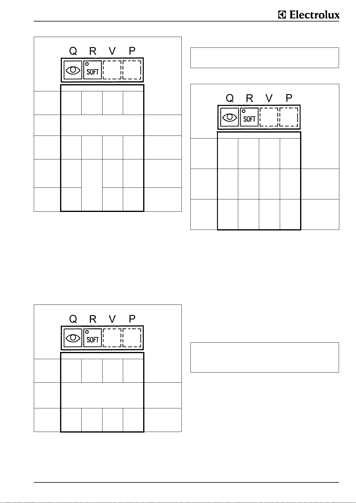
)
Ï
Ð
Starting position: supply switched off (switch S at 0)
1st
combination
Press and hold
buttons
2nd
combination
Press buttons
3rd
combination
Press buttons
4th
hold
button R
* *
Supply to be switched on (turn switch S to I) Press buttons continu-
* *
*
*
⇓
⇓
*
Waiting time between
the different combinations is 3 seconds
maximum
ously until the 2nd
beep, then press the
2nd combination
Press buttons continuously until the 2nd
beep, then press the
3rd combination
Press buttons continuously until the 2nd
beep
Hold button R pressed
until the 2nd beep,
then release.
(*)
(*) Display (AT): After "def" is displayed for approx. 2 seconds,
the actual value of the current food temperature will appear.
Display (AZ): Clock time appears (only with process com-
fort control).
The control system program now contains all the default settings for the software version of the microprocessor installed.
Important
If the default setting (GS) of the parameters of an appliance
which was already in operation is programmed for new, all
parameters which registrate running times are set to zero.
Parameter-setting (X) specific to each appliance
In order to change the numbers (PNo.) and the content (X) of
the parameters, the same buttons are used as those for entering the default setting..)
Starting position: supply switched off (switch S at 0)
1st
combination
Press and hold
buttons
2nd
Press button
* *
Supply to be switched on (turn switch S to I) Press buttons continu-
Waiting time between
the different combinations is 3 seconds
maximum
ously until the 2nd
beep, then press 2nd
combination (for the
first time only 1 beep)
Hold button R pressed
until the 2nd beep,
then release.
*
Display (AT): Parameter PNo. . . 1 appears
Display (AZ): None
The parameter numbers (PNo.) and the values (X) which devi-
ate from the standard setting can now be entered alternately
on the display (AT).
As the same display is used to show the numbers (PNo.) and
the content (X) of the parameters, the following difference is
made between the two figures:
Kind of display (AT): Meaning of display:
with 3 decimal points (e.g. 1.0.3.) Number of parameter PNo
without decimal points (e.g. 126) Content (X) of parameter (e.g. temperature)
Changing the parameter number (PNo.) and content (X))
Starting position: supply switched off (switch S at 0)
1st
Press button
2nd
Press button
3rd
Press button
*
*
*
Changing
(AT) from:
parameter number
(PNo.) to
parameter content (X)
or vice versa
Increasing the display
entered under 1.
parameter number
(PNo.)
or parameter content
(X)
Reducing the display
(AT):
parameter number
(PNo.)
or parameter content
(X)
the display
Rate of change of the displays
Increases (button P) or reductions (button Q) can be done at
three different speeds:
• Press the button brieflychanges in single steps
• Press the button longer
• at least 1 second the display changes slowly
• press for at least 5 seconds the display changes fast
End of parameter programming
If the content (X) of a parameter (PNo.) is changed, the
changed value is stored when the display (AT) is changed
from parameter content to parameter number using the button
R. The following applies for the last parameter content
changed or if only a parameter content has been changed.
Parameter programming can be finished in 2 ways dependent
on whether the changed value is to be stored or not.:
Finishing: Procedure:
Changed value to be
Changed value
not
stored
to be
stored
Display (AT) shows the
Switch off control switch (S)
Display (AT) shows the
Switch off control switch (S)
parameter number
parameter value (X)
5.2.3 PROGRAMMING SPECIFIC APPLIANCE AND
USER DATA
Appliance-specific parameters are only set on the basis of the
type of appliance. User-specific parameters are dependent on
user order, user requirements, siting terms an d are only appliance-dependent to a certain degree.
The parameters are programmed at the factory to the default
setting (GS) if no specific information is given.
New appliance installation
In the case of new appliances, the control system is programmed at the factory to the appliance-specific setting.
When the appliance is installed at its intended site, the fitter in
charge of installation must set or check the following parameters on the control system. The parameter values are different
for each software version.
62.9694.03 Page 9
Page 11
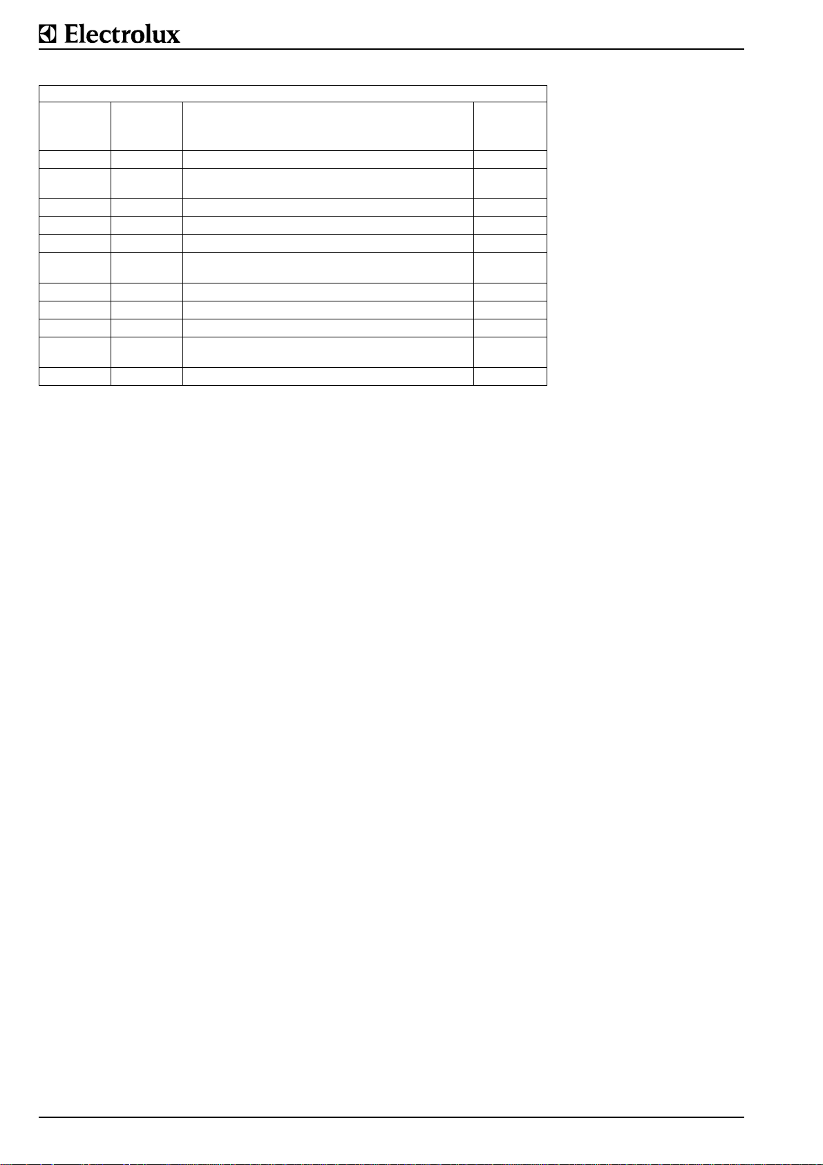
PARAMETER SETTINGS
SOFTWARE VERSION BPTH 5.06
PNr.
Parameter
number
GS
Default
setting
Designition
1 0 Temperature display 1
4 0 Energy optimization system EO
6 Heating with tilting 1
19 1 Power settings and boiling temperature 0
29 1 Deaeration sensor of the jacket 0
32 0 HACCP function
49 0 Appliance code 3
50 1 Appliance type 2
54 4 Quantity of switching steps 2
83 50
Input of height above sea level of the installation site
in 10 m (500 m above sea level. = 50).
157 70 Maximum board temperature 80
Tilting
fryiling pan,
electric
without: 0
with: 1
without: 0
with: 1
X
Page 10 62.9694.03
Page 12
5.2.4 TRIMMING OF TEMPERATURE MEASURING
Measurement accuracy of temperature sensors
In general, the measuring accuracy of the temperature sensors is enough for them not to have to be trimmed. Trimming
the temperature sensors can be done via parameter PNo.
1.0.0. for the food- or pan bottom sensor and via parameter
PNo. 1.0.1. for the jacket- or side sensor. Trimming consists of
entering a certain correction temperature (Offset temperature).
Measuring errors inherent in the system
Every pan has at least one food sensor. Dependent on the
heating system, there is also a jacket sensor. The jacket and
deaeration sensor are not trimmed and corrected. If there is a
temperature difference between the measuring location
(where the sensor is located) and the food, measurement of
the food temperature must be trimmed. This trimming is done
through software with the help of parameters. 2 measuring
points per sensor are provided for trimming. Trimming can be
done at any test temperatures. As correction is a linear function, the temperature difference to be corrected can be converted on a linear basis to the corresponding fixed
temperatures on the X-axis (122°F (50°C) resp. 212°F (100
°C)).
Trimming procedure for the food sensor
• Ascertain the magnitude of ΔT and direction ± of the temperature deviation between the temperature display (AT)
and the food, measured directly with a thermometer in the
cooking space at any temperature. In order to minimize the
error, this measuring temperature should be as high as
possible.
• Convert the deviation measured ΔT to the food temperature 212°F (100 °C) or 122°F (50°C). These two values are
to be used as corrections for the parameters PNo. 1.0.8.
and 1.0.9.
• If the actual food temperature is higher than the temperature shown on the display (AT), the Y-values (PNo. 1.0.8.
and PNo. 1.0.9.) will have to be lowered accordingly.
• If the actual bottom temperature is lower than the temperature shown on the display (AT), the Y-values (PNo. 1.0.8.
and PNo. 1.0.9.) will have to be raised accordingly.
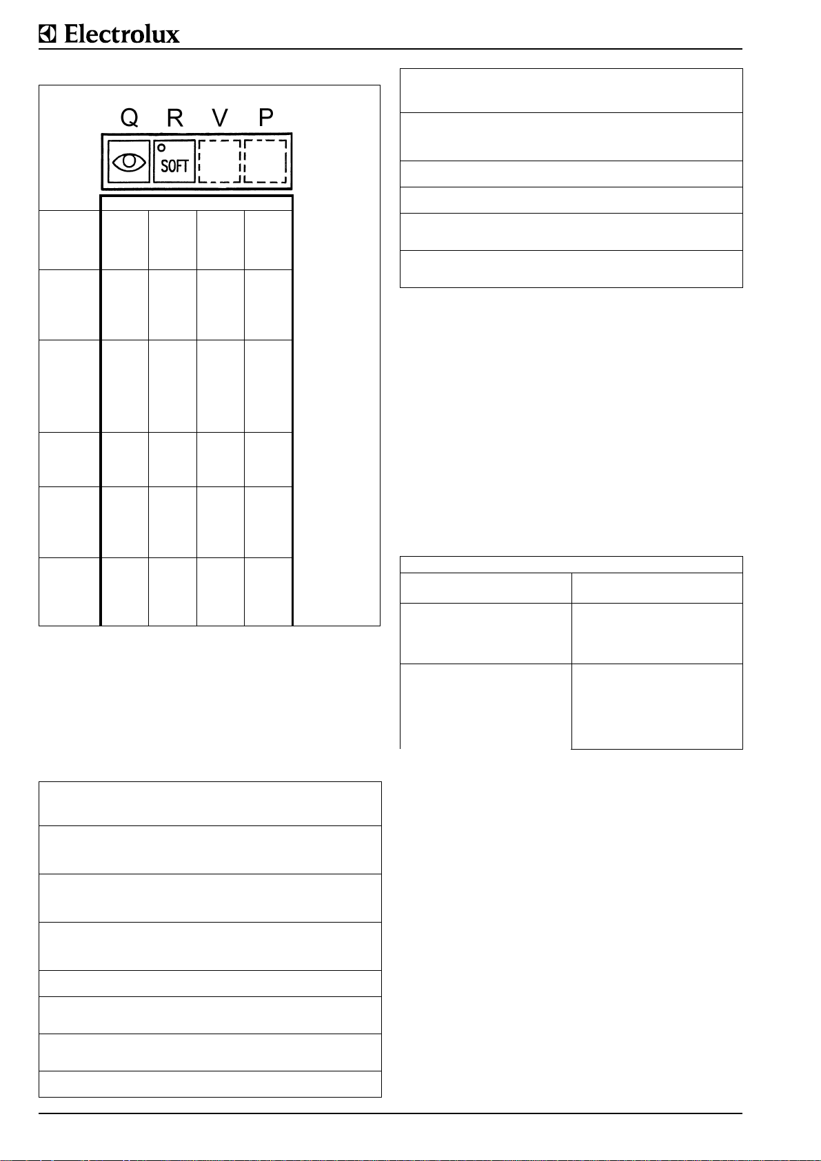
The buttons are located on the bottom row of the operating
panel. The buttons have to be held down for the button combination for the activation of the test displays and the reset. In
order to avoid incorrect functions, always press the Q button
down first before pressing the other buttons.
Example:
Measured bottom temperature 356°F (180°C)
Display (AT) on control panel 392°F (200°C)
Difference -4°F (-20°C)
Translation to bottom
temperature of 212°F (100°C)
+20x(100:180) = +11°C = 51.8°F
Translation to bottom
temperature of 122°F (50°C)
+20x(50:180) = +5.5°C = 41.9°F
Correction for PNo. 1.0.4. = 50 + 5.5 = 55.5°C = 131.9°F
Correction for PNo. 1.0.5. = 100 + 11 = 111°C = 231.8°F
Sign:
If the food temperature measured is lower than the one displayed, the correction values are increased (plus sign). If
the food temperature measured is higher than the one displayed, the correction values are reduced (minus sign).
5.2.5 TEST FUNCTIONS FOR SERVICE APPLICATION
For servicing purposes, various values and operating states of
the control system can be shown on the existing displays with
the help of buttons on the operating panel. The buttons are
also used to reset the jacket refilling display. The cooking process can be switched on or off. All 4 buttons (Q, R, V and P) on
the membrane keyboard are used for service test displays.
62.9694.03 Page 11
Page 13
1st test,
pressbuttons
and hold
2nd test,
press buttons
and hold
3rd test;
press buttons
and hold
4th test,
press buttons
and hold
5th test,
pressbuttons
and hold
Starting position: supply switched off (switch S at I
* * *
* * *
* *
* *
* *
check of
First time:
; the figure 8 is
lamps
shown on all displays,
also all points are displayed
Second time: on display (AT) the
ature
control print
display (AZ) the
time
The display (AT) provides information on
the current
of the heating system
1. electric or gas
ON = switched on,
OFF = switched off
Display (AT) = temperature in °F of food
sensor J15.Display
(AZ) = clock time
Display (AT) =
perature in °F of bottom sensor
Display (AZ) =
time
in °F of the
are shown
condition
:
J16.
temper-
and on
clock
tem-
clock
Display/
failure
code
E10 Response of excess temperature
E21 HACCP Master Personal Computer
E22 HACCP Interface COP485.1 is not
E23 HACCP configuration; EEPROM
E24 HACCP configuration; EEPROM
thermostat; too high temperature of
the bottom
is not connected.
connected.
COP485.1 (memory chip) has found
a reeding fault.
COP485.1 (memory chip) has found
a spelling fault.
Problem Action
Reset the error message and alarm with
button (Q); find cause of too high temperature of the bottom; reset thermostat
(F1) by pressing the red button
Discharge fault display and signal by
pressing button (Q).
Discharge fault display and signal by
pressing button (Q).
Discharge fault display and signal by
pressing button (Q) and repair fault.
Discharge fault display and signal by
pressing button (Q) and repair fault.
FAULTY ERROR MESSAGE
If a faulty error message appears, that is to say, a message
that is inappropriate for the appliance, the appliance's parameters are incorrectly set. This situation can be remedied by correcting the parameters for the appliance in question.
MULTIPLE FAULTS
Two faults may be reported at once, e.g. E7 and E10. The displays follow one another. If, for example, fault display E7 is
reset with button Q, E10 appears on the display (AT). The
appliance will only function perfectly again when the latter has
been remedied and reset.
PROBLEMS WITHOUT DISPLAY
Finding the cause of the fault is dependent on the technicia n's
skill.
6th test,
press buttons
and hold
*
*
*
Display (AT) = number
software version
of
(e.g. 2.62)
Display (AZ) =
time
clock
5.2.6 TROUBLESHOOTING DISPLAY
A fault in the appliance is registered by the electronic control
system and, dependent on the type of fault, is shown on the
display (AT) by the letters E (error) or A (alarm) combined
with a one- or two-digit number. At the same time as the fault
occurs, an intermittent warning tone will sound, the energy
supply is interrupted and the lamp is switched off. Press button
Q to acknowledge the error message (warning tones).
Display/
failure
code
E1 Defective food temperature sensor
E2 Defective jacket temperature sensor
E4 Defective steam condensation sen-
E5 Defective control print temperature
E6 Temperature of food sensor J15 is
E7 Temperature of jacket sensor J16 is
E9 Defective analogue/digital trans-
(J15); appliance switches off
(J16); appliance switches off
sor
sensor
too high
too high
former
Problem Action
Reset the error message and alarm with
button (Q); repair cause of problem
(loose connector, broken sensor, short
circuit)
Reset the error message and alarm with
button (Q); repair cause of problem
(loose connector, broken sensor, short
circuit)
Reset the error message and alarm with
button (Q); repair cause of problem
(loose connector, broken sensor, short
circuit)
Reset the error message and alarm with
button (Q); replace control print
Reset the error message and alarm with
button (Q); repair cause of problem
(defective contactor)
Reset the error message and alarm with
button (Q); repair cause of problem
(defective contactor)
Reset the error message and alarm with
button (Q); replace control print
Problem Reasons
Displays do not light up when
the appliance is switched on
Only the lamp (LS) lights up
when the control switch (S) is
switched on. Other functions
cannot be activated.
The operating displays go
crazy
Control fuse (X4) is faulty
- Water on the control print.
Blow it out and dry the print.
- Microprocessor is not programmed
- Water on the control- and/or
operating print
- The flat cable between the
control- and operating print
is faulty or there is a poor
connection somewhere.
5.2.7 OPERATING PRINT (UP)
If a fault is identified, no repairs can be made to the print. It is
replaced as a complete unit.
Removal
Pull off the operating knobs (BK) on the front of the switch
panel. Then remove the control print (see below). Remove the
long spacing sleeves (HP1). Remove the 6 nuts (MP2) and
washers from the steel panel (ST). Remove the steel panel
and the short spacing sleeves (HP2). Remove the operating
print.
Installation
Proceed in the reverse order to removal. Plug the flat cable
(FL) connector firmly into the print. Make sure that the print is
centered in relation to the windows in the switch panel and the
nuts (MPx) are not tightened excessively to avoid damage to
the print. Replace the operating knobs firmly on the front panel
to ensure that the seals are in place.
When replacing the operating circu it board the bridge JP1 the
position of the bridge JP1 must be checked resp. corrected.
A Bridge JP1 in the upper position
clock time is activated and will be stored
Page 12 62.9694.03
Page 14
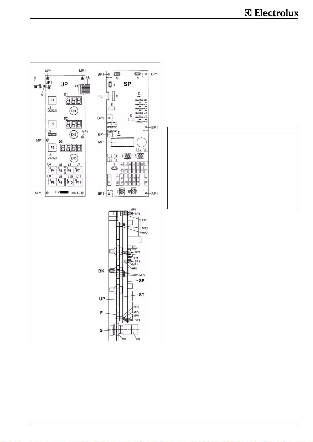
B Bridge JP1 in the lower position
clock time will be not stored, the batterie will not get
unloaded. Condition of the print when getting as spare part
(position of the bridge JP1 for prints on stock).
Removal
Take off the switch panel (F) as described in § 5. Unplug all
electrical connectors from the print. Unplug the flat cable (FL)
connector and take it out of the guide, take off the 6 nuts
(MP1) and washers. Take the print off the steel panel (ST) that
is located between the control print and the operating print and
maintains a gap.
Installation
Place the long spacing sleeves (HP1) on the bolts (BP1) on
the steel panel (ST), position the print on the bolts and carefully tighten the nuts with their washers.
Reprogramming
The general test parameters are set in a new control pcb.
These settings do not correspond to any specific type of appliance. After installing a new control pcb, the basic parameter
values must be programmed in first followed by the parameters that are specific to the appliance (given in the parameter
list).
Control print faults
Reason: Total failure
Exchange: Entire control print Microprocessor (MP) and EEP-
Action: - First request the parameter values of
Water damage
Changeover to a new software version
all sensors and note them down
- Enter the default setting (GS) of the
parameters
- Enter the correction settings for the
software version used
- Enter the appliance-specific setting of
certain parameters
- Enter the user-specific settings
- Enter the sensor corrections noted
above resp. new trimming of the temperature measurement.
Damage to the control print, but
not to the ICs
ROM (EP) on the control print
No settings required
BK operating knobs
HP spacing sleeves
MP nuts and washers
ST steel panel
FL flat cable
JP1 bridge
Fig. 3 Operating print
5.2.8 CONTROL PRINT (SP)
If a fault is identified, no repairs can be made to the print. It is
replaced as a complete unit.
If a control print is replaced, it must be reprogrammed dependent on the type of appliance and user-specific data (see section Programming the control system). The number of the
software version is marked on the microprocesso r.
Handling electronic prints
Electrostatic discharges (ESD) on circuit boards can cause
damage. Even voltages that are imperceptible to human
beings can partially or totally destroy components. Partial
destruction is frequently not noticeable at once and can lead to
early failure. The chain of protection from ESD must not be
interrupted, i.e. the following points must be observed where
electronic components are concerned:
• Transport should only take place in conductive boxes or
antistatic packaging to the place where the prints are to be
fitted.
• Do not reload the prints in non-conductive containers.
• Work on disassembled switch panels (changing prints or
ICs) must be carried out on surfaces of electrically conductive rubber. Servicemen carrying out work of this type must
wear ESD armbands which are connected to the ground
connection on the appliance.
• Do not touch the conductors when handling a print. Always
hold them between your finger and thumb.
• ICs (microprocessor, EEPROM) may only be placed and
stored on conductive foam or in specially designed containers.
• Never hold an IC with your bare hands - only do this when
you are wearing a grounded armband.
The same arrangements and measures also apply to faulty
prints that are returned for repair (warranty claims).
5.2.9 CONTROL SWITCH (S)
Removal
Set the control switch to Position 0. Remove the switch panel
(F) in accordance with § 5. Disconnect the electrical cables
from the contact emitter (KG). Twist the contact emitter counterclockwise slightly by hand until it separates from the front
switch part. Unscrew the nuts (MS) and take out the handle
part at the front. (See picture Operating Print UP).
62.9694.03 Page 13
Page 15
Installation
Proceed as described under "Removal" but in the reverse
order. Make sure that the seal between the sw itch panel (F)
and the handle part is correctly installed and undamaged. The
cam on the handle part must also engage with the aperture in
the switch panel.
5.2.10 SAFETY THERMOSTAT (F1)
The purpose of the safety thermostat is to protect the electric
heating from overheating. The thermostat switch is in the base
plate of the pan. If the thermostat responds, the red button
(RF1) will jump out and the heating will cut out. After the cause
of this response has been remedied, the red button is pressed
in again and the appliance is then ready for use again.
Problem Reasons
The safety thermostat (F1) has responded Possible causes:
If the capillary tube of the safety thermostat
is defective, the function of the boiling pan
is blocked.
If the ambient temperature of the thermostat decreases under -10°C (transport or
stocking in winter) the thermostat switches
off and the function of the boiling pan is
blocked.
- Control fault
- Capillary tube fitted to (F1) is broken
- Food temperature sensor (B1) or the bottom
temperature sensor (B2) is not fitted
correctly (no contact)
- Contactor is jammed
- Attachment and local position of the sensor
(F1) has changed.Identify and remedy the
cause or replace the relevant part..
Replace the thermostat.
Reset the thermostat at room temperature.
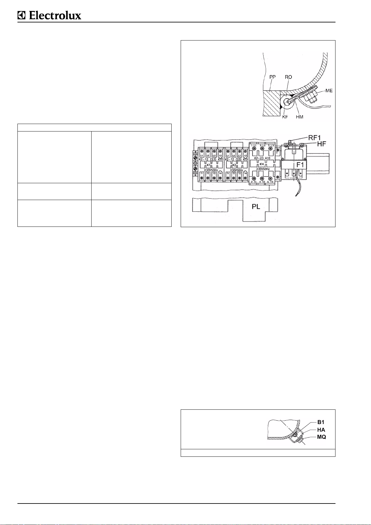
The thermostat switch (F1) is located in the right console on a
plate besides the terminals. It switches the heating off when a
temperature of 330 +0/-17°C is attained.
Resetting:
By removing the cover (A) of the right console according to
§1.5 the red button (RF1) can be actuated.
Removal:
The cover (A) of the right-hand console must be removed.
Remove a nut from the sheet (PL), lift the sheet with all electrical parts up and hang the sheet on the console. Disconnect
the electrical connections from the thermostat. Remove the
two attachment screws (HF). Set the pan in the fully tilted position. Remove the bottom of the pan cladding as described in §
1.5 by releasing the screws (SB). In order to remove the capillary tube sensor (KF), it is necessary to take off the insulation
panel (IB), the pan Insulation (IA) as well as the radiation panel
(IR) This is done as described under the section "Electric heating". The capillary tube sensor is located on the rear of the pan
bottom plate (PP) in a tube (RO) and is fixed by a retaining clip
(HM). The sensor can be removed by releasing the nut (ME).
Tie a strong cord to the sensor. Pull the capillary tube sensor
out of the appliance through the pan pivot. Untie the cord from
the sensor and leave it in the appliance.
Installation:
Tie the cord tightly to the new sensor and pull it back through
the appliance. Proceed as described under "Removal" but in
the reverse order.
F1 thermostat switch
RO tube
ME nut
KF capillary tube sensor
HF attachment screws
PL sheet
Fig. 4 Safety thermostat
5.2.11 FOOD SENSOR (B1)
The food sensor (B1) is located on the front wall of the pan
roughly in the middle.
Test
Disconnect the sensor cable from the control print. Measure
the resistance with an ohmmeter at the ends of the cables.
They should show a resistance of 1097Ω at 77°F (25°C).
Removal
Remove the front wall of the pan cladding (see § 1.5). Release
the nut (MQ) and withdraw the sensor (B1) from the attachment owner (HA). Dismantle the switch panel (F) on the righthand console as described in § 1.5. Disconnect the sensor
cable at the J15 push-on connections on the control print (SP).
Attach a strong cord to the end of the cable. Pull the cable out
of the appliance through the pan pivot. Take the cord off the
cable and leave it in the appliance.
Installation:
Attach the cord well to the end of the cable on the new sensor
and pull the cable through the appliance again. Proceed as
described under "Removal" but in the reverse order. Make
sure that the flat side of the sensor is pressed well against the
pan with heat conducting paste (Rüeger/Crissier RTP/II).
Following replacement, the sensor must be retrimmed as
described under "Trimming".
B1 sensor
HA attachment
MQ nut
Fig. 5 Foot sensor
BOTTOM SENSOR (B2)
The bottom sensor is inserted roughly in the middle of the pan
bottom. The active part of the sensor protrudes into the pan
bottom. Bottom temperature is acquired by using test 5 (see
"Test functions").
Page 14 62.9694.03
Page 16
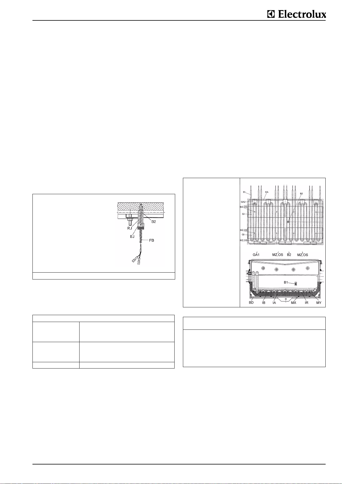
Test:
Disconnect the sensor cable from the control print. Measure
the resistance with an ohmmeter at the ends of the cables.
They should show a resistance of 1097Ω at 77°F (25°C.
Removal:
Remove the bottom of the pan cladding (see § 1.5). It is not
necessary to remove the pan insulation to take out the sensor.
The sensor (B2) is attached by a sleeve (BJ) with a bayonet fitting to the protection tube (RJ). Remove by pressing the
sleeve (BJ) and twisting it counter clockwise. Remove the
switch panel (F) on the right-hand console as described in §
1.5. Disconnect the sensor cable at the J16 push-on connections on the control print (SP). Attach a strong cord to the end
of the cable. Pull the cable out of the appliance through the
pan pivot. Take the cord off the cable and leave it in the appl iance. The protection tube (RJ) cannot be removed.
Installation:
Attach the cord well to the end of the ca ble on the new sen sor
and pull the cable through the appliance again. Proceed as
described under "Removal" but in the reverse order. Make
sure that the tip of the sensor is pressed well against the pan
with heat conducting paste (Rüeger/Crissier RTP/II). The po sition of the sleeve (BJ) can be altered by twisting the spring
(FB) and should be positioned with a gap of approximately 70
mm from the end of the sensor to allow the sensor to be
pressed against the measuring point with enough force.
Following replacement, the sensor must be retrimmed as
described under "Trimming".
Removal
In the case of design A of the cooling water system first
remove the water pipes (LD1) and (LD2) from the left pivot by
removing the screws (HD) and the two retaining disks (HT)
and turn out the pipes (see § "FU2.7. Cooling Water System").
Turn the pan completely, i.e. by rotating it 180°. This is done
by disconnecting the tilting drive and propping (see § FU1.3).
Take off the bottom of the pan cladding (BD) as described in §
1.5. Unscrew the nuts (MX) with which the panel (IB) that holds
the insulation (IA) is attached. Remove the panel (IB) and the
insulation (IA). Remove the nuts (MY) and remove the radiation panel (IR). Proceed as follows to replace a heating element (EI) or (EA): Disconnect the electrical connections,
remove the clips for the inner heating element (GI) or for the
outer heating element (GA1) and (GA2) by taking off the relevant nuts (MZ) and spring washers (OS), then remove the
heating element from the bottom of the pan.
Installation
Proceed as described under "Removal" but in the reverse
order. Please observe the following points during assembly:
• Clean the threads of the heating element fixing screws with
a wire brush and lubricate with Molykote paste P37 (Dow
Corning)
• Fully tighten the nuts (MY) with their lock washers (OS)
and then slacken by ¾ of a turn (relieve).
B2 sensor
BJ sleeve
FB spring
RJ protection tube
Fig. 6 Bottom sensor
5.2.12 ELECTRIC HEATING (EI, EA)
The electric heating system (5 items (EI) on all types inside
and 1 item (EA) as a loop around the perimeter) are fitted
underneath the pan bottom and transmit the heat by radiation
and conduction.
Problem Reasons
Pan refuses to heat up - Safety thermostat in the jacket has responded. Fault is dis-
Pan heats up too slowly - Heating is faulty
Contactor hums or chatters - Contactor is dirty or faulty (replace)
played as error message E10.
- End switch (ES) is faulty, no longer in the correct position,
no contact; screw (SZ) is no longer in the correct position.
- Fuse burnt out
- Contactor is faulty
- Wiring is loose (e.g. one phase at connection)
If heating elements fail, the entire period that the appliance has
been on can be obtained from the control system by invoking
parameter PNo. 1.6.3 so that conclusions on early failure or
long-term faults can be drawn. After replacing the heating,
reset the parameter value of PNo. 1.6.3 to 0.
Testing
Measurement of the electrical resistances of the individual
heating loops (measured at both plugs of a heating loop) with
an ohmmeter with the appliance completely switched off and
comparisons with the nominal values (please refer to the table
below for details). Access to all the heating connections is
gained by removing the front wall panel of the pan as
described in § 1.5.
Fig. 7 Electric heating
Tilting frying
pans
Wattage per heating
element W
Nominal resistance (cold)
Voltage 208 V 21.6 17.3 14.4
Voltage 240 V 28.8 23.0 15.2
Voltage 480 V 39.2 31.4 26.1
60 LT
(15.9 gal)
2000 2500 3000
80 LT
(21.1 gal)
Ω
100 LT
(26.4 gal)
Deviations in output or resistance from the manufacturing tolerance can amount to +5/-10 %.
5.2.13 END SWITCH (ES)
The end switch is located in the right-hand console and serves
to switch off the heating when the pan is tilted from its horizontal position. On the tilting pivot, there is a protruding screw
which operates the end switch.
Setting
Insert the screw (SZ) into the pivot (KA) and secure it with a
lock nut. Fix the end switch (ES) securely to the holder (EH)
with the two screws (SX). Set the pan horizontal. Slide the
holder (EH) vertically until the lever (EB) trips the switch. The
switching action is clearly audible. Tighten the two screws (SE)
firmly in this position. The end switch must switch off when a
tilting angle of 10 degrees is reached.
62.9694.03 Page 15
Page 17
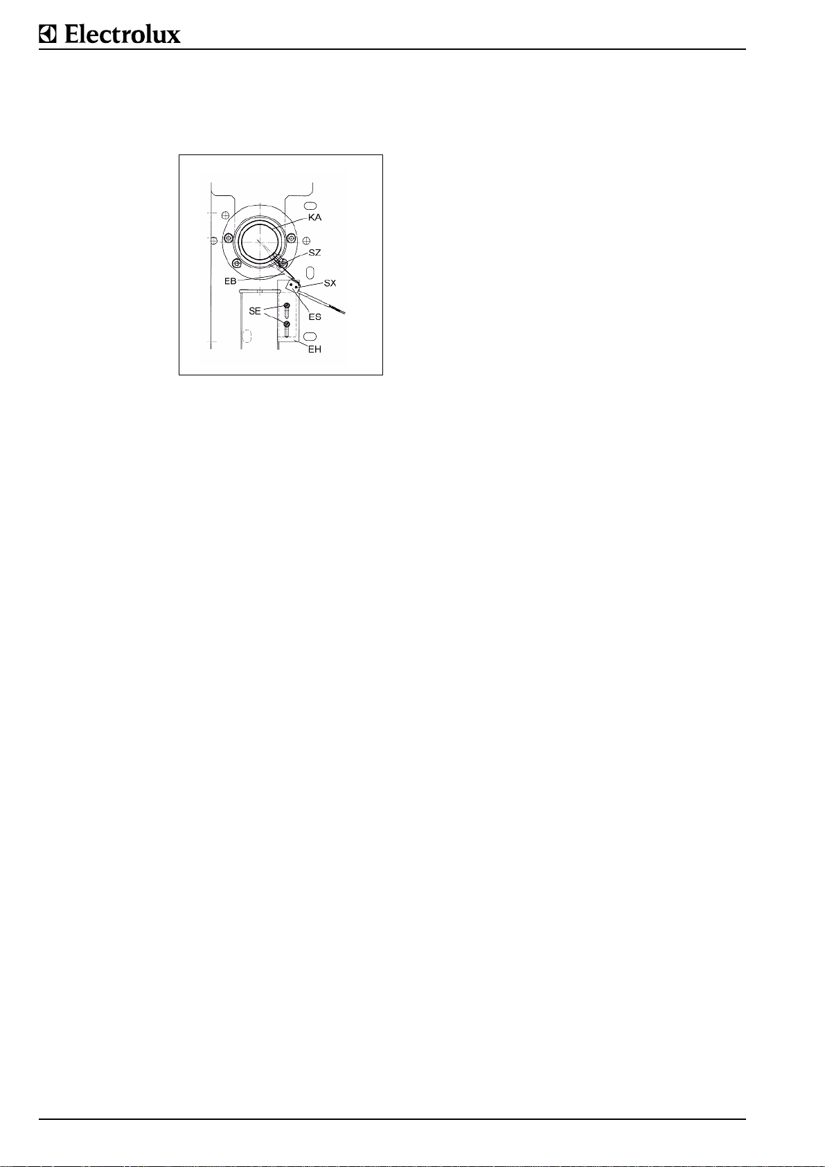
Removal/Installation
Remove the screws (ES). Resetting is necessary after replacing the switch.
Fig. 8 Electric heating,
detail
5.2.14 TERMINALS
Removal and installation
The terminal rail is located in the right-hand console and can
be accessed from above after removing the cover (A) as
described in § 4. Normal terminals are only clipped into the rail
and can be released with the help of a screwdriver. The earth
terminal is also attached by a central screw which has to be
released during removal.
5.2.18 POWER ISOLATOR (H)
Only optionally available in the lower part of the switch panel.
Removal
Remove the switch panel (F) as described in § 4. Detach the
electrical connections from the switch. Release the screw in
the center of the knob and pull off the knob. Take off the panel
cover with the setting displays. Remove the 4 screws, nuts and
washers with which the switch is attached to the panel. The
terminal plate and the rear part of the switch can now be
removed from the switch panel.
Installation
Proceed as described under "Removal" but in the reverse
order. Ensure that the seal on the switch shaft is undamaged;
the V-shaped notch on the switch shaft must be on the right;
the terminal plate must be aligned precisely in the switch
panel; fit the panel cover so that 0 is at the top and I is on the
right; fit the handle so that the window is at the top to reveal
the 0.
5.2.15 CONTROL FUSE (X4)
Removal and installation
The fuse (either one or two may be fitted) for the pan control
print is located in the right-hand console on the terminal
assembly. Take off the cover (A) as described in § 4. Open the
cover of the fuse clip by flipping it open on one side. Ta ke out
the fuse sideways or insert a new one. The fuse is located
loosely in the holder. Reclose the terminal cover.
5.2.16 CONTACTORS (K)
Removal
Take off the cover (A) as described in § 4. The terminal
assembly and the contactors are mounted on a common support plate. Unscrew the nuts with which the support plate is
attached to the frame. Pull the support plate upwards out of
the console and insert the lower part of the plate into the cutout
in the console frame. The support plate then remains in an elevated position above the console which allows easy access to
the contactors from the side. Detach the cable connections
from the contactor. Release from the snap fitting in the middle
of the foot using a screwdriver and take off at an angle on one
side.
Installation
The contactor is simply clipped onto the rail with a snap fitting.
Cable connections. Continue as described under "Removal"
but in the reverse order.
5.2.17 HEATING RESISTOR (E11)
This heating is used for protecting the control system against
condensing water. It is alwaya switched on when the appliance is connected to the supply.
Removal and installation
The heating is mounted to the console behind the control
panel. Remove the control panel (F) and the cover (A) as
described in § 4. Detach the electrical connections. Pull the
heating out of the two clamps.
Page 16 62.9694.03
Page 18
5.3 FU1.3. MOTOR TILTING
All parts of the tilting mechanism (control system, tilting motor,
tilting switch) are located in the left-hand console.
Problem Reasons
Tilting drive refuses to operate - Control fuse is faulty
- Water in the controls (general)
- Fault on the print
- Potentiometer on the switch is disconnected or faulty
- Tilting motor (gearbox, shaft) is faulty
- Tilting control is not being released by the
pan controls. The parameter PNo. .1.6.
programmed into the pan controls must be
correctly set at 1.
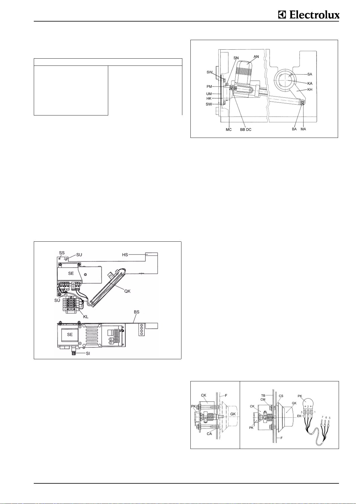
5.3.1 CONTROL SYSTEM (KS)
This consists of the power supply unit (SE) and the control
print (QK). The control board (QK) is also new and has 10 contacts (no. 10 stays emty). All parts are compactly mounted on
a sheetmetal support.
Removal:
Remove the cover (A), the front panel (F) and, if possible, the
sidewall (S) as described in § 1.5. Remove the guard which is
positioned above the controls to keep water off them by undoing the screw (SS) and withdrawing the plate on the right from
the mounting. Disconnect the electrical leads. Take away the
two screws (SU). Pull the entire sheetmetal support (BS) out of
the right-hand mounting (HS) and take the controls out from
the top.
Installation:
Proceed as described under "Removal" but in the reverse
order.
Fig. 10 Motor tilting removal
Remove the screw (SN) and its washer. Remove the plate
(PM). Raise the tilting motor at the back and take it out of the
console. Also remove the bolt (BB) and the spacer (DC) by
removing the nuts (MC). Dismantle the tilting handle (KH) from
the tilting shaft (KA) by undoing the screw (SA) and pulling the
handle from the shaft.
Installation
Proceed as described under "Removal" but in the reverse
order.
Adjustment
it is only possible to adjust the horizontal position of the pan
precisely by varying the packing (UM).
Procedure
Remove the cover (A) as described in § 5. The entire drive
must be fully assembled. Set the pan in the horizontal position.
Release the two screws (SW). The moment of force on the pan
will draw the mounting (HK) away from its attachment point.
This allows the thickness of the packet of packing (UM) to be
changed. The packing pieces have slots, which allows them to
be inserted or removed from the side. Adding additional pieces
(UM) will increase the tilting angle to the back while removing
packing pieces (UM) will increase the tilting angle to the front.
Adjustment is correct when the pan is exactly horizontal when
the motor spindle is fully extended. After setting, the screws
(SW) with the washers must be retightened firmly.
Fig. 9 Motor tilting
5.3.2 TILTING MOTOR (AN)
Removal
Remove the cover (A), the front panel (F) and, if possible, the
sidewall (S) as described in § 5. Set the pan in the horizontal
position. Prepare a piece of timber that is approx. 0.8 i nch (2
cm) longer than the distance from the floor to the lower edge of
the pan cladding. Tilt the pan a little, stand the timber at the
rear by the edge of the cladding and tip the pan into the horizontal position until the edge rests on the timber. This releases
the tilting motor spindle from any torque from the pan. Remove
the two plate nuts (MA) and the bolt (BA) from the motor spindle. Power the motor spindle into the fully retracted position.
Disconnect the motor leads from the print.
5.3.3 SWITCH (CK)
From the neutral position 0, the switch can be turned to the
right or to the left for the two tilting directions. When the switch
is released, it is returned to the 0 position by a spring. No
repairs should be made to the switch itself.
Removal
Pull the tilting switch knob (GK) off the panel front. Remove the
front (F) as described in § 5. Detach the electrical connections
(EK) from the potentiometer (PK).
Fig. 11 Tilting motor, switch
62.9694.03 Page 17
Page 19
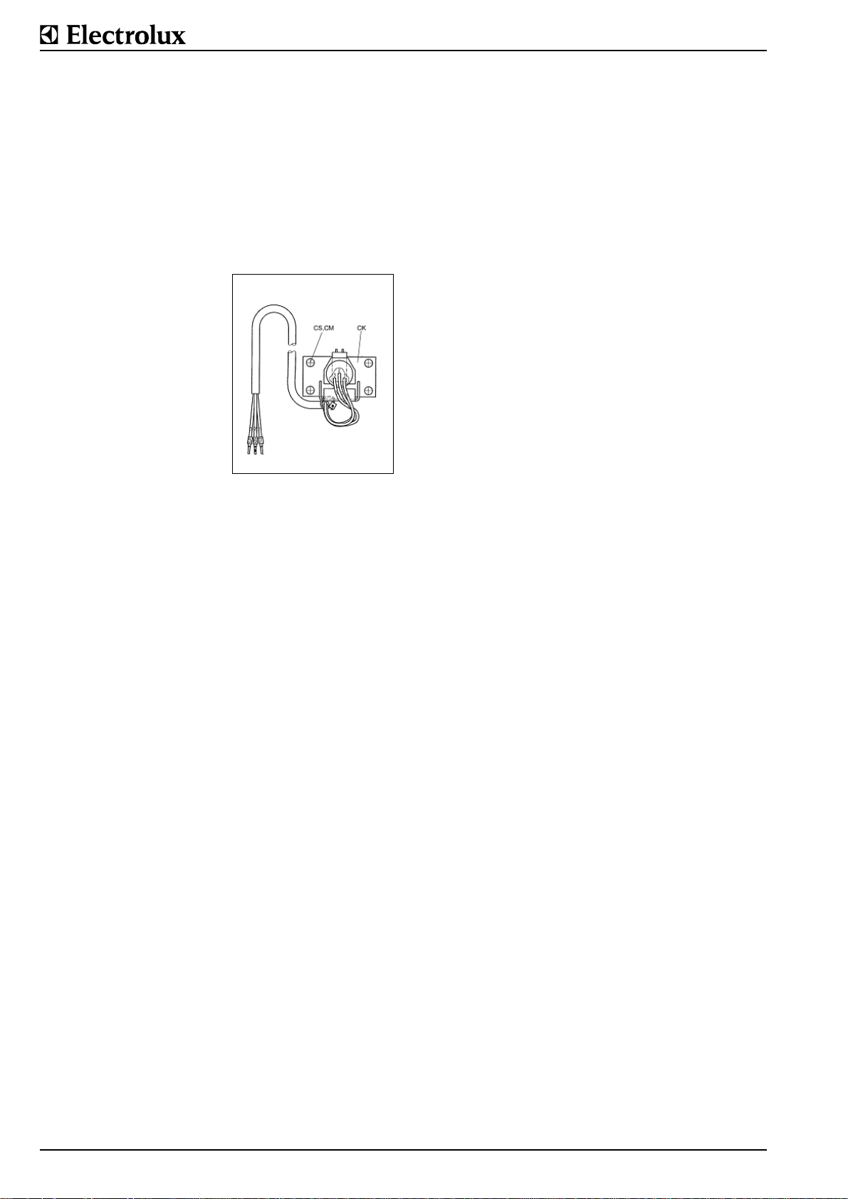
Take off the support plate (TB) by removing 4 nuts from the
front. Take off the complete switch (CK) by removing the 2
nuts (CM) and screws (CS) resp 2 screws (CA) from the support plate.
Installation
Proceed as described under "Removal" but in the reverse
order. Ensure that the electrical connections are made as
shown. The switch knob must be pressed firmly against the
front panel to ensure that the seal bears evenly all round.Version 1999To exchange a switch against the version 1999 proceed as following: Install a new support plate (TB), use 4
screws (CS,CM) to fasten the switch. The flat part of the shaft
must be positioned downwards.
Fig. 12 Tilting motor, switch
Page 18 62.9694.03
Page 20
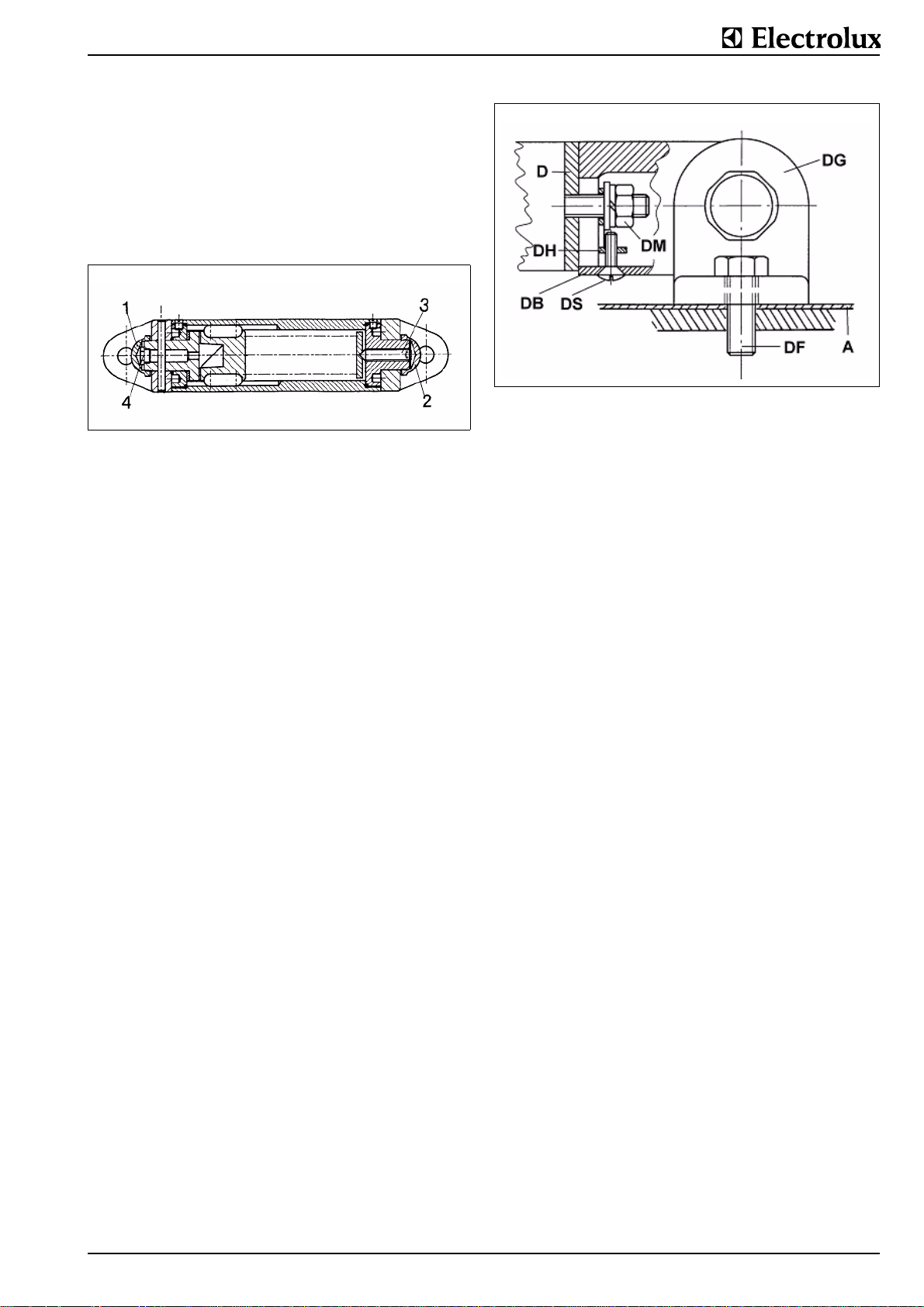
5.4 LID (D)
5.4.1 LID HINGE (DG)
Servicing
After a lengthy period of use, the lid may prove stiff to operate.
This can be remedied by lubricating it.
Procedure:
Close the lid (D). Unscrew the domed nut (1) on the left-hand
side. Inject approx. 20 grams of special fittings grease through
the nipple (4) with a grease gun. Refit the domed nut (1). Open
and close the lid several times (do this smoothly) with the
Lid hinge (DG)
Fig. 13 Lid
Adjustment
The lid hinges are supplied lightly pretensioned and can be
adjusted subsequently. Unscrew the nuts (2) on the right when
viewed from the front.
Insert the long side of a 4 mm Allen key into the screw (3).
With the lid open, increase the tension by turning the key
clockwise. After each turn, check whether the lid is counterbalanced or not. If not, continue to increase tension. Approximately 8 - 10 turns are possible until the next highe st capacity
is reached. If the lid hinge blocks when the lid is being closed,
turn the Allen key counterclockwise and reduce the tension.
The correct tension is achieved when the lid remains open on
its own at an angle of ³ 15° and closes by itself due to its own
weight at an angle of < 15°. After the lid has been correctly
adjusted, the nipple (4b) and the nut (2) is screwed on again.
Removal
Lids may be fitted with one or two hinges. The procedure is the
same in both cases. Fully open the lid (D). Remove the screw
(DS) as well as the plate (DB). Unscrew the two nuts (DM) and
remove the washers as well as the retaining plate (DH). The lid
is now separated from the lid hinge. The lid hinge can be
removed from the cover plate (A) by removing the two screws
(DF) with the washers.
Installation
The lid hinges are supplied in the "Lid open" position. A lid
hinge may only be moved when it is fixed in position. If it is not
fixed in position, it may cause injury by suddenly springing
back if incorrectly handled. The front of the left-hand mount
has a marking (capacity). This figure must point to the front
when the lid hinge is fitted. First screw the lid hinges to the
cover plate but do not tighten them yet. Then fit the lid to the
hinges in the open position. Tighten the nuts (DM) firmly. Align
the lid to the cooking pan and then tighten the screws (DF)
fully.
Fig. 14 Lid, installation
62.9694.03 Page 19
Page 21
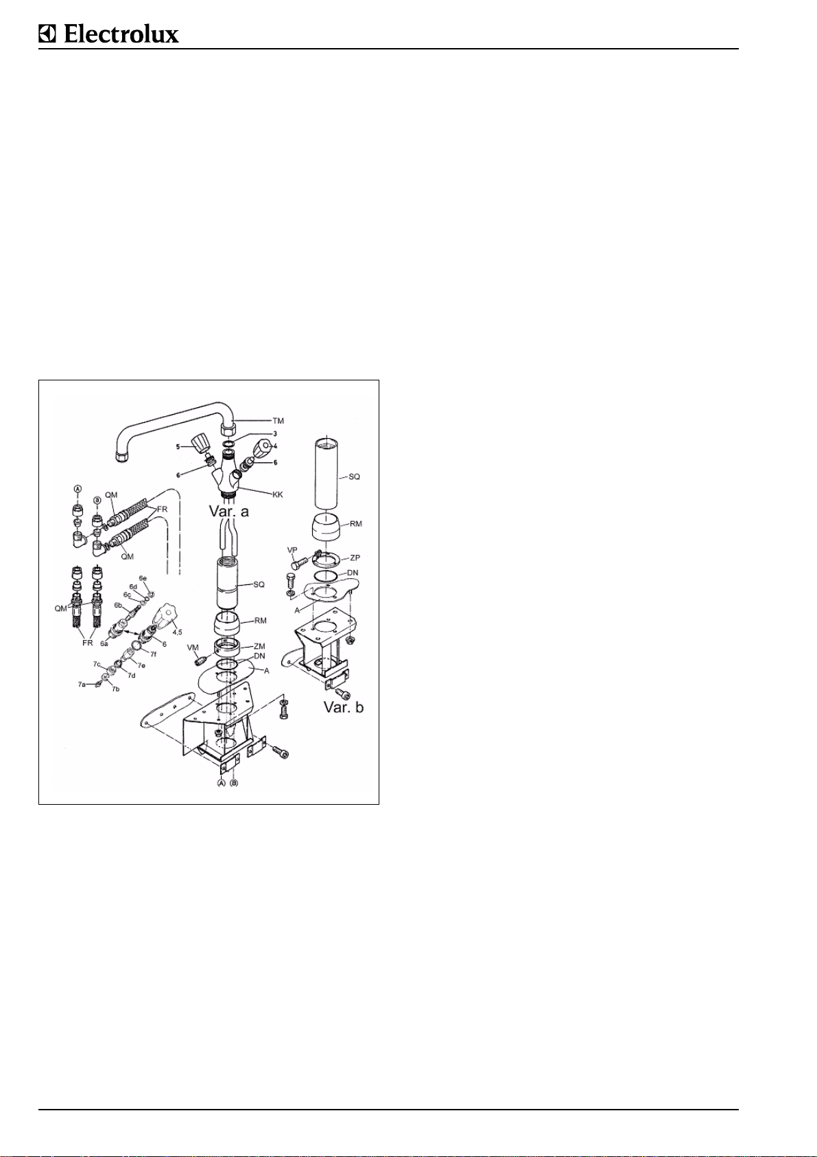
5.5 MIXING UNIT Maintenance
Check all sealed points and joints for any leakage. Replace
seals if necessary.Descale the spray head.
Removal
Unscrew the swiveling arm (TM) with its seal from the valve
body (KK). Remove the cover (A) from the unit in accordance
with § 5. Disconnect the flexible hoses (FR) with their seals
from the screw connections (QM).
Variant a: Slacken the screws (VM) on the ring (ZM).
Variant b:Slacken the screw (VP) on the ring (ZP).
Withdraw the column (SQ) from the cover spigot. Remove the
collar (RM) from the column. Care for the seal (DN). Further
dismantling: pull off the valve knobs (cold water = blue and hot
water = red). Unscrew the valve inserts with the integral seals.
Parts (3) to (7).
Installation
Proceed as above but in the reverse order. N.B.: twist the mixing unit to the correct position, i.e. both valve knobs should
face forward.
Fig. 15 Mixing unit
Page 20 62.9694.03
Page 22
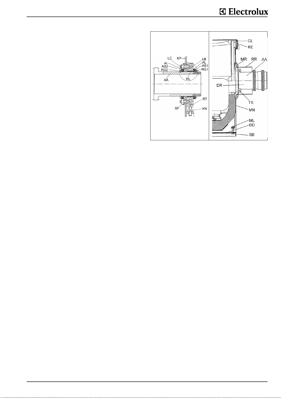
5.6 PAN COMPARTMENT Removal
On both sides: take off the covers (A) and the switch panels
(F) in accordance with §5. Left-hand side: take off the cover
and the tilting control system in accordance with § 5.3. Support
the pan at the rear with a balk of timber and disconnect the tilting drive at the front by removing the sheet nuts (BA) and the
bolt (MA). Disconnect the stirrer motor electric cable from the
motor protection switch (MT). Take the tilting handle (KH) off
the pivot in accordance with § 5.3. Right-hand side: take off
the electrical connections for the electric heating, deaeration
valve and the 3 sensors from the contactors or the front panel.
Both sides: Remove the inner walls (W) of the console cladding by undoing 2 nuts inside in the upper part and 2 screws
below. Then, on each side, take out the 4 screws (SF) through
which the two bearing parts (LB) and (LC) are clamped to the
console panels (KP). Withdraw the pan upwards out of the
supports in the consoles, either by driving a lift truck upon
which a car tire has been placed under the pan and raising it or
with a forklift truck by lifting it on a rope looped around the pivots. The inner walls (W) can then be taken off together with the
pivot collars (MR).
Installation
Proceed as described under "Removal" but in the reverse
order. The left-hand bearing is a rigid bearing and has only one
ring (AS) on both sides.Pivot height adjustment
The height of the appliance's tilting pivot (AA) can be adjusted
as follows:-Slacken the 4 screws (SF) on the bearing.-Slacken
the lock nut (KN).-Screw the screw (RT) in or out as required
to obtain the correct height.-Tighten the lock nut (KN).Retighten the 4 screws (SF).
5.6.1 BEARINGS, PIVOTS
Removal
Remove the retaining ring (RG1) using the special pliers and
pull the washer (AS1) as well as the axial bearing elements
(AL) off the pivot shaft (AA). Take off the bearing part (LB) with
the radial bearing (RL), plus the flange (LC) as well as the rear
washers (AL), the ring (AS2) and the retaining ring (RG2). Further dismantling is done by taking out the 4 screws (TS). This
allows the following parts to be removed one after the other:
the tube (RR), the pivot shaft (AA), the spacer (DR) and, from
the jacket (MN), the collar (MR).
Installation
Proceed as described under "Removal" but in the reverse
order. The left-hand pivot bearing is a rigid bearing and only fitted with a ring (AS1) and (AS2) on both sides. The axial tolerances of the pan are equalized on the right-hand bearing. A
total of 6 rings (AS) are used; these may consist of 3 rings on
both sides or, dependent on the situation, 2 may be used on
one side and 4 rings on the other side.
Right-hand pivot bearing
Fig. 16 Pan
PAINT FINISH
The surface of the appliance that is directly affected by the
heating (the lower surface of the cooking space) receives a
special black finish at the factory. This finish protects the floor
from corrosion and improves the flow of heat in the cooking
space. To repair damaged areas of the finish, the orig inal finish is available in the form of an aerosol. The areas to be
treated must be dry, clean and free of grease. Drying time is
approximately 1 hour.
Paint finish: Dupli-Color, Supertherm 800°C, toxic classification 5. Available from : Kurt Vogelsang AG, CH-8604 Volketswil or from specialist suppliers.
5.6.2 CASING (MN)
Removal
After dismantling the pivots (AA), the jacket (MN) can be withdrawn from the pan flange (KE) by taking off the two nuts (ML).
Installation
The rubber ring (GL) is inserted into the groove on the jacket
(MN) and, wetted with gliding vaseline, pushed into the pan
flange (KE). Push the rods (BE) through the rails (KR), connect
them to the pan link plates (LK) and tighten with the nuts (ML).
62.9694.03 Page 21
Page 23
5.7 APPENDIX UNIVERSAL CONTROL DESCRIPTION OF PARAMETERS
PNr. Parameter number NA Not yet activated
GS Default setting Z, D Value of display
B Setting range X Parameter value to be programmed in
PNr. GS B Designation Description / Setting
. .1. 0 0/1 Temperature display 0 = display in °F
. .2. 0 0/1 Start of timer 0 = timer starts after reaching the
. .3. 1 0/1 Correction of the displayed actual
. .4. 0 0/1 Energy optimization system EO 0 = EO out of operation
. .5. 1 0/1 Deaeration of the jacket 0 = deaeration out of operation
. .6. 1 0/1 Heating with tilting 0 = heating works when pan is
. .7. 1 0/1 Excess temperature safety ther-
. .8. 0 0/1 Pressostat in the jacket 0 = pressostat out of operation
. .9. 0 0/1 Pressure switch in the food com-
.1.0. 1 0/1 Starting time 0 = delay time setting; the cook-
.1.1. 1 0/1 Cooking with SOFT setting 0 = SOFT setting out of operation
.1.2. 0 0/1 Automatic steam condensation 0 = steam condensation out of
.1.3. 1 0/1 Buzzer 0 = buzzer out of operation
.1.4. 0 0/1 Setting of max. food temperature 0 = setting is possible above the
.1.5. 0 0/1 Actual value of max. food temper-
.1.6. 1 0/1 Lid position while tilting 0 = tilting is possible only when lid
.1.7. 1 0/1 Function of stirring system and lid
.1.8. 1 0/1 Function of stirring system and
.1.9. 1 0/1 Power settings and boiling tem-
value of the food temperature
mostat 0 = safety thermostat out of oper-
partment
ature
position
tilting switch
perature
1 = display in °F
setting temperature
1 = timer starts instantly after
starting the cooking process
0 = exact display of the actual
value of the food temperature
1 = difference between actual
value and setting is halved
1 = EO in operation
1 = deaeration in operation
tilted
1 = heating is switched off when
pan is tilted
ation
1 = safety thermostat in operation
1 = pressostat in operation
0 = switch out of operation
1 = switch in operation
ing process starts after setting time runoff
1 = real time setting; the cooking
process starts with input
clock time
1 = SOFT setting in operation
operation
1 = steam condensation in opera-
tion
1 = buzzer in operation
calculated boiling temperature
1 = setting is only possible up to
the calculated boiling temperature
0 = no limitation of the display for
the food temperature
1 = the display arrives only the
calculated boiling temperature
is open
1 = tilting is independent of the lid
position
0 = stirring is only possible when
lid is closed
1 = stirring is independent of the
lid position
0 = stirring is dependent on tilting
switch actuation1 = stirring is
independent of tilting switch
actuation
0 = no power settings above boil-
ing temperature possible
1 = power settings possible
above boiling temperature
PNr. GS B Designation Description / Setting
.2.0.NA0 0/1 Dependence between power set-
.2.1. 1 0/1 Electric supply frequency 0 = 60 Hz
.2.2. 0 0/1 Electric supply frequency meas-
.2.3. 1 0/1 Reduction of undulation 0 = reduction out of function
.2.4. 0 0/1 Kind of heating 0 = electrically heated
.2.5. 1 0/1 Reduction of flicker 0 = flicker disturbances will not be
.2.6. 1 0/1 Modem connection 0 = modem connection switched
.2.7. 1 0/1 Display of the power settings 0 = display only of the actual tem-
.2.8. 0 0/1 D ual-function control for3-step
.2.9. 1 0/1 Deaeration sensor of the jacket 0 = sensor in front of the deaera-
.3.0. 0 0/1 Power setting function of motor
.3.1. 0 0/1 HOLD function 0 = HOLD switched off
.3.2. 0 0/1 HACCP function 0 = HACCP switched off
.3.3. 0 0/1 Printer function 0 = Printer switched off
.3.4. 0 0/1 Stirrer function with open lid 0 = Stirring system switched off
.3.5. 0 0/1 Function of the steam condensa-
.4.9. 0 0 - 5 Applianc e code 0 = kettle electrically heated,
.5.0. 1 0 - 3 Appliance type 0 = pressure boiling pans
.5.2. 1 1 - 32 Communication address 1-32 = addresses for remote con-
.5.3. 10 0 - 50 Switching delay time of the con-
.5.4. 4 1 - 4 Quantity of switching steps Number of contactors to be
.5.5. 5 0 - 40 Release temperature for the timer Temperature difference in °F
tings and food temperature
urement
motor valve
valve
tion sensor
tactors
0 = the distribution of the power
settings is dependent on temperature
1 = over the whole range the dis-
tribution of the power settings
is independent of temperature (standard control)
1 = 50 Hz
0 = the programmed frequency
will be measured automatically and if necessary corrected
1 = the frequency will be not
measured
1 = reduction in function
1 = gas heated
considered
1 = reduction of flicker distur-
bances according to regulations
off
1 = modem connection switched
on
perature
1 = additional display of the
power settings above the
boiling temperature
0 = function switched off
1 = function switched on
tion valve out of function
1 = sensor in front of the deaera-
tion valve in function
0 = Progressive function of power
setting switched off
1 = Progressive function of power
setting switched on
1 = HOLD switched on
1 = HACCP switched on
1 = Printer switched on
1 = Stirring system switched on
0 = Sensor switched off
1 = Sensor switched on
max. 4 contactors, 3 temperature sensors
1 = kettle directly steam-heated,
with 3-step motor valve, 1
temperature sensor
2 = kettle directly steam-heated,
with solenoid valve, 1 temperature sensor
3 = pan electrically heated, max.
4 contactors, 2-3 temperature
sensors
1 = normal boiling pans
2 = pans with digital operation
3 = pans with analogous opera-
tion (potentiometer)
trol via PC
Time interval between 2 contactors when switched on/off in
series (1 unit = 100 ms, 50 = 5
seconds)
switched on/off in series
between setting and actual value
for starting the timer
Page 22 62.9694.03
Page 24
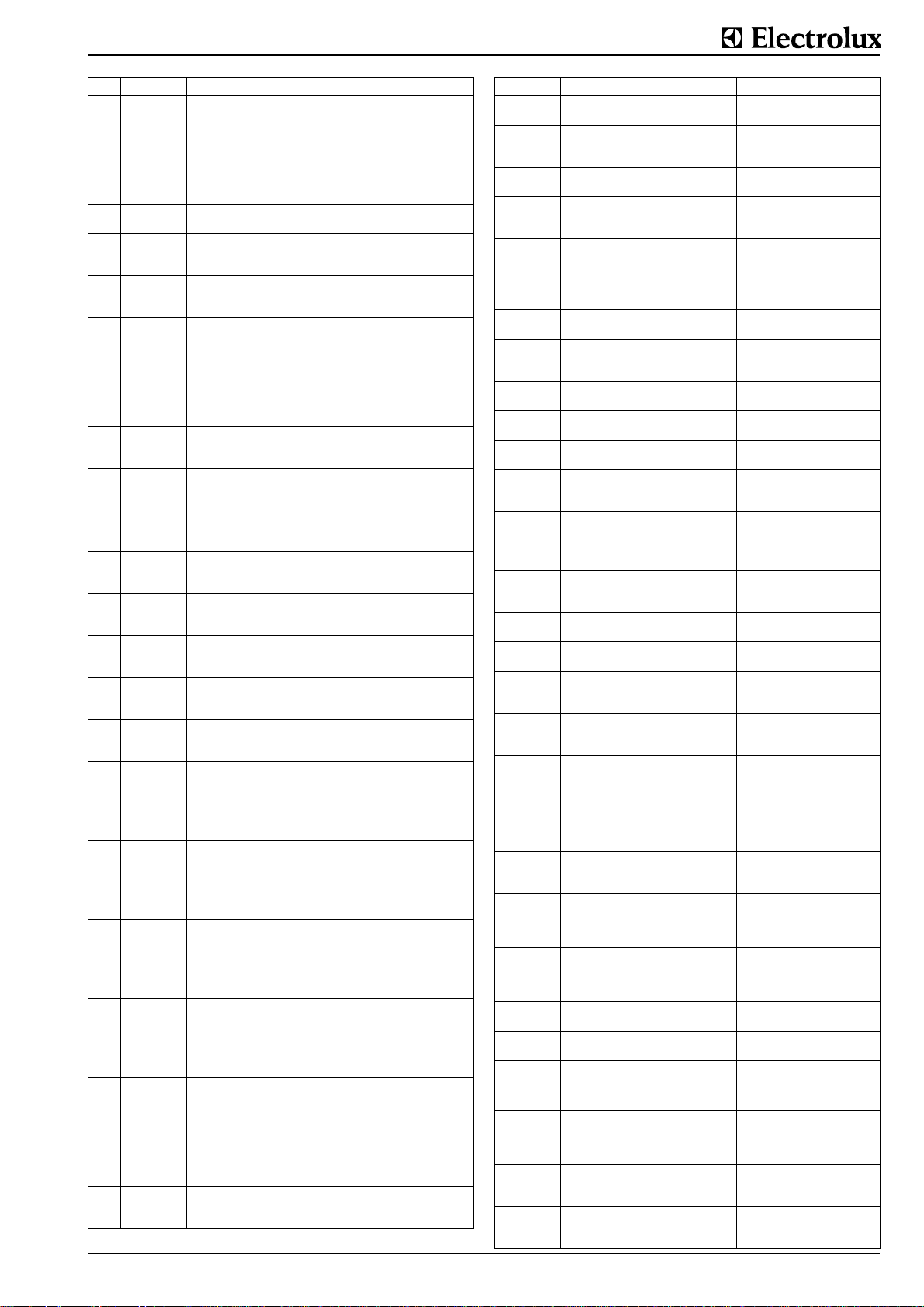
PNr. GS B Designation Description / Setting
.5.6. 5 0 - 40 Release temperature for the lamp
.5.7. 1 0 - 40 Hysteresis of deaeration valve of
.5.8. 15 0 - 20 Openings of the deaeration valve Max. number of valve openings
.5.9. 2 0 - 25 Hysteresis of control in reference
.6.0. 1 0 - 25 Hysteresis of control in reference
.6.1. 1 0 - 25 Hysteresis of control in reference
.6.2. 30 0 -
.6.3. 2 0 -
.6.4. 4 0 -
.6.5. 6 0 -
.6.6. 4 0 -
.6.7. 8 0 -
.6.8. 40 0 -
.6.9. 5 0 -
.7.0. 0 0 -
.7.1. 0 0 -
.7.2. 0 0 -
.7.3. 0 0 -
.7.4. 0 0 -
.7.5. 10 0 -
.7.6. 1 0 -
.7.7. 10 0 -
signalizing heating
the jacket
to the jacket sensor
to the food sensor
to the food sensor
Max. temperature for switching
100
off the heating
Lower temperature band width 1
100
for the jacket sensor
Lower temperature band width 2
100
for the jacket sensor
Lower temperature band width 3
100
for the jacket sensor
Upper temperature band width 1
100
for the jacket sensor
Upper temperature band width 2
100
for the jacket sensor
Upper temperature band width 3
100
for the jacket sensor
Starting the ramp 1(only for 3-
100
step motor valve)
Starting the ramp 2(only for 3-
100
step motor valve)
Temp. definition of ramp 1 for
100
normal cooking (only for 3-step
motor valve)
Temp. definition of ramp 1 for
100
SOFT cooking (only for 3-step
motor valve)
Temp. definition of ramp 2 for
100
normal cooking (only for 3-step
motor valve)
Temp. definition of ramp 2 for
100
SOFT cooking (Only for 3-step
motor valve)
Integration period (only for 3-step
100
motor valve)
Hysteresis of the food sensor in
100
reference to steam condensation
Duration of steam condensation Max. duration of steam conden-
240
Difference in °F between setting
and actual temperature for the
heating lamp changing from intermittently to continuous shining
Hysteresis of temperature margin for "start deaeration cycle"
below which a new deaeration
cycle starts
during heating-up
Difference in °F between jacket
sensor and setting temperature
for starting the heating again
Difference in °F between food
sensor and setting temperature
for starting the heating again
Difference in °F between the pan
bottom sensor and setting temperature for starting the heating
again
Max. difference in °F between the
pan bottom and setting; only in
function if appliance is controled
by the food sensor
Temperature fringe range in °F of
the lower band 1; used for flicker
algorithm
Temperature fringe range in °F of
the lower band 2; used for flicker
algorithm
Temperature fringe range in °F of
the lower band 3; used for flicker
algorithm
Temperature fringe range in °F of
the upper band 1; used for flicker
algorithm
Temperature fringe range in °F of
the upper band 2; used for flicker
algorithm
Temperature fringe range in °F of
the upper band 3; used for flicker
algorithm
Temperature margin % between
setting and actual value when
starting ramp 1
Temperature difference %
between setting and actual value
when starting ramp 2
Temperature margin % of the difference between setting and
actual value of food temperature
when the temperature in ramp 1
for normal cooking is defined as
to be reached
Temperature margin % of the difference between setting and
actual value of food temperature
when the temperature in ramp 1
for SOFT cooking is defined as to
be reached
Temperature margin % of the difference between setting and
actual value of food temperature
when the temperature in ramp 2
for normal cooking is defined as
to be reached
Temperature margin % of the difference between setting and
actual value of food Temperature
when the temperature in ramp 2
for SOFT cooking is defined as to
be reached
Difference in °F between setting
and temperature margin for the
food sensor below which the
period of integration starts again
Difference °F between actual
value and temperature margin
(PNo. 1.4.3.), for opening the
valve of condensation again.
sation. After this time the valve
keeps closed.
PNr. GS B Designation Description / Setting
.7.8. 30 0 -
.7.9. 25 0 -
.8.0. 2 0 - 20 Temperature correctionsee PNo.
.8.1. 1.5 0 - 10 Temperature correctionsee PNo.
.8.2. 5 0 -
.8.3. 50 0 -
.8.4. 0 0 -
.8.5. 80 0 -
.8.6. 30 0 -
.8.7.
40 0-600
.8.8. 160 0-600
.8.9. 160 0-600
.9.0. 160 0-600
.9.1. 160 0-600
.9.2. 160 0-600
.9.3. 86 0-130 Start of deaeration cycle
.9.4. 104 0-130
.9.5. 800 0-999
.9.6. 200 0-400 Max. food temperature
.9.7. 300 0-400
.9.8. -50
.9.9. 180 0-250
1.0.0. 0
1.0.1. 0
1.0.2. 110 0-140
1.0.3. 122 0-140
1.0.4. 50 0-300
1.0.5. 100 0-300
1.0.6. 50 0-300
1.0.7. 100 0-300
Duration of periods of the power
240
levels
Power level L1 Min. action time % of level L1 in
100
. . 3.
. . 3.
Temperature correctionsee PNo.
200
. . 3.
Influence of height above sea
800
level on boiling temperature
Cooking time during boiling in
250
HOLD function
Opening time of the deaeration
999
valve
Min. closing time of the deaera-
999
tion valve
Standstill of stirrer during oscillat-
ing 1
Running time of stirrer during
oscillating 1
Running time of stirrer during
oscillating 1
Standstill of stirrer during oscillat-
ing 2
Running time of stirrer during
oscillating 2
Running time of stirrer during
oscillating 2
Temperature for opening the
deaeration valve
Allowed amount of openings of
the deaeration valve
Max. jacket resp. bottom temperature
-60
bis
Limit of vacuum pressure display
+200)
Max. jacket pressure to release
alarm
-20
Measuring inaccuracy correction
bis
of the food temperature sensor
+20
-20
Measuring inaccuracy correction
bis
of the jacket temperature sensor
+20
Setting of jacket temperature sensor for normal cooking
Jacket temperature for normal
cooking setting
Correction of the temp. difference
at the lower fixpoint of the bottom
temperature Ty = 122°F (50°C)
Correction of the temperature difference at the upper fixpoint of
the bottom temperature Ty =
212°F (100°C)
Lower fixpoint for trimming the
bottom temperatureTx = 122°F
(50°C)
Upper fixpoint for trimming the
bottom temperature Tx = 212°F
(100°C)
Definition of the duration of period
sec. of levels L1-L9
respect to the duration of the
period
Duration of period sec. to switchoff the temperature correction
Extent of decrement in °F per
time window for temperature correction (duration see PNo. . 80).
Duration of period sec. to calculate the temperature derivation
Input of height above sea level of
the installation site in 10 m (500
m above sea level. = 50).
Cooking time during boiling temperature
Opening time in 100 ms of the
jacket deaeration valve for each
deaeration cycle
Min. closing time in 100 ms of the
jacket deaeration valve
Standstill period in 100 ms in
oscillating level 1
Running time in 100 ms clockwise rotation in oscillating level 1
Running time in 100 ms counterclockwise rotation in oscillating
level 1
Standstill period in 100 ms in
oscillating level 2
Running time in 100 ms clockwise rotation in oscillating level 2
Running time in 100 ms counterclockwise rotation in oscillating
level 2
Temperature in °F below which
the deaeration cycle starts
Temperature in °F opening the
deaeration valve
10 x display value = admissable
amount of openings until alarm
display A31 is released
Max. temperature in °F (at the
analogous input J15) releasing
alarm E6
Max. temperature in °F (at the
analogous input J16) releasing
alarm E7
Pressure in 0.01 bar (01.5psi),
above which display is active;
below the programmed value display shows P0.00
Jacket pressure in 0.01 bar
(01.5psi), releasing alarm E80 =
no alarm will be released
Offset temperature in °F for the
measuring inaccuracy correction
of the temperature sensor (at the
analogous input J15)
Offset temperature in °F for the
measuring inaccuracy correction
of the temperature sensor (at the
analogous input J16)
Temperature in °F of lower limit
for normal cooking setting
Temperature in °F of upper limit
for normal cooking setting
±
Δ
T correction °F at bottom
temp. of 122°F (50°C) (refer to
"Trimming of temperature measurement").
±
Δ
T correction °C at bottom
temp. of 212°F (100°C) (refer to
"Trimming of temperature measurement").
Input of bottom temperature
122°F (50°C) (refer to "Trimming
of bottom sensor").
Input of bottom temperature
212°F (100°C) (refer to "Trimming
of bottom sensor").
62.9694.03 Page 23
Page 25
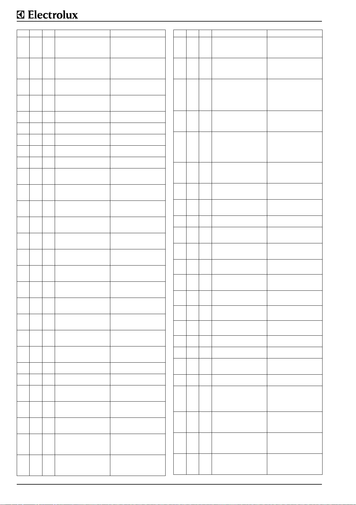
PNr. GS B Designation Description / Setting
±
Δ
1.0.8. 50 0-300
1.0.9. 100 0-300
1.1.0. 50 0-300
1.1.1. 100 0-300
1.1.2. 106 0-140
1.1.3. 115 0-140
1.1.4. 70 0-140
1.1.5. 100 0-140
1.1.6. 140 0-200
1.1.7. 15 0-999
1.1.8. 10 0-999
1.1.9. 5 0-999
1.2.0. 120 0-999
1.2.1. 60 0-999
1.2.2. 20 0-999
1.2.3. 15 0-999
1.2.4. 10 0-999
1.2.5. 5 0-999
1.2.6. 120 0-999
1.2.7. 60 0-999
1.2.8. 20 0-999
1.2.9. 20 0-300 Period of PI control unit
1.3.0. 15 0-150 Error of PI control unit
1.3.1. 10 0-300
1.3.2. 300 0-999
1.3.3. 15 0-999
1.3.4. 10 0-499
1.3.5. 2 0-499
Correction of error of measurement when measuring the food
Ty = 122°F (50°C)
Correction of error of measurement when measuring the food
Ty = 212°F (100°C)
Real food temperature Tx =
122°F (50°C)
Real food temperature Tx =
212°F (100°C)
Jacket temperature setting for
SOFT cooking
Jacket temperature setting for
SOFT cooking
Actual food temperature setting
for SOFT cooking
Actual food temperature setting
for SOFT cooking
Max. working pressure in the
jacket
Flicker reduction t-min upper
band 1
Flicker reduction t-min upper
band 2
Flicker reduction t-min upper
band 3
Flicker reduction t-max upper
band 1
Flicker reduction t-max upper
band 2
Flicker reduction t-max upper
band 3
Flicker reduction t-min lower band
1
Flicker reduction t-min lower band
2
Flicker reduction t-min lower band
3
Flicker reduction t-max lower
band 1
Flicker reduction t-max lower
band 2
Flicker reduction t-max lower
band 3
Floating time for 3-step motor
valve
Proportional correction of the PI
control unit
Integral correction of the PI control unit
Increment of the food temperature setting ramp 1 for normal
cooking
Increment of the food temperature setting ramp 1 for SOFT
cooking
T correction in °C for food temperature 122°F (50°C) (see chapter "trimming of temperature
measuring").
±
Δ
T correction in °C for food temperature 212°F (100°C) (see
chapter " trimming of temperature
measuring")
Input of food temperature 122°F
(50°C) (see chapter " trimming of
temperature measuring")
Input of food temperature 212°F
(100°C) (see chapter " trimming
of temperature measuring")
Temperature in °F setting of
lower limit for SOFT cooking
Temperature in °F setting of
upper limit for SOFT cooking
Temperature in °F setting of
lower limit for SOFT cooking
Temperature in °F setting of
upper limit for SOFT cooking
Max. admissable overpressure in
0.01 bar (01.5psi) in the jacket
Min. time sec. the jacket tempera-
ture has to remain in the upper
band 1
Min. time sec. the jacket temperature has to remain in the upper
band 2
Min. time sec. the jacket temperature has to remain in the upper
band 3
Min. time sec. the jacket temperature can remain in the upper band
1
Min. time sec. the jacket temperature can remain in the upper band
2
Min. time sec. the jacket temperature can remain in the upper band
3
Min. time sec. the jacket temperature has to remain in the lower
band 1
Min. time sec. the jacket temperature has to remain in the lower
band 2
Min. time sec. the jacket temperature has to remain in the lower
band 3
Min. time sec. the jacket temperature can remain in the lower band
1
Min. time sec. the jacket temperature can remain in the lower band
2
Min. time sec. the jacket temperature can remain in the lower band
3
Time period sec. of the incrementable control unit
Max. error in °F of the incrementable control unit
Min. floating time in 0.1 sec. for
opening resp. closing the 3-step
motor valve
Setting time in 0.1 sec. for max.
proportional correction of the 3step motor valve
Setting time in 0.1 sec. for max.
integral correction of the 3-step
motor valve
Temperature in 0.05°F for the
increment period of the food temperature setting for normal cooking (for period time, see 1.2.9.)
Temperature in 0.05°F for the
increment period of the food temperature setting for SOFT cooking (for period time see 1.2.9.)
PNr. GS B Designation Description / Setting
1.3.6. 2 0-499
1.3.7. 1 0-499
1.3.8. 33 0-600
1.3.9. 111 0-300
1.4.0. 250 0-300
1.4.1. 30 0-600
1.4.2. 0 0-600
1.4.3. 102 0-300
1.4.4. 110 0-300 Max. food setting temperature
1.4.5. 110 0-300 Max. food sensor temperature
1.4.6. 110 0-120
1.4.7. 0
1.4.8. 20 0-150
1.4.9. 3
1.5.0. -1
1.5.1. 1
1.5.2. 20 0-120
1.5.3. 60 0-999
1.5.4. 0 0-120
1.5.5 50 0-100 Min. food sensor temperature
1.5.6. 5 0-50
1.5.7. 70 0-100
1.5.8. 15 0-100)
1.5.9. 0
Increment of the food temperature setting ramp 2 for normal
cooking
Increment of the food temperature setting ramp 2 for SOFT
cooking
Running time of the 3-step motor
valve
Changing temperature from bottom to food sensor
Temperature switching margin for
the food sensor
Max. on-transition time of the
heaters
Min. switched-off time of the heaters
Temp. switching margin for steam
condensation
Max. setting temperature for
pressure cooking
-20
q of SDIRHOFF = SDIRH-
bis
(q+m*dT/dt)
+40
m of SDIRHOFF = SDIRH(q+m*dT/dt) for food sensor
-40
p of SDIRHON = SDIRH-
bis
(1+p/100)-ISDIRH
+40
-50
bis
Max. difference of TDIRH for "ON
+50
-50
Min. difference of TDIRH for
bis
"OFF
+50
Min. duration of heatings
switched on
Min. off-period after ignition failure
Delay of heating-on during power
setting
Temperature band width of control print
Max. admissible temperature of
the control print
Difference between bottom sensor and setting during SOFT
function
-30
Difference between boiling tem-
bis
perature and setting during the
+30
function power setting and HOLD
Temperature in 0.05°F for the
increment period of the food temperature setting for normal cooking (for period time, see 1.2.9.)
Temperature in 0.05°F for the
increment period of the food temperature setting for SOFT cooking (for period time, see 1.2.9.)
On-transition time sec. for complete opening resp. closing of the
3-step motor valve for a nominal
running time = 30 sec.; if the run-
ning time is LZ
ting should be approx. 1.1 LZ.
Nominal temperature value in °F
at which the control system
switches from the bottom- to the
food sensor and vice versa
Setting temperature °F of the
food sensor at which the heating
power is reduced by clock pulses.
This prevents the rod heaters
from overheating during long simmering periods.
Max. on-transition time in sec. of
the heatings. This limitation protects the heaters from overheating.
Min. switched-off time of the heatings. This limitation protects the
heaters from overheating.
Defines the temperature in °F at
which the steam condensation
valve is switched off or on
Max. food setting temperature in
°F which can be set by the user
Max. temperature in °F of the
food sensor in the range of the
power steps L1 - L9
Max. setting temperature °F for
pressure cooking, which can be
set by the user
Reduction of undulation of the
actual temperature
Reduction of overshooting of the
actual temperature during heating
up for food sensor
Reduction of undulation of the
actual temperature
"Reduction of undulation of the
actual temperature
"Reduction of undulation of the
actual temperature
Min. switched-on time in sec. of
the gas burner
Min. off-period in sec. after the
2nd ignition failure of the burner
Defines the delay time of the
heating-on times during power
setting (gas appliances)
Min. food setting temperature in
°F which can be set by the user
Temperature band width in °F
below the max. admissible temperature of the control print, in
which the print can still work for 1
hour
Upper limit of the max. admissible
temperature °F of the control
print, above which the control unit
switches off immediately
Defines the max. difference
(upwards) between bottom temperature and setting during SOFT
cooking
Difference °F between calculated
boiling point and setting for 3-step
motor valves during the function
power setting and HOLD
30 sec. the set-
Page 24 62.9694.03
Page 26
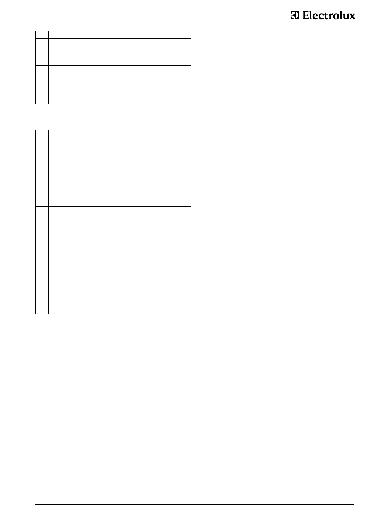
PNr. GS B Designation Description / Setting
Difference in °F between calcu-
1.6.0. 3
1.6.1. 40 0-150
1.6.2. 85 0-200
-20
bis
+20
Changing temperature difference
m of SDIRHOFF = SDIRH(q+m*dT/dt) for the bottom sensor
Upper temperature limit of deaeration
lated boiling temperature and
actual food temperature, at which
temperature control changes to
power step regulation
Reduction of overshooting of the
actual temperature during heating
up for the bottom sensor
Upper limit of max. temperature
in °F at the sensor in front of the
deaeration valve stopping the
deaeration cycle
Inquiry of cumulated data
PNr. GS B Designation Description; Z,
D = Value of display
1.6.3. 0
1.6.4. 0
1.6.5. 0
1.6.6. 80 0-300 Last setting of temperature
1.6.7. 30 0-600 Last setting of cooking time
1.6.8. 5
1.6.9. 0
1.7.0. 0 0-999 Last failure code display
1.7.1. 0 0/1 Last deaeration
0 39'999)Time meter for heating "on
0 39'999)Time meter for appliance "on
0 -
Counting of deaerations carried
9'999)
out
0-
Last setting of starting time for
6000
operation with real and delay time
0 -
Last setting of starting time for
24*60
operation with real time
"10xZ = total time h, during which
one or more heatings have been
switched on
"10xZ = total time h, during which
the appliance has been switched
on (control switch on)
Z = total number of complete
deaeration cycles = connection
with A31 and PNo. .9.5.
D = last done setting of temperature in °F before the last supply
interruption
D = last done setting of cooking
time in min. before the last supply
interruption
D = Last done setting of starting
time in min. before the last supply
interruption
D = last done setting of starting
time before the last supply interruption; the displayed value is
mathematically coded and does
not give the right value (hours)
D = last existing failure code display before the last supply interruption (failure code without letter
in front)
0 = before the last switch-off no
complete deaeration was carried out
1 = before the last switch-off a
complete deaeration was carried out
62.9694.03 Page 25
 Loading...