

Electrolux EURO OVEN Service Manual
Edition:
SERVICE MANUAL
© AEG Hausgeräte GmbH
Muggenhofer Straße 135
D-90429 Nürnberg
Germany
Fax +49 (0)91 1 323 1420
TSE - N
Publ.-Nr.:
599 50 72 16
685
12.99
EURO OVEN
EN
WOEC
Test program

- 2 -
TSE-N 12.99 A. B. 599 50 72 16 EN
Page
Contents 2
Safety instructions 3
1. General technical information 4
1.1 User technical data 4
Dimensions 4
1.2 Hot plate controls 5
Circuit diagram of energy regulator 1 5
Circuit diagram of energy regulator 2 5
1.3 Oven control 5
Circuit diagram of oven thermostat 5
Thermotronic (electronic oven control, WOEC) 5
1.4 WOEC test programmes and their application 6
Descriptions of programme 1 - 6 7 - 11
Fault-finding 12
2. Service instructions 13
Dismantling front glass oven door and door handle 13
Rubber gasket between air duct and switch panel 14
- 3 -
TSE-N 12.99 A. B. 599 50 72 16 EN
Attention
m Please observe the applicable safety requirements according to DIN/VDE 0701
(concerning repairs) and VDE 0700/ICE 355 respectively VDE 0860/IEC 65 (concerning
type of product)!
m Components to IEC or VDE guidelines! Only use components with the same
specification for replacement!
m Controls with MOS components use only components with the same specification.
m Observe MOS components handling instructions when servicing!
Recommendation for service repairs
m Use only original spare parts.
With components or assemblies accompanied with the Safety Symbol
only origi-
nal-spare parts are strictly to be used.
m Use only original fuse value.
m Pay attention to ratings and power data of components and protective devices.
m Safety compliance, parts of the product must not be visually damaged or unsuitable.
This is valid especially for insulators and insulating parts.
m Mains leads and connecting leads should be checked for external damage before
connection. Check the insulation!
m The functional safety of the tension relief and bending protection bushes are to be
checked.
m Thermally loaded solder pads are to be suck off and re-soldered.
m Ensure that the ventilation slots are not obstructed.
Safety instructions
- 4 -
TSE-N 12.99 A. B. 599 50 72 16 EN
1. General technical information
1.1 User technical data
Capacity / Voltage
Oven heater (heating element)
Heating element bottom 1000 W / 230 V
Heating element top 1000 W / 230 V
Heating element grill 1900 W / 230 V
Heating element circulating air 2400 W / 230 V
Fan
Motor circulating air 35 W / 230 V
Querstromlüfter 16 W / 230 V
Lighting
Oven lamp rear 25 W / 230 V
Oven lamp lateral 25 W / 230 V
Dimensions
appliances dimensions
Height mm 579
Width mm 592
Depth mm 566
Built in dimensions
Built in hight mm 579
Built in width mm 540
Built in depth mm 546
- 5 -
TSE-N 12.99 A. B. 599 50 72 16 EN
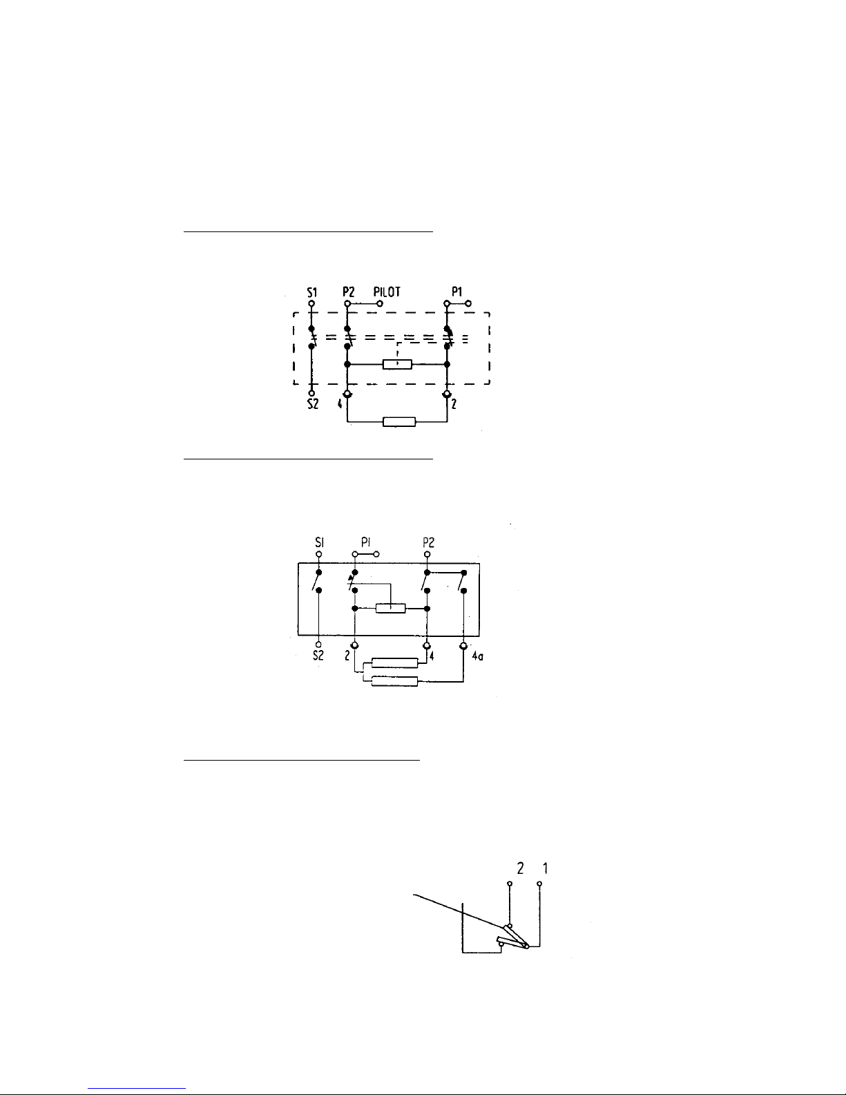
1.2 Hot plate controls
Circuit diagram of energy regulator 1
1.3 Oven control
Circuit diagram of oven thermostat
Some appliances are equipped with an electronic oven control (Thermotronic). See
Chapter 1.4 for further details.
Circuit diagram of energy regulator 2
Circuit diagram for “OFF” position
Circuit diagram for “OFF” position
Circuit diagram for “OFF” position
Can also be closed at left stop
 Loading...