

Electrolux EUROFLEC Service Manual
SERVICE MANUAL
REFRIGERATION
© ELECTROLUX ZANUSSI Publication No.
ELETTRODOMESTICI S.p.A. 599 34 85-04
VIA GIARDINI CATTANEO, 3 2001-09-05
I - 33170 PORDENONE (ITALY) ITZ/SERVICE/AA
Fax (0434) 394096
EUROFLEC
(EUROCOMBI version)

EUROFLEC 2/36

EUROFLEC 3/36
CONTENTS
1. Introduction...................................................................................................................................................5
1.1. Presentation .............................................................................................................................................5
1.2. EUROFLEC: total nofrost.........................................................................................................................6
2. Characteristics..............................................................................................................................................7
2.1. Dimensions and volumes.........................................................................................................................7
2.2. Technical characteristics..........................................................................................................................7
3. Diagrams .......................................................................................................................................................9
3.1 Functional diagram ...................................................................................................................................9
4. Components................................................................................................................................................12
4.1. Main components...................................................................................................................................12
4.2. UIB Display board ..................................................................................................................................14
4.3. MB Control and power board .................................................................................................................15
4.4. Foamed connectors seat .......................................................................................................................16
4.5. Fans .......................................................................................................................................................17
4.5.1. Operation with door closed..............................................................................................................17
4.5.2. Operation with door opened and compressor switched on.............................................................18
4.5.3. Operation with door opened and compressor switched off.............................................................18
4.6. Defrosting heaters..................................................................................................................................19
4.7. NTC Sensors..........................................................................................................................................19
4.8. Overheating protection...........................................................................................................................19
4.9. Freezer compartment light .....................................................................................................................19
4.10. Evaporator............................................................................................................................................20
4.11. Condenser............................................................................................................................................20
4.12. Flap-operated mechanical thermostat .................................................................................................20
5. Operation.....................................................................................................................................................21
5.1. Normal operation....................................................................................................................................21
5.2. Defrosting...............................................................................................................................................21
6. Control panel...............................................................................................................................................22
6.1. Switching the appliance on and off ........................................................................................................22
6.2. Door alarm .............................................................................................................................................23
6.3. Temperature alarm ................................................................................................................................23
6.4. “Rapid freezing” function........................................................................................................................23
6.5. NTC sensors failure ...............................................................................................................................24
7. Service mode ..............................................................................................................................................25
7.1. Selecting service mode..........................................................................................................................25
7.2. Signalling of faults..................................................................................................................................25
7.3. Separate activation of loads...................................................................................................................26
7.4. Checking the door switches...................................................................................................................26
7.5. Disactivation of service mode ................................................................................................................26
7.6 Days counter ...........................................................................................................................................26
8. Demo Mode .................................................................................................................................................27
8.1. Selecting Demo mode............................................................................................................................27
8.2. Main functions ........................................................................................................................................27
8.3. Exiting Demo mode................................................................................................................................27
9. Accessibility of components.....................................................................................................................28
9.1. Refrigerator compartment ......................................................................................................................28
9.2. Displaying board (UIB)...........................................................................................................................30
9.3. Freezer compartment.............................................................................................................................31
9.4. Glass shelves.........................................................................................................................................33
9.5. Air inlets .................................................................................................................................................33
9.6. Control and power board (MB)...............................................................................................................34
10. Main differences between the EUROCOMBI and the EUROFLEC model ...........................................35

EUROFLEC 4/36
EUROFLEC 5/36
1. Introduction
1.1. Presentation
The EUROFLEC is a new free-standing combined refrigerator, based on the EUROCOMBI model, but with
different versions produced in the Fuenmayor factory in Spain.
This appliance features a single compressor and a total no-frost system. The operating cycles are controlled
electronically. A flap-operated mechanical thermostat controls the temperature inside the refrigerator
compartment.
The EUROFLEC comprises various models which differ from each other in the different size of the freezer
and refrigerator compartments and therefore in the number of shelves and drawers.
The PNCs of EUROFLEC model start with 928 405 xxx as for the EUROCOMBI model, therefore, in order to
know which model it is, you need to check the power board which has been installed by referring to the
specific spare parts list and to the following table:
Control and power board
[id. mark]
Refrigerator model
MB
⇒
EUROFLEC
PWB
⇒
EUROCOMBI
EUROFLEC 6/36
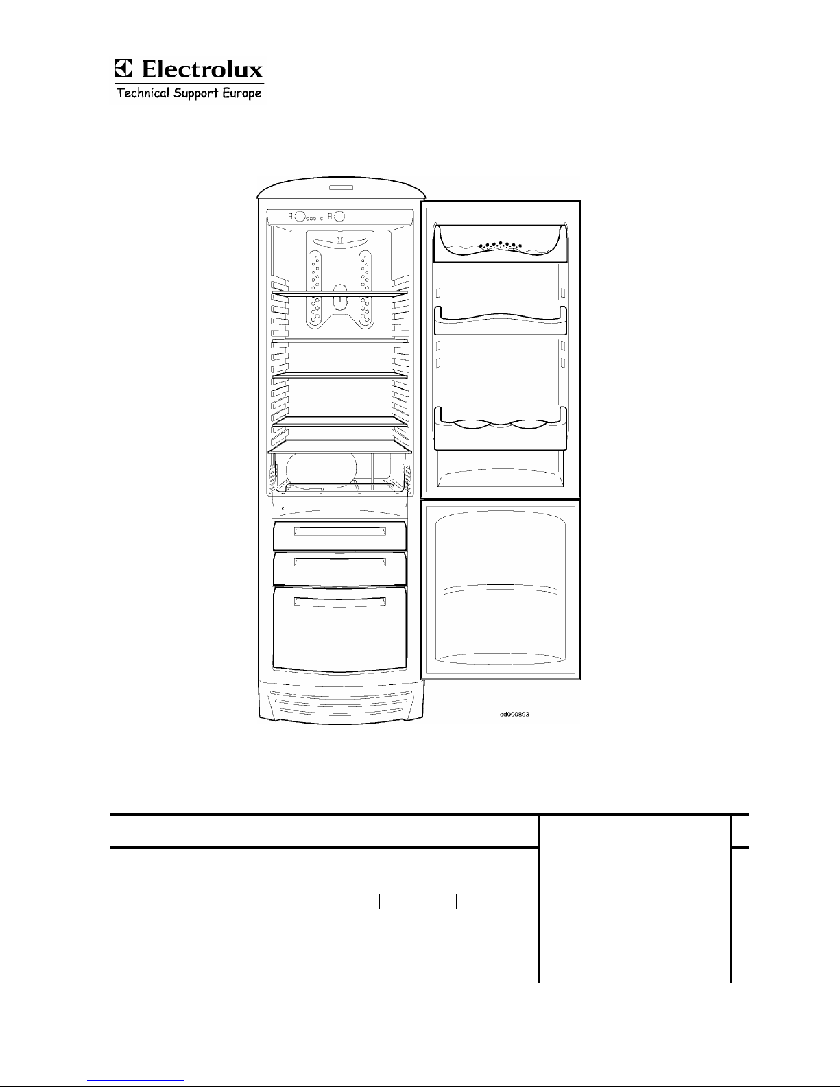
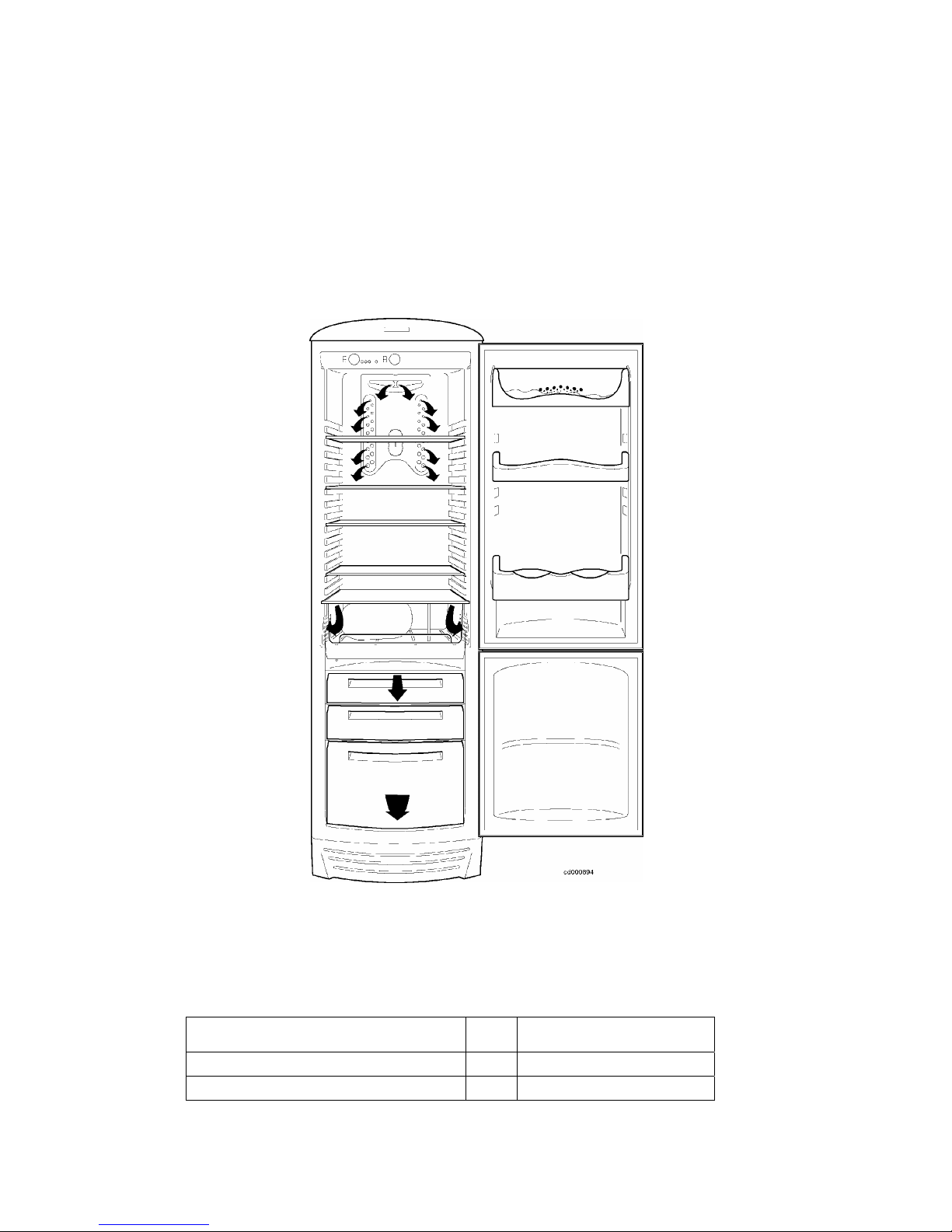
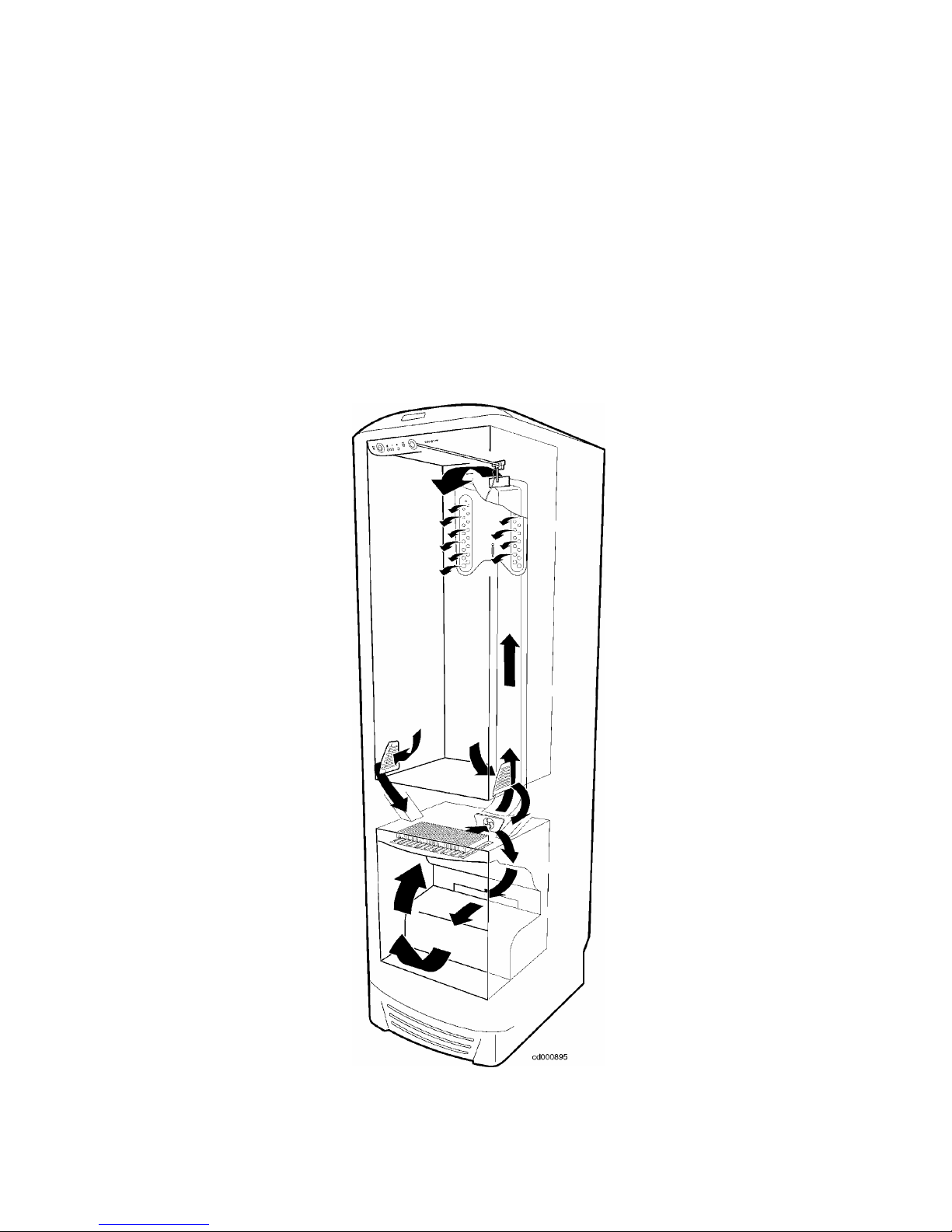
1.2. EUROFLEC: total nofrost
The EUROFLEC is a total no-frost appliance, and as such its operation is based exclusively on the battery
evaporator in the freezer compartment, which cools the air; the fan circulates the air.
A duct embedded in foam channels the cold air into the refrigerator compartment, where the flap-operated
mechanical thermostat regulates the flow of cold air and thus the temperature inside the refrigerator
compartment. The air returns to the freezer compartment through two outlets located at each side of the
vegetable drawer.
Operation of the compressor (switching on and off) is controlled by an NTC sensor located externally (in air)
in the freezer compartment. The electronic system periodically defrosts the ice which accumulates on the
evaporator battery; defrosting terminates when a second NTC sensor, positioned in contact with the
evaporator battery, detects a temperature of +15°C.
The main characteristic of the control system used in the EUROFLEC is the fact that the defrost operating
cycles are not of fixed duration, but calculated on the basis of the time required for defrosting (see chapter
5).
EUROFLEC 7/36
2. Characteristics
2.1. Dimensions and volumes
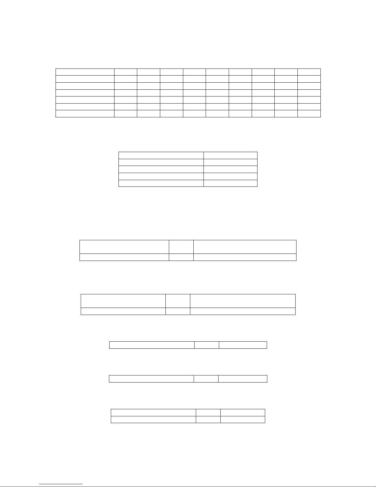
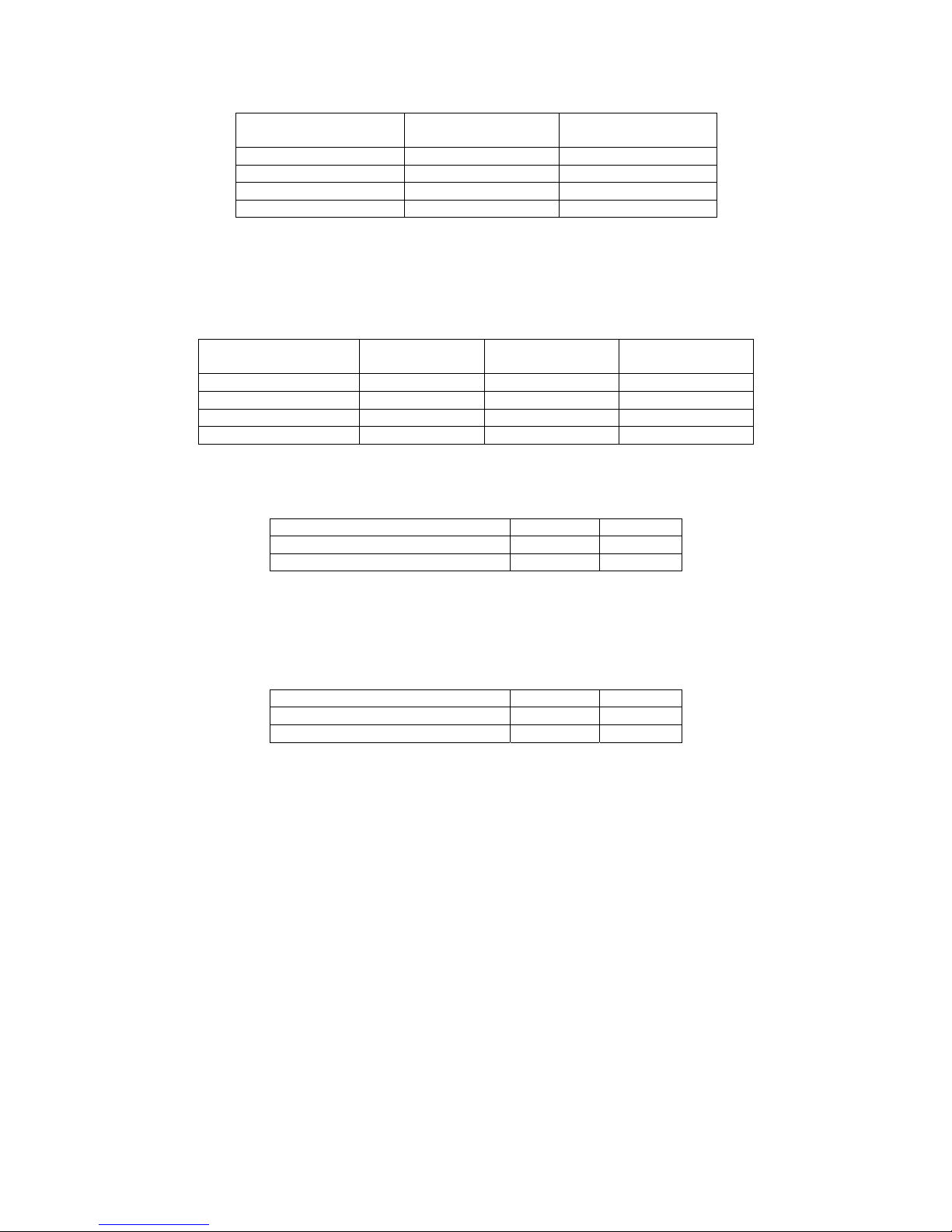
The EUROFLEC models are numbered from 1 to 9 (n° 7 has been eliminated):
Model no. 1 2 3 4 5 6 8 9
Height mm 1950 1800 1800 1800 1650 1650 1750 1950
Width mm 600 600 600 600 600 600 600 600
Depth mm 595 595 595 595 595 595 595 595
Gross vol. freezer litres 94 126 94 157 94 126 94 126
Gross vol. fridge litres 267 193 230 156 193 155 217 230
Total gross vol. litres 361 319 324 313 287 281 311 336
2.2. Technical characteristics
Performance:
Refrigerator
from 1°C to 10°C
Freezer
4 stars
Energy class
B
Climate class
SN , N , ST
Coolant
R600a
Compressor:
See the specific spare parts list for each model!
Evaporator fan:
Voltage
(direct current)
V 18
Power W 3
Condenser fan:
Voltage
(direct current)
V 18
Power W 2.5
Defrosting heater:
Power at 230V W 250
Drainage duct heater:
Power at 230V W 43.5
Safety overheating switches:
Opening °C 55
Closure °C 45
EUROFLEC 8/36
Settings for refrigerator compartment:
Position of
thermostat knob
Cut-in Cut-out
stand by* +16°C +13°C
3 +10°C +7°C
5 +7°C +4°C
7 +4°C +1°C
* In this position, the thermostat does NOT completely blocks the passage of cold air coming from the freezer
compartment.
Settings for freezer compartment:
Position of
thermostat knob
Cut-in Cut-out Alarm
0 -15°C -16°C -12°C
3 -18°C -19°C -12°C
5 -21°C -22°C -12°C
7 -23°C -24°C -12°C
Normal operating times:
Pre-determined** Hours 6
Minimum Hours 4
Maximum Hours 25
** A six-hour operating cycle is performed each time the appliance is switched on.
Defrosting:
Standard time Minutes 22
Maximum time Minutes 30
Temp. for end of defrosting °C +15
EUROFLEC 9/36
3. Diagrams
3.1 Functional diagram
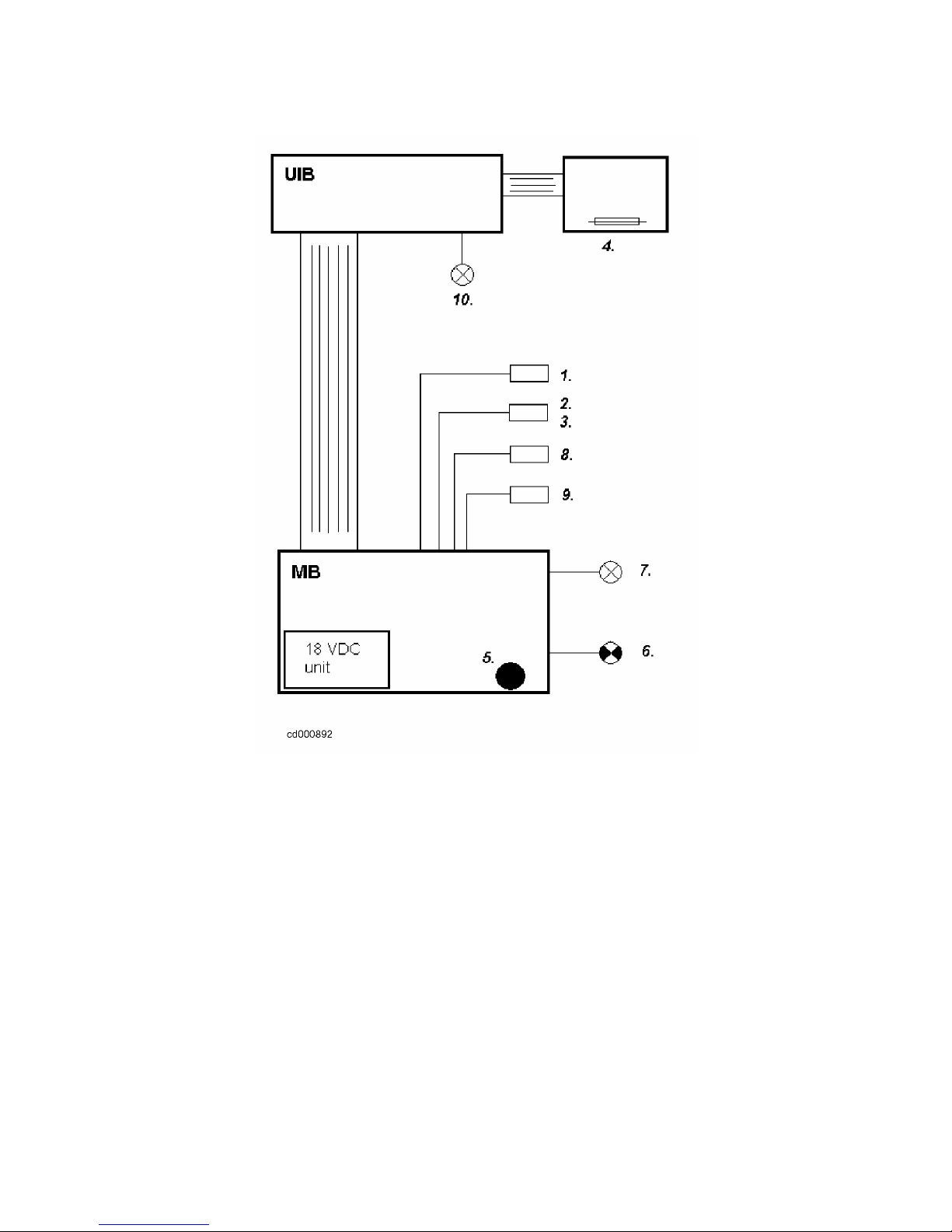
The control system of the EUROFLEC consists of a UIB user interface board and a MB control and power
board with the following inputs and outputs:
INPUTS:
1. Freezer door switch;
2. NTC sensor on evaporator;
3. NTC sensor in air;
4. Refrigerator door switch (reed element with foam-embedded magnet in door);
OUTPUTS:
5. buzzer;
6. compressor;
7. condenser fan;
8. evaporator fan;
9. defrosting heaters;
10. refrigerator compartment light;
EUROFLEC 10/36

EUROFLEC 11/36
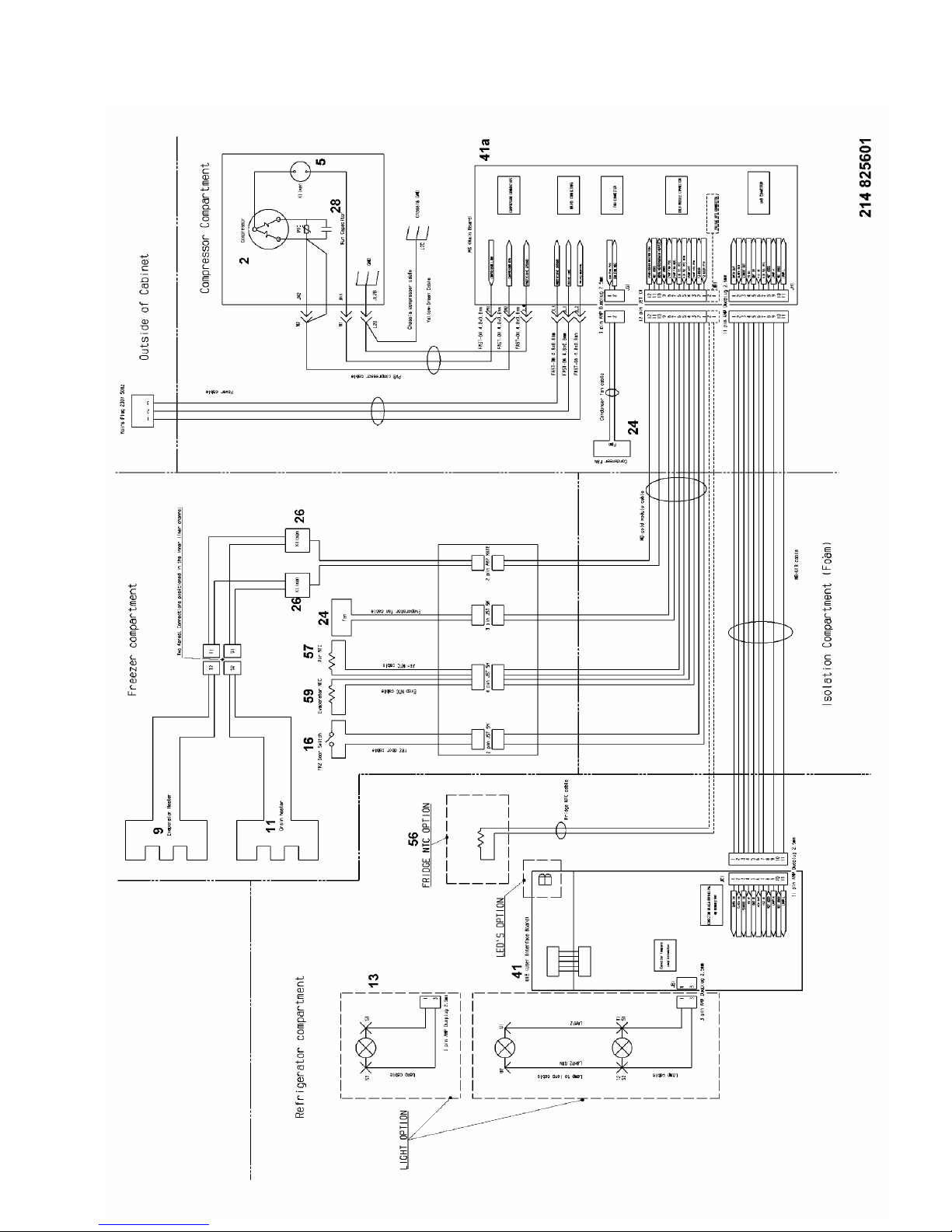
Legend:
2. compressor;
5. overload cut-out;
9. evaporator defrosting heater;
11. drainage duct defrosting heater;
13. refrigerator compartment light;
16. freezer door switch;
24. evaporator/condenser fan;
26. safety thermal switch;
28. running condenser;
41. display board (UIB);
41a. control and power board (MB);
56. NTC sensor refrigerator (optional);
57. NTC sensor freezer in air;
59. NTC sensor freezer evaporator;
 Loading...