

Electrolux Eurocombi Service Manual
SERVICE MANUAL
REFRIGERATION
© ELECTROLUX ZANUSSI Publication number
ELETTRODOMESTICI S.p.A. 599 34 04-61
VIA GIARDINI CATTANEO, 3 2001-01-15
I - 33170 PORDENONE (ITALY) EN/SERVICE/AA
Fax (0434) 394096
EUROCOMBI
This publication updates and replaces the previous.

Eurocombi
2/32

Eurocombi
3/32
CONTENTS
1. Introduction
1.1 Presentation page 5/33
1.2 Eurocombi: total nofrost page 7/33
2 Characteristics
2.1 Dimensions and volumes page 8/33
2.2 Characteristics page 8/33
2.3 Circuit diagram page 10/33
3 Components
3.1. Main components page 11/33
3.2. Electronic module page 13/33
3.2.1. CTB – Control board page 14/33
3.2.2. PWB – Power board page 14/33
3.2.3. Connection box page 14/33
3.3. Fans page 15/33
3.3.1. Operation with doors closed page 15/33
3.3.2. Door aperture with compressor on page 16/33
3.3.3. Door aperture with compressor off page 16/33
3.4. Heating elements page 17/33
3.5. NTC sensors page 17/33
3.6. Overheating protection page 17/33
3.7. Evaporator page 18/33
3.8. Condenser page 18/33
3.9. Flap-operated mechanical thermostat page 18/33
4. Operation
4.1. Normal operation page 19/33
4.2. Defrosting page 19/33
5. Control panel
5.1. Switching the appliance on and off page 20/33
5.2. “Door open” alarm page 21/33
5.3. “Temperature” alarm page 21/33
5.4. Rapid freezing page 21/33
5.5. NTC sensors failure page 22/33
6. Service mode
6.1. Activation page 23/33
6.2. Signalling of faults page 23/33
6.3. Separate activation of loads page 24/33
6.4. Checking the door switches page 24/33
6.5. Disactivation page 24/33
6.6 Days counter page 24/33
7. Demo mode
7.1. Selecting Demo mode page 25/33
7.2. Main functions page 25/33
7.3. Exiting Demo mode page 25/33
8. Accessibility
8.1. Flap-operated thermostat page 26/33
8.2. Control board (CTB) page 28/33
8.3. Freezer compartment page 29/33
8.4. Glass shelves page 32/33
8.5. Air inlets page 32/33
8.6. Power board (PWB) page 33/33

Eurocombi
4/32

Eurocombi
5/32
1. INTRODUCTION
1.1. Presentation
The EUROCOMBI is a new free-standing combined refrigerator (with a refrigerator compartment in the upper
section and the freezer in the lower section) produced in the Fuenmayor factory in Spain.
This appliance features a single compressor and a total no-frost system. The operating cycles are controlled
electronically. The temperature inside the refrigerator compartment is controlled by a flap-operated
mechanical thermostat.
The Eurocombi range consists of eight models, with ALFA or DELTA stylings. All models are arched doors.
The differences between the various models consist in the size of the refrigerator and freezer compartments
and therefore in the number of shelves and drawers.
Eurocombi
6/32
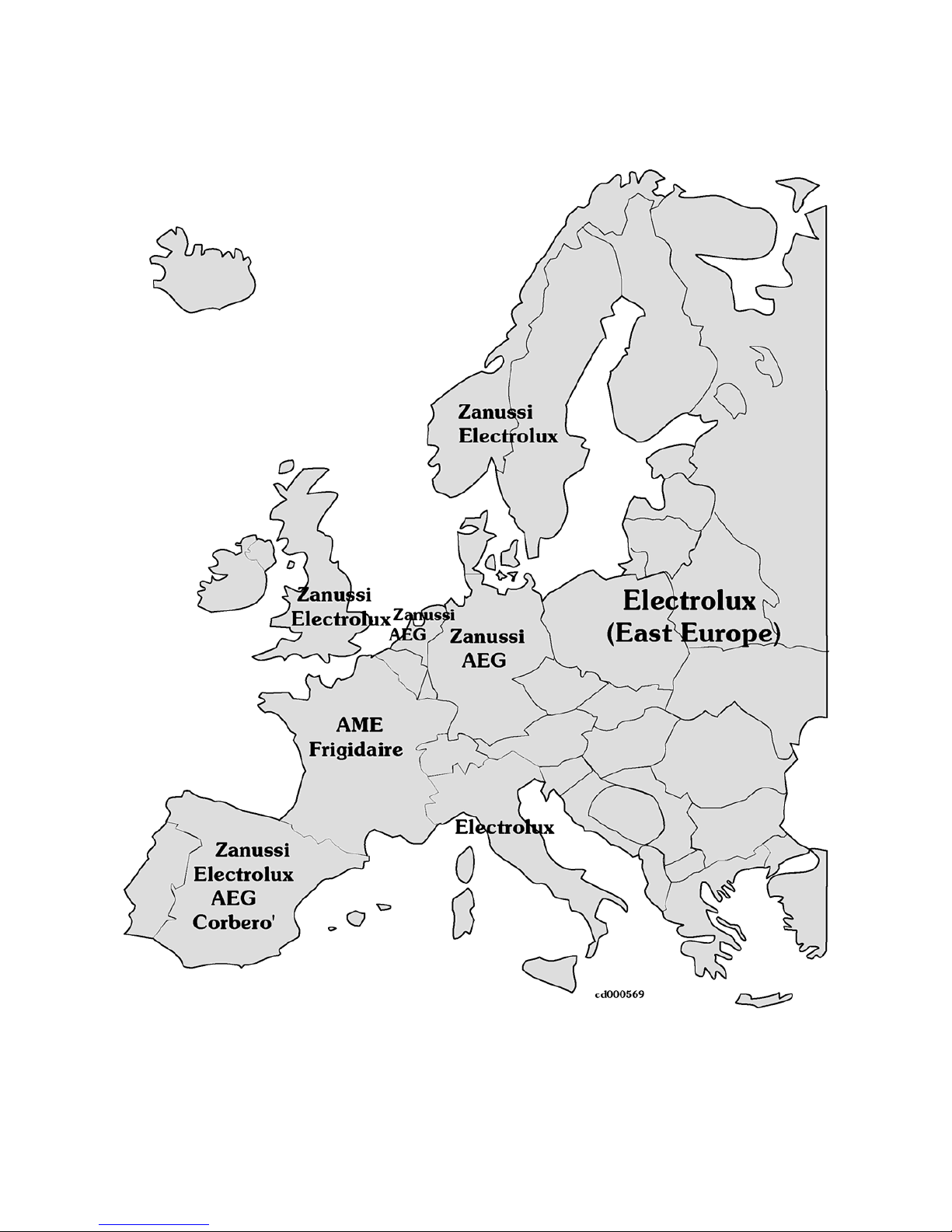
Markets: UK, Spain, France, Germany, Italy, Sweden, Norway, Finland, Est Europe.
Brands: Zanussi, Electrolux, AEG, AME, Frigidaire, Corbero’.
Eurocombi
7/32
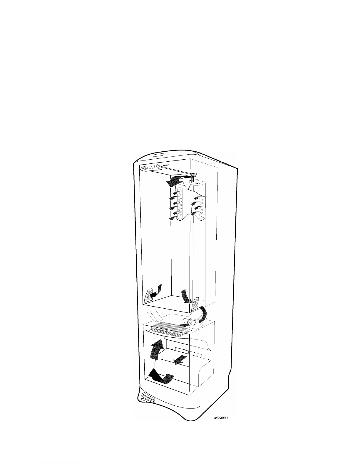
1.2. Eurocombi: total no-frost
The Eurocombi is a total no-frost appliance, and as such its operation is based exclusively on the battery
evaporator in the freezer compartment, which cools the air; the air is circulated by the fan.
A duct embedded in foam channels the cold air into the refrigerator compartment, where the flap-operated
mechanical thermostat regulates the flow of cold air and thus the temperature inside the refrigerator
compartment. The air returns to the freezer compartment through two outlets located at each side of the
vegetable drawer.
Operation of the compressor (switching on and off) is governed by an NTC sensor located externally (in air)
in the freezer compartment. The electronic system periodically defrosts the ice which accumulates on the
evaporator battery; defrosting terminates when a second NTC sensor, positioned in contact with the
evaporator battery, detects a temperature of +15°C.
The main characteristic of the control system used in the Eurocombi is the fact that the defrost operating
cycles are not of fixed duration, but calculated on the basis of the time required for defrosting (see section 4,
page 16).
Eurocombi
8/32
2. CHARACTERISTICS
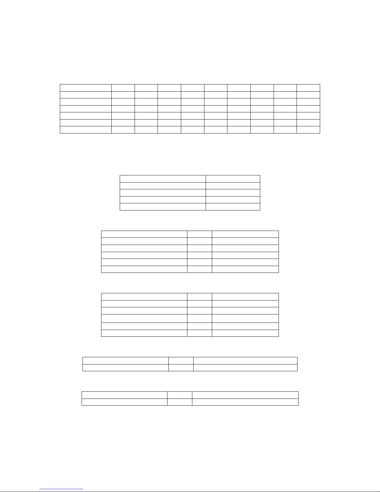
2.1. Dimensions and volumes
The models in the Eurocombi range are numbered from 1 to 9 (with the exception of number 7, which has
been eliminated).
Model no. 1 2 3 4 5 6 8 9
height* mm 1950 1800 1800 1800 1650 1650 1750 1950
width mm 595 595 595 595 595 595 595 595
depth mm 664 664 664 664 664 664 664 664
gross vol. freezer liters 94 126 94 157 94 126 94 126
gross vol. fridge liters 267 193 230 156 193 155 217 230
total gross vol liters 361 319 324 313 287 281 311 336
*with top panel: +60mm
2.2. Technical characteristics
Performance:
Refrigerator
from 1°C to 10 °C
Freezer
4 stars
Energy class
C
Cilmate class
SN, N, T,ST
Coolant
R600a
Compressor: HPT12 high efficiency (N, SN class)
Power supply V/Hz 220-240/ 50
Rated power HP 1/5
Power absorption W 135
Current (normal / starting) A 0.6/8
Output power kcal/h 141
Resistance (normal / starting) ohm 17.8/27
Compressor: HPT14 high efficiency (T, ST class)
Power supply V/Hz 220-240/ 50
Rated power HP 1/5
Power absorption W 143
Current (normal / starting) A 1.1/6.4
Output power kcal/h 162
Resistance (normal / starting) ohm 11.6/19
Evaporator fan:
Voltage (DC) V 21 (class N) , 24 (class T)
Power W 3
Condenser fan:
Voltage (DC) V 21 (class N) , 24 (class T)
Power W 2.5

Eurocombi
9/32
Defrosting heater:
Power at 230V W 250
Drainage duct heater:
Power at 230V W 43.5
Safety overheating switches:
aperture °C 55
closure °C 45
Settings for refrigerator compartment:
Position of
thermostat knob
Cut-in Cut-out
stand by* Flap closed Flap closed
3 +10 °C +7°C
5 +7°C +4°C
7 +4°C +1°C
* in this position, the thermostat completely blocks the passage of cold air coming from the freezer
compartment.
Settings for freezer compartment:
Position of
thermostat knob
Cut-in Cut-out Alarm
0 -15 °C -16°C -12°C
3 -18 °C -19°C -12°C
5 -21°C -22°C -12°C
7 -23°C -24°C -12°C
Normal operating times:
pre-determined** hrs 6
minimum hrs 4
maximum hrs 25
** A six-hour operating cycle is performed each time the appliance is switched on.
Defrosting:
standard time minutes 22
maximum time minutes 30
temp. for end of defrosting °C +15
Eurocombi
10/32
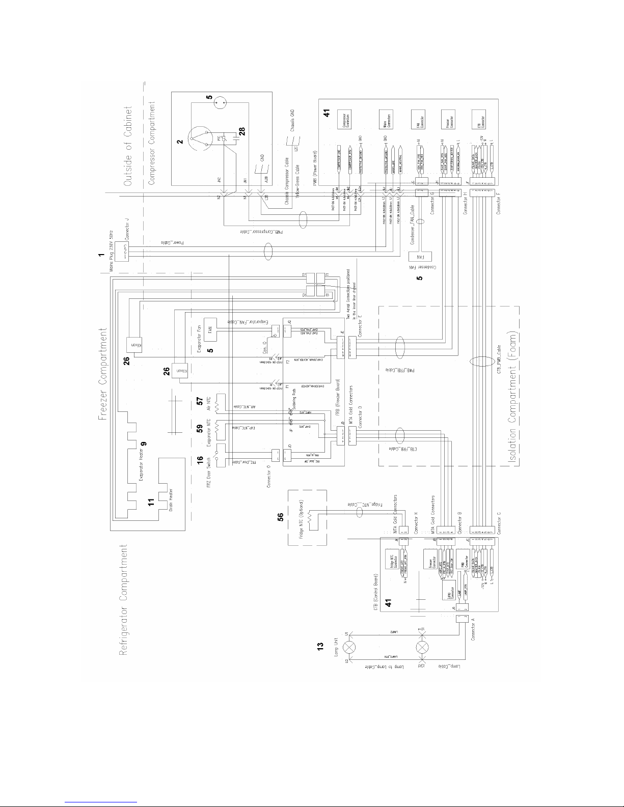
2.3. Circuit diagram
1 power supply; 2 compressor; 5 fan; 9 defrosting heater; 11 drainage duct heater; 13 refrigerator light; 16
freezer switch; 26 safety switch (+55°C); 28 condenser; 41 electronic circuit board; 56 air sensor for
refrigerator (optional); 57 external (in air) NTC sensor; 59 NTC sensor for evaporator.
 Loading...