

Electrolux AND42391X, END42391W, S75428DT, RND42391W, RND42391S Service Manual
...
- ITZAA 1/31 599 38 97-89
SERVICE MANUAL
REFRIGERATION
© Electrolux Home Products S.p.A.
Spares Operations Italy
Corso lino Zanussi, 30
I - 33080 Porcia (PN)
Fax +39 0434 394096
S.O.I.
Edition: 06.2007
Publication no.
599 38 97-89
EN
REFRIGERATORS
COMBI TOP NO FROST
PARTIAL with ERF550
electronic
FACTORY: ZS

- ITZAA 2/31 599 38 97-89
CONTENT
1 INTRODUCTION ....................................................................................................................................... 3
2 AIR CIRCULATION.................................................................................................................................... 6
3 REFRIGERATION CIRCUIT.................... .... ............................................. ... .............................................. 7
4 ELECTRIC WIRING................................................................................................................................... 8
5 COMPONENTS....................................................................................................................................... 10
5.1 Controls on air box...................... ... ... .... ... ... ... ... .... ... ... ... .... ... ........................................................... 10
5.2 Electronic board............................. ... .... ... ... ... ... .... ............................................. ... ........................... 10
5.2.1 Power and display board ERF550.......................................................................................... 11
5.3 Cooler compartment........................................................................................................................ 13
5.3.1 Temperature sensor ............................................................................................................... 14
5.3.2 Air box..................................................................................................................................... 14
5.3.2.1 Air box fan .................................................................................................................... 15
5.3.2.2 Cooler door switch........................................................................................................ 15
5.4 Freezer compartment ...................................................................................................................... 16
5.4.1 Cold module fan...................................................................................................................... 17
5.4.2 Defrosting heater.................................................................................................................... 17
5.4.3 Thermal switches.................................................................................................................... 17
5.5 Compressor compartment ............................................................................................................... 18
5.5.1 Connector box ........................................................................................................................ 18
6 MAIN FUNCTIONS.................................................................................................................................. 19
6.1 Normal............................................................................................................................................. 19
6.2 Normal with first switching on or power failure .................. ... ... ............................................. ... .... .... 19
6.3 Defrosting ........................................................................................................................................ 20
6.4 Flow chart for the defrosting management ...................................................................................... 22
6.5 Malfunctioning of cooler air temperature sensor.............................................................................. 23
7 ACCESSIBILITY...................................................................................................................................... 24
7.1 Freezer compartment ...................................................................................................................... 24
7.1.1 Battery evaporator.................................................................................................................. 24
7.1.1.1 Replacement of the thermal switches........................................................................... 25
7.2 Air box.............................................................................................................................................. 27
7.3 Compressor compartment ............................................................................................................... 28
8 TROUBLESHOOTING............................................................................................................................. 29
8.1 Water leakage inside the freezer compartment....... ... ... .................................................................. 29
8.2 Failed defrosting: ............................................................................................................................. 29
9 SPECIAL FUNCTIONS............................................................................................................................ 30
9.1 Manual defrosting ....... ... ... ... .... ... ... ... .... ............................................. ... ... ........................................ 30
10 DISPLAY SYMBOLS ............................................................................................................................... 31
- ITZAA 3/31 599 38 97-89
1 INTRODUCTION
This manual describes the 70 cm wide Combi Top PARTIAL NO FROST refrigerators with ERF550 electronic
produced in the Susegana factory called ZS.
These models feature:
- partial No Frost (no frost freezer, static refrigerator)
- free standing
- single-compressor
- electronic control (electronic board ERF550)
- air box fan in the cooler compartment
They are appliances (RI3406WL and RI3406W) with the following PNCs:
PNC MODEL BRAND
925589500 END42391W Electrolux
925589501 END42391X Electrolux
925589502 AND42391W Electrolux Arthur Martin
925589503 AND42391X Electrolux Arthur Martin
925589504 END42391X Electrolux
925589505 S75428DT AEG-Electrolux
925589507 RND42391W Rex-Electrolux
925589508 RND42391S Rex-Electrolux
925589509 RND42351X Rex-Electrolux
925589510 S75428DT1 AEG-Electrolux
925589511 PD431NFX Zoppas
925589512 S75428DT2 AEG-Electrolux
925589513 END42391S Electrolux
925587500 END32321W Electrolux
925587501 END32321X Electrolux
925587502 AND32321W Electrolux Arthur Martin
925587503 END32321X Electrolux
925587504 AND32321S Electrolux Arthur Martin
925587505 S75320DT AEG-Electrolux
925587506 S75328DT AEG-Electrolux
925587507 RND32351M Rex-Electrolux
925587508 RND32351Z Rex-Electrolux
925587509 RND32351Y Rex-Electrolux
925587510 S75328DT1 AEG-Electrolux
925587511 S75328DT2 AEG-Electrolux

- ITZAA 4/31 599 38 97-89
The controls of the appliance are inserted into the air box positioned in the cooler compartment.
The power and control board is of ERF550 type.
The appliance is switched on and off by simply connecting and disconnecting the plug.
The appliance features only one compressor and it is not possible to switch off only one of the two compart-
ments.
The temperatures regulation is the following:
• from +8 to +2 °C for the cooler
The temperature of the fridge compartment is displayed through the ligh ting up of the LEDs of the electronic
PCB.
The appliance has the following functions:
• Forced ventilation cooler compartment
PNC MODEL BRAND
925587512 END32321S Electrolux
925587513 END32321W Electrolux
925587522 RND32351M Rex-Electrolux
925587523 RND32351Z Rex-Electrolux
925587524 RND32351Y Rex-Electrolux
- ITZAA 5/31 599 38 97-89
The cooler compartment is provided with a manually actioned fan (ON/OFF button) inserted in the air box.
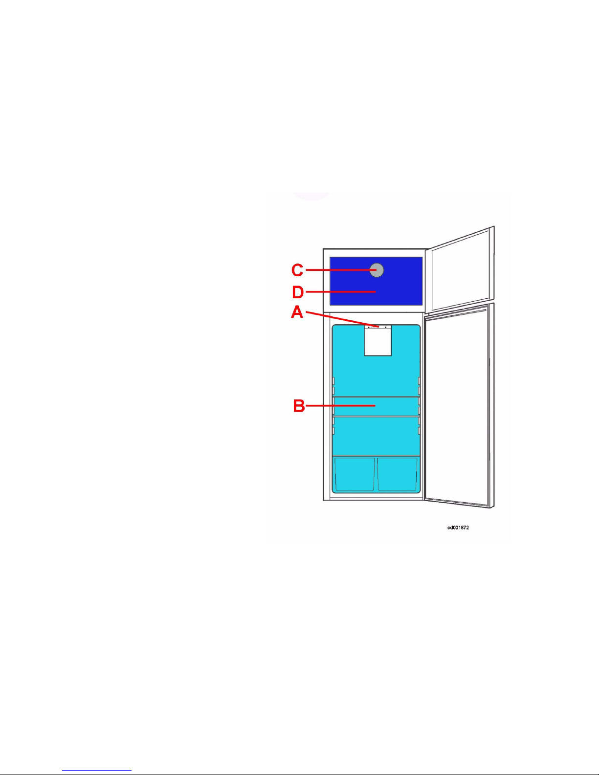
The appliance consists of the following compartments:
• freezer;
•cooler;
The evaporating circuit consists of:
• cold module (freezer compartment);
• tube evaporator (cooler compa rtment).
Key:
A. control panel on the air box
B. cooler compartment
C. cold module
D. freezer compartment (freezer No Frost)
- ITZAA 6/31 599 38 97-89
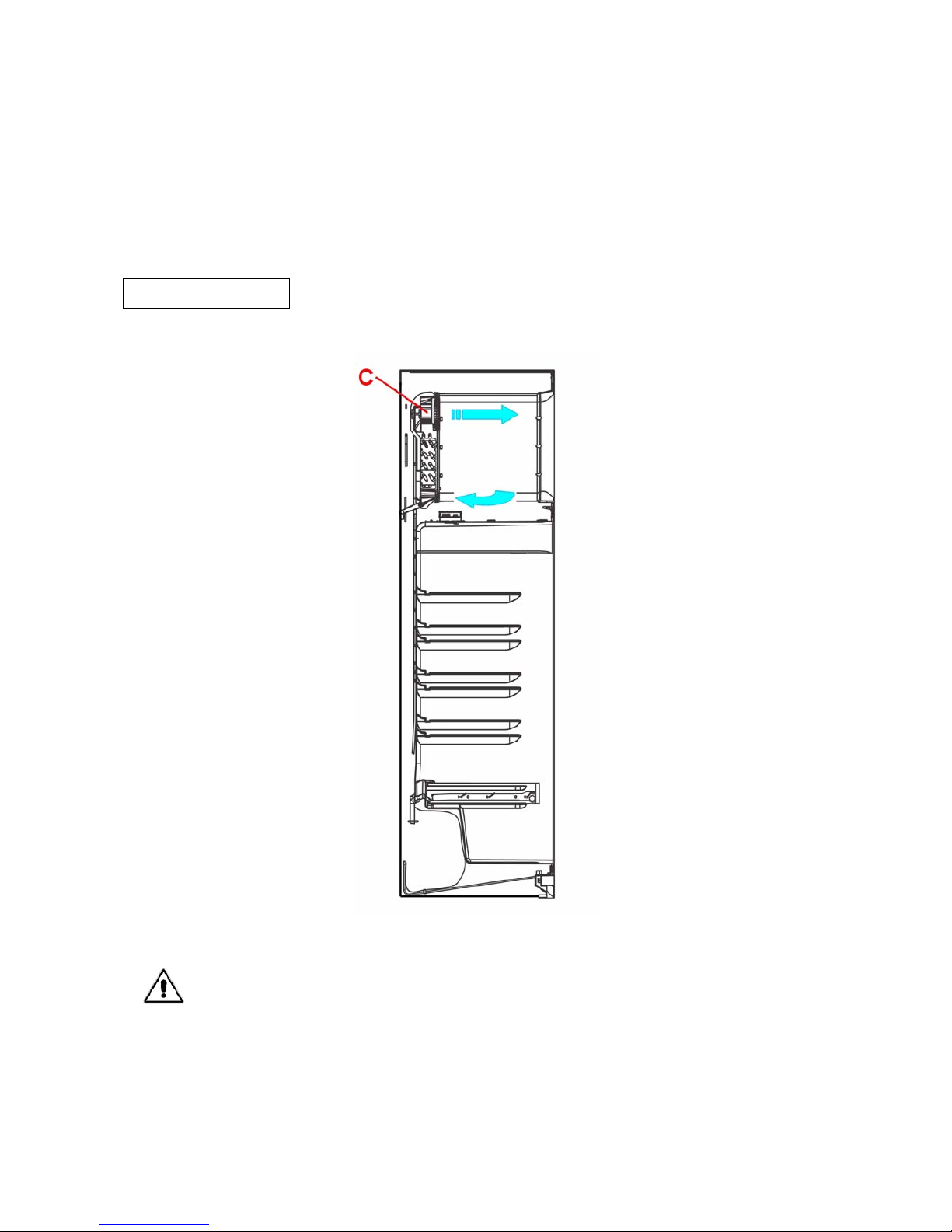
2 AIR CIRCULATION
Unlike the NO FROST refrigerators, in the PARTIAL NO FROST type the cooler and freezer compartments are
separated physically.
The battery evaporator cools only the freezer compartment, while the tube evaporator cools only the cooler
compartment.
The cold produced by the battery evaporator in the freezer compartment is distributed by the fan C placed
above the cold module.
AIR FLOW
In case of freezer door opening, the cold module fan does not stop.
- ITZAA 7/31 599 38 97-89
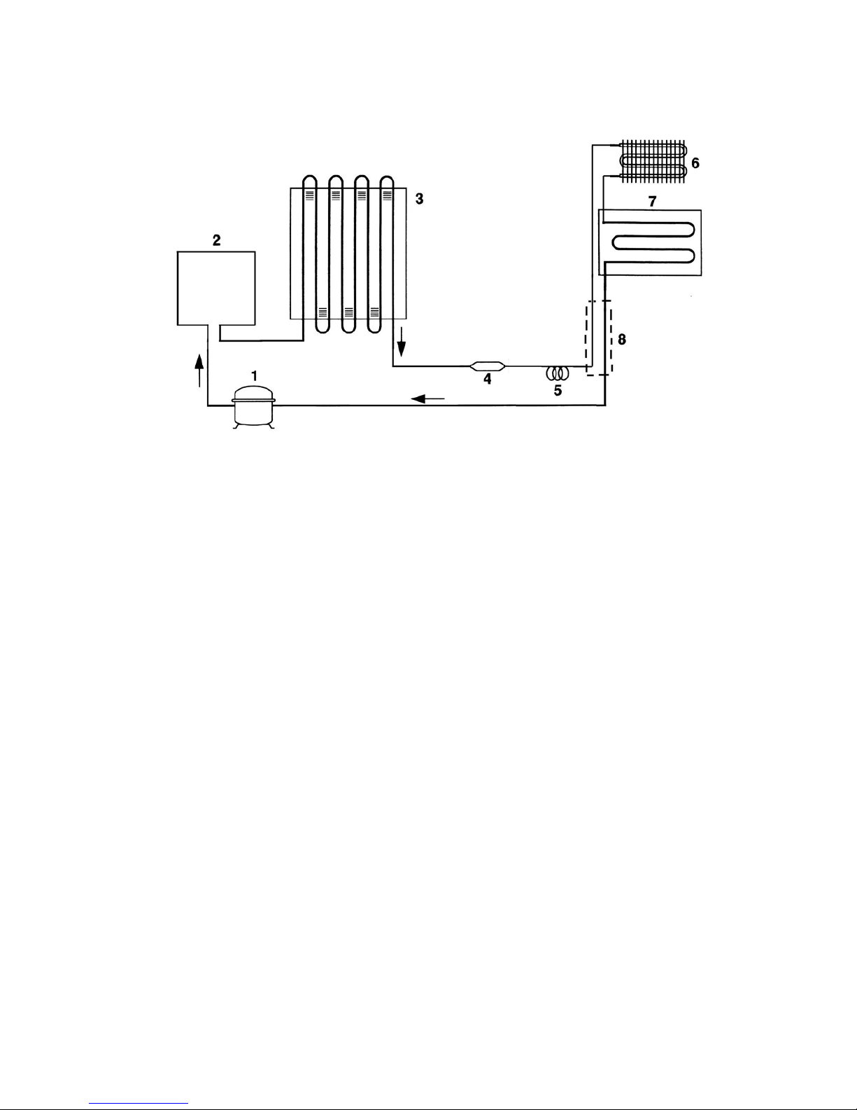
3 REFRIGERATION CIRCUIT
Key:
1. compressor;
2. anti-condensation coil;
3. condenser;
4. dehydrator filter;
5. capillary;
6. battery evaporator (freezer compartment);
7. tube evaporator (cooler compartment).
8. exchanger.
- ITZAA 8/31 599 38 97-89
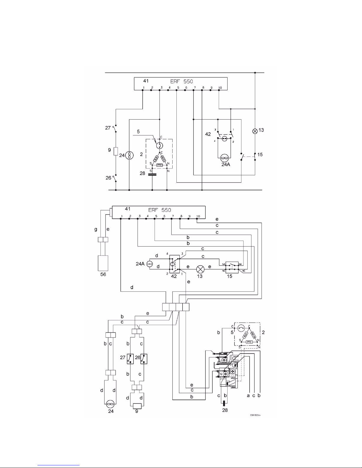
4 ELECTRIC WIRING
(Check the specific diagram for each model!)

- ITZAA 9/31 599 38 97-89
Key:
COMP compressor
FAN fan
HEATER defrosting heater
D.T.S. defrosting cut-out switch (+8 °C)
S.T.S. safety thermal switch (+40 °C)
ON on
OFF off
CLOSED closed
OPENED opened
A start of defrosting procedure
B activation of defrosting heater
C defrosting cut-out switch
D end of defrosting procedure
a. yellow-green
b. brown
c. blue
d. white
e. black
f. grey
g. red
- ITZAA 10/31 599 38 97-89
5 COMPONENTS
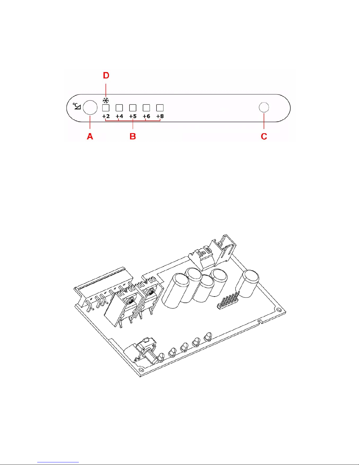
5.1 Controls on air box
Key:
A. temperature selection button
B. LED bar display
C. cooler door button
D. ACTION FREEZE symbol
5.2 Electronic board
The electronic board of the appliance consists of:
1. power and display board ERF550
 Loading...