

Page 1

ENGLISH
GB CONTENTS
A GENERAL RECOMMENDATIONS.......................................................... Page 4
A1 HANDLING......................................................................................................................Page 4
A2 UNPACKING....................................................................................................................Page 4
A3 DISPOSAL.......................................................................................................................Page 4
A4 TECHNICAL DATA ..........................................................................................................Page 5
B INSTRUCTIONS FOR THE INSTALLER/MAINTENANCE PERSON..... Page 7
B1 WATER CONNECTION...................................................................................................Page 7
B2 ELECTRICAL CONNECTION .........................................................................................Page 7
B3 WARNING MESSAGES DISPLAYED ON THE CONTROL PANEL................................Page 8
B4 DETERGENT/RINSE-AID DISPENSERS AND SETTINGS............................................Page 9
B5 SETTING THE DISPENSERS.........................................................................................Page 10
B6 MAINTENANCE...............................................................................................................Page12
C INSTRUCTIONS FOR THE USER........................................................... Page 13
C1 STARTING.......................................................................................................................Page 14
C2 WASH CYCLES...............................................................................................................Page14
C3 OPERATION....................................................................................................................Page 14
C4 END OF WORK AND DAILY CLEANING.......... ... ... .... ... ... ... .... ... ... ... ... .... ... ... ... .... ... .......Page 15
C5 WARNING MESSAGES DISPLAYED ON THE CONTROL PANEL................................Page 16
C6 RESIDUAL RISKS...........................................................................................................Page 16
D TROUBLESHOOTING............................................................................. Page 18
3
Page 2
WARNING
A GENERAL RECOMMENDATIONS
PE
PP
PS
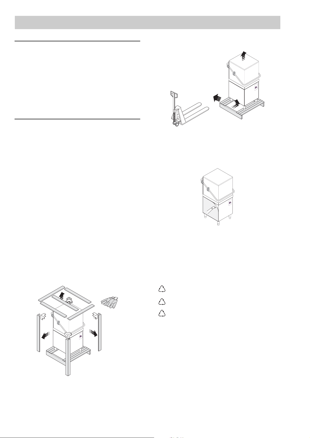
Lift the appliance using a lift truck, remove the base
CAREFULLY READ THE INSTALLATION, OPERATING AND MAINTENANCE INSTRUCTIONS BEFORE
INSTALLING THIS APPLIANCE. INCORRECT
INSTALLATIONS, ADAPTATIONS OR ALTERATIONS COULD CAUSE DAMAGE TO PROPERTY
OR INJURY TO PERSONS. MALICIOUS DAMAGE,
DAMAGE DUE TO NEGLIGENCE, OR TO FAILURE
TO COMPLY WITH INS TRUCTIONS AND REGULATIONS, OR TO INCORRECT CONNECTIONS OR
UNAUTHORISED TAMPERING INVALIDATE ANY
WARRANTY AND RELIEVE THE MANUFACTURER
OF ALL LIABILITY.
and position the appliance where it is to be installed.
1. Carefully read this instructions booklet, as it contains important advice for safe installation, operation and maintenance.
Keep this booklet to hand in a safe place for future
reference by other operators.
2. Installation should be carried out by qualified
engineers, in accordance with current regulations and with the manufacturerís instructions.
3. The appliance should only be used by persons specifically trained in this operation.
4. Switch off the appliance in the event of failure or
malfunctioning.
Only have the appliance repaired by a service centre
authorised by the manufacturer and ask for original
spare parts.
A1 HANDLING
Use suitable means to move the appliance: a lift truck
or fork pallet trucks (the forks should reach more than
halfway beneath the appliance).
A2 UNPACKING
Wear protective gloves to unpack.
Figure 2
Remove the protective film and ensure that the packaging material is disposed of correctly in compliance
with the regulations in force in the country wh ere the
product is to be used.
Figure 3
A3 DISPOSAL
All the packaging materials are environment friendly.
They may be kept without danger, recycled or burned
in a special waste incineration plant. Recyclable plastic
components are marked as follows:
4
polyethylene external wrapping film,
instruction bag.
polypropylene top packaging panels,
straps.
polystyrene foam protective
surround elements.
Wood and cardboard components may be disposed of
according to local regulations in force. Appliances that
have reached the end of their service life should be suitably disposed of. The appliance should be dismantled
according to regulations in force. All metal parts are in
stainless steel (AISI 304) and are removable. Plastic
parts are marked with the symbol of the material.
Figure 1
Page 3
ENGLISH
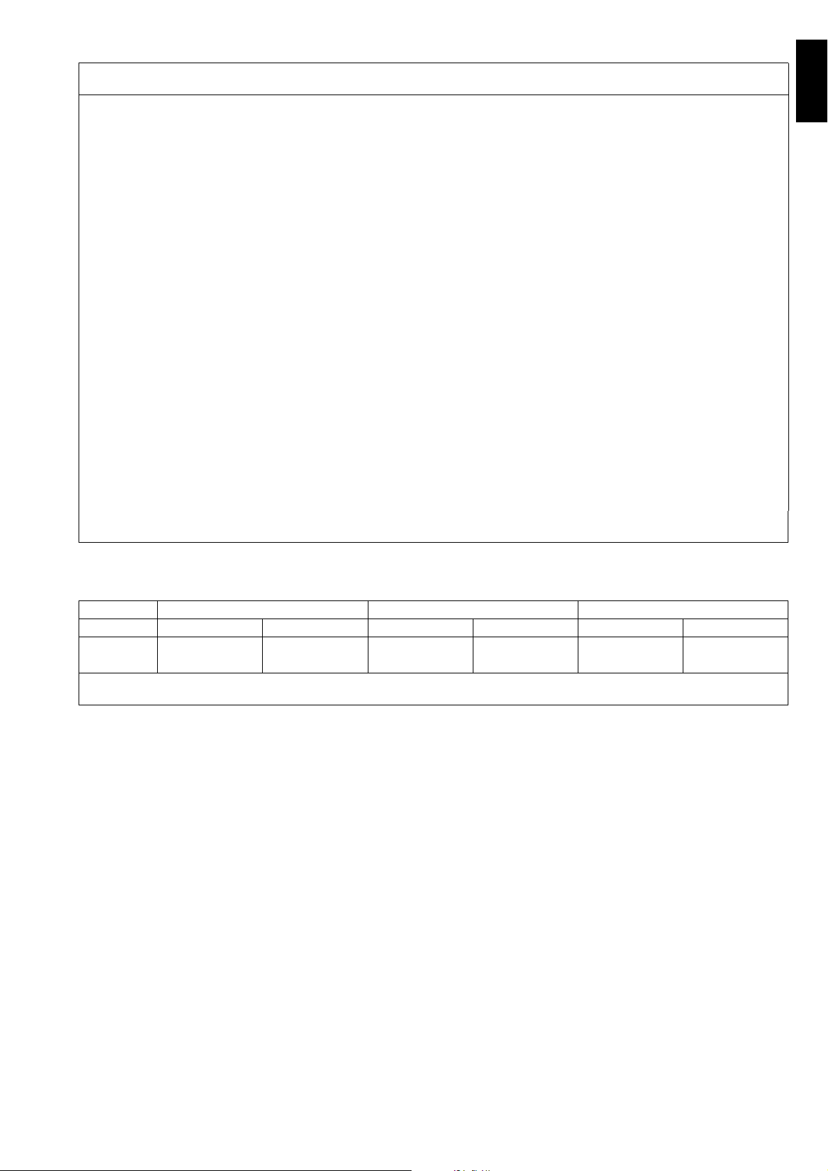
A4 TECHNICAL DATA
MODEL EHTAROW / ZHTAROW /
OHTAROW
Supply voltage:
• three-phase version V 400...415- 3N~ 220...240- 3~ N~
- convertible to V 220...240- 3~ 400...415- 3
- convertible to V 220...240- 1N~ (**) 220...240- 1N~ (**)
Frequency Hz 50 60
Max. power input (three-phase version) kW 15,9 15,9
Max. power input (single-phase version) kW 9,9 9,9
Boiler heating elements kW 6,0 + 6,0 (**) 6,0 + 6,0 (**)
Tank heating elements kW 3,0 3,0
Water supply pressure kPa [bar] 50...700 [0,5...7] 50...700 [0,5...7]
Water supply temperature °C 10 ... 60 10 ... 60
Water supply hardness °fH [°dH ] 14 [8] max 14 [8] max
Rinse cycle water consumption l 3,0 3,0
Boiler capacity l 12 12
Tank capacity l 42 42
Standard cycle time:
- Thermal label mode sec. 77-90-150 77-90-150
- High productivity mode sec. 54-90-150 54-90-150
Legal noise level dB(A) <68 <68
Protection rating IPX4 IPX4
Net weight kg 98 98
Power supply cable H07RN-F H07RN-F
Supply cord diameter (min - max value) mm 18-25 18-25
EHTAROW60 / ZHTAROW60 /
OHTAROW60
(**) = Reduce the power of the boiler from 12 kW to 6kW as shown in the circuit diagram.
Table 1
400..415 V 3N 220...240 V 3 220…240 V 1N
CSCSCS
9,9 kW - - - - 3X10 60 A 1P+N
15,9 kW 5X6 40 A 3P+N 4X10 60 A 3P - -
C = Power supply cable
S = On/Off switch
Table 2
Standard cycle time may vary should the inlet water temperature be differen t from that indicated above.
5
Page 4
1515
636
748
55
236
543
55
327
215
132
39
833
126
329
329
329
138
65
658
833
410
1970
152
56
404
559
167
200
875
140
S2
650
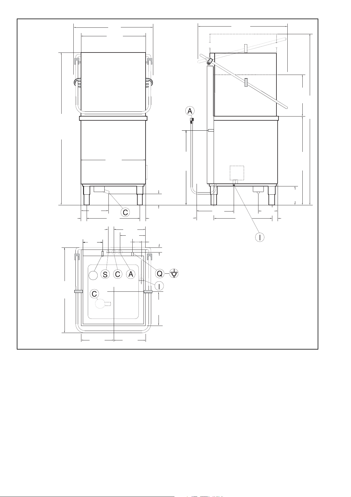
Figure 4
Legend Figure 4
A - Water inlet pipe with Ø 3/4” G fittings
C - Outlet pipe Øi 40 mm (^) – Øi 18 mm (*).
I - Power supply
S - Pipe inlet for detergents
S2 - Solid detergent injector (only ”OHTAROW / OHTAROW60” vers ions)
Q - Unipotential screw
(^) - Only for model with free-fall drainage
(*) - Only for model with drain pump
6
Page 5
ENGLISH
ATTENTION
B
Model RT10 ED
PNC 9CGX 531300 05 Ser.N .123000001
AC 400V 3N 50Hz
Power Boiler 16500w
Power Tank 7500w
Power Max 26800w
Made in EEC
Model RT10 ED
PNC 9CGX531300 05
Ser.N .123000001
!
A
C 400....
1
11
10
9
8
7
6
5
4
3
2
12
!
INSTRUCTIONS FOR THE INSTALLER/MAINTENANCE PERSON
Install a disconnecting switch with a capacity at
least equal to that given in the technical data table,
a 30mA residual current circuit breaker and an
overcurrent device (magnetothermal cut-out with
manual reset or fuse) between the appliance and
the mains power outlet.
The chosen device must be lockable in the open
position in case of maintenance.
Do not place the dishwas h er ne ar direct heat sources such as fryers, ovens, hot-plates, etc.
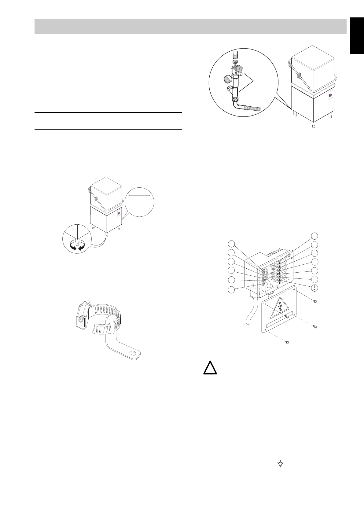
Figure 7
RATING PLATE
The rating plate contains identification and technical
data and is located on the right-hand side panel of the
appliance (Figure 5).
Figure 5
B1 WATER CONNECTION
• The appliance must be fixed to the ground using
the two clamps supplied (Figure 6).
• Check that the dynamic water supply pressure,
measured between the ap pliance and the main, is
between 50 and 700 kPa (test while dishwasher
tank or boiler is filling with water).
If the pressure is too high, fit a suitable pressure reducer on the inlet pipe.
Connect the waste outlet pipe “C” (Figure 4) to the
main drain pipe, fitting a trap, or place the outlet pipe
over an S trap set into the floor.
B2 ELECTRICAL CONNECTION
Figure 6
• Position the dishwasher and level the appliance by
turning the feet (Figure 5).
• Accessing the appliance bottom panel.
• Fit the clamps on feet as shown in supp lied technical sheet.
• Screw the appliance steadily to the ground using
hole clamps.
• Connect the appliance water supply pipe “A”
(Figure 4) to the mains, fitting a cut-off cock, the filter provided and a pressure gauge between the
appliance and the mains (Figure 7).
Figure 8
CAUTION
THE EARTH AND ELECTRICAL CONNECTIONS SHOULD BE IN COMPLIANCE
WITH NATIONAL REGULATIONS.
• Before carrying out the electrical connection, check that
the voltage and frequency on the appliance rating plate
correspond to those of the mains electricity supply.
• The earth wire at the terminal end must be longer
(max. 20 mm) than the phase wires.
• Connect the earth wire of the power supply cable to
an efficient earth clamp. The appliance must also
be included in a unipotential system, the connection being made through the screw “Q” (Figure 4)
marked with the symbol “ ”. The unipotential wire
must have a cross section of 10 mm
2
.
7
Page 6
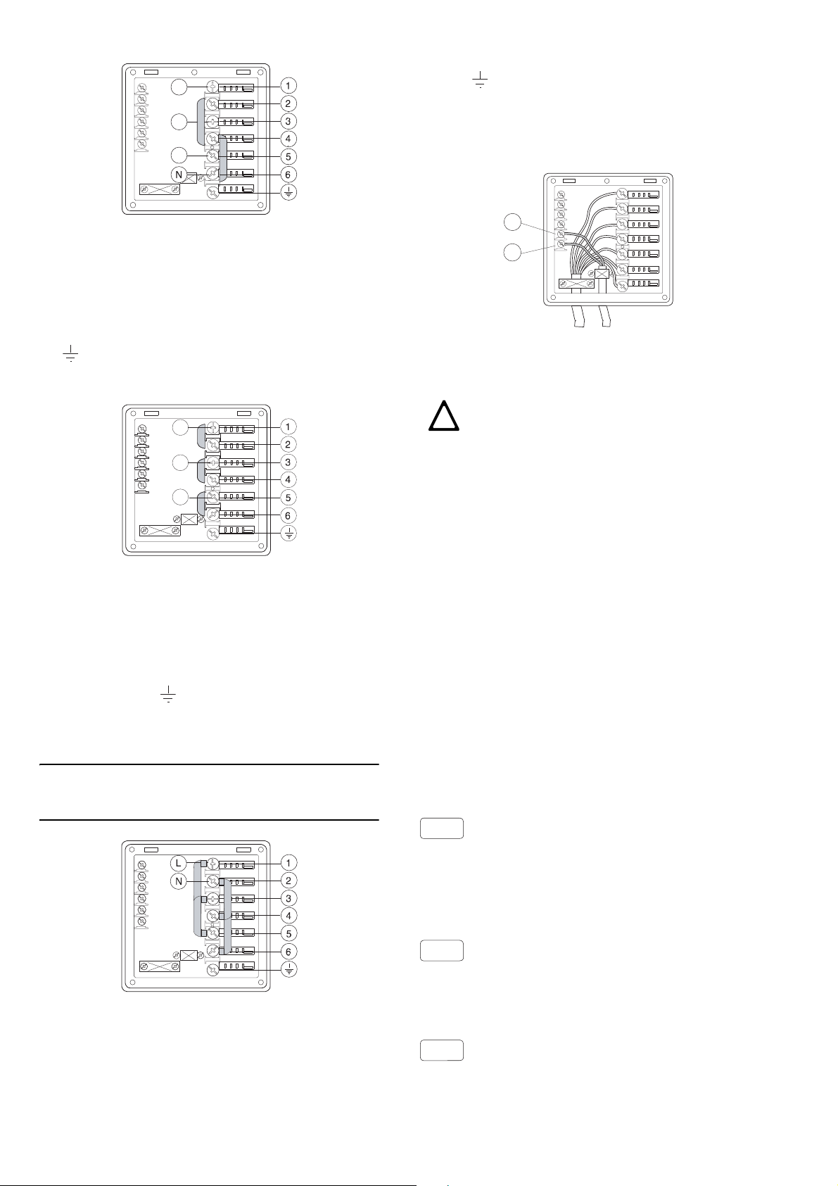
Power supply 400…415V 3N
ATTENTION
L1
L2
L3
11
12
!
A1
B1
B2
Figure 9
Open the power supply terminal board and insert the
jumpers provided as follows: one jumper between terminals 2 and 4 and another between terminals 4 and 6.
Using a suitable power supply cable (see technical data
table), connect the three phases to terminals 1, 3 and 5,
the neutral to terminal 6 and the earth wire to the terminal .
Power supply 220…240V 3
L1
L2
L3
cal data table), connect the phase and neutral to terminals 5 and 6 respectively and the earth wire to the
terminal .
Connections provided for energy control
This appliance is designed for an external energy consumption control.
Figure 12
Connect the energy peak controller across terminals
11 and 12.
CAUTION
A normally open (n.o.) contact of the
controller must be connected across
terminals 11 and 12. When this contact
closes the boiler heating elements are
disconnected. Using the dishwasher in
these conditions may increase the cycle
time.
Figure 10
Open the power supply terminal board and insert the
jumpers provided as follows: one jumper between terminals 1 and 2, one between terminals 3 and 4 and
another between terminals 5 and 6. Using a suitable
power supply cable (see technical data table), connect
the three phases to terminals 1, 3 and 5 and the earth
wire to the terminal .
Power supply 220…240V 1N
Reduce the power of the boiler from 12 kW to 6kW
by connecting the resistors as shown in the circuit
diagram.
Figure 11
Open the power supply terminal board and insert the
jumpers provided as follows: two jumpers between terminals 1, 3, 5 and another two between terminals 2, 4
and 6. Using a suitable power supply cable (see techni-
8
Safety devices
• An automatic reset thermal over-heat device incorporated in the windings of the electric pump cuts off
the electricity supply in the case of malfunctioning .
• In the event of water mains failure, a device prevents water in the boiler from returning into the
mains.
• An overflow pipe, connected to the drainage outlet,
maintains the water in the tank at a constant level.
Failure to comply with safety rules and regulations
relieves the manufacturer of all liability.
B3 WARNING MESSAGES DISPLAYED ON THE
CONTROL P ANEL
NO WATER
- Check that the cock is open.
- Check that the water inlet filter is clean.
- Check the minimum mains pressure.
- Check that the overflow pipe is inserted.
INEFFICIENT DRAINAGE
- Check if the overflow has been removed.
- Check for obstruction on the waste outlet pipe and
the overflow aperture.
TANK WATER LEVEL TOO HIGH
- Check for obstruction on the waste outlet pipe and
the overflow aperture.
Page 7
ENGLISH
CALL THE SERVICE CENTRE
ATTENTION
C1..C8
E1..E8
O
O
Q
P
R
R
CALL THE SERVICE CENTRE
- The appliance continues to operate, but appropriate checks by a technician are recommended.
B4 DETERGENT/RINSE-AID DISPENSERS AND
SETTINGS
If the appliance is connected to a water softener or
osmotic device, contact the detergent supplier for a
specific product.
This machine must be operated with an aut omatic
detergent feeder and, if applicable, an automatic
chemical sanitizer feeder, including a visual means
to verify that detergents and sanitizers are delivered or a visual or audible alarm to signal if detergents and sanitizers are not available for delivery
to the respective washing and sanitizing systems.
Please see instructions for electrical and plumbing
connections located in this manual and in the feeder equipment manual.
Connections for automatic detergent dispenser
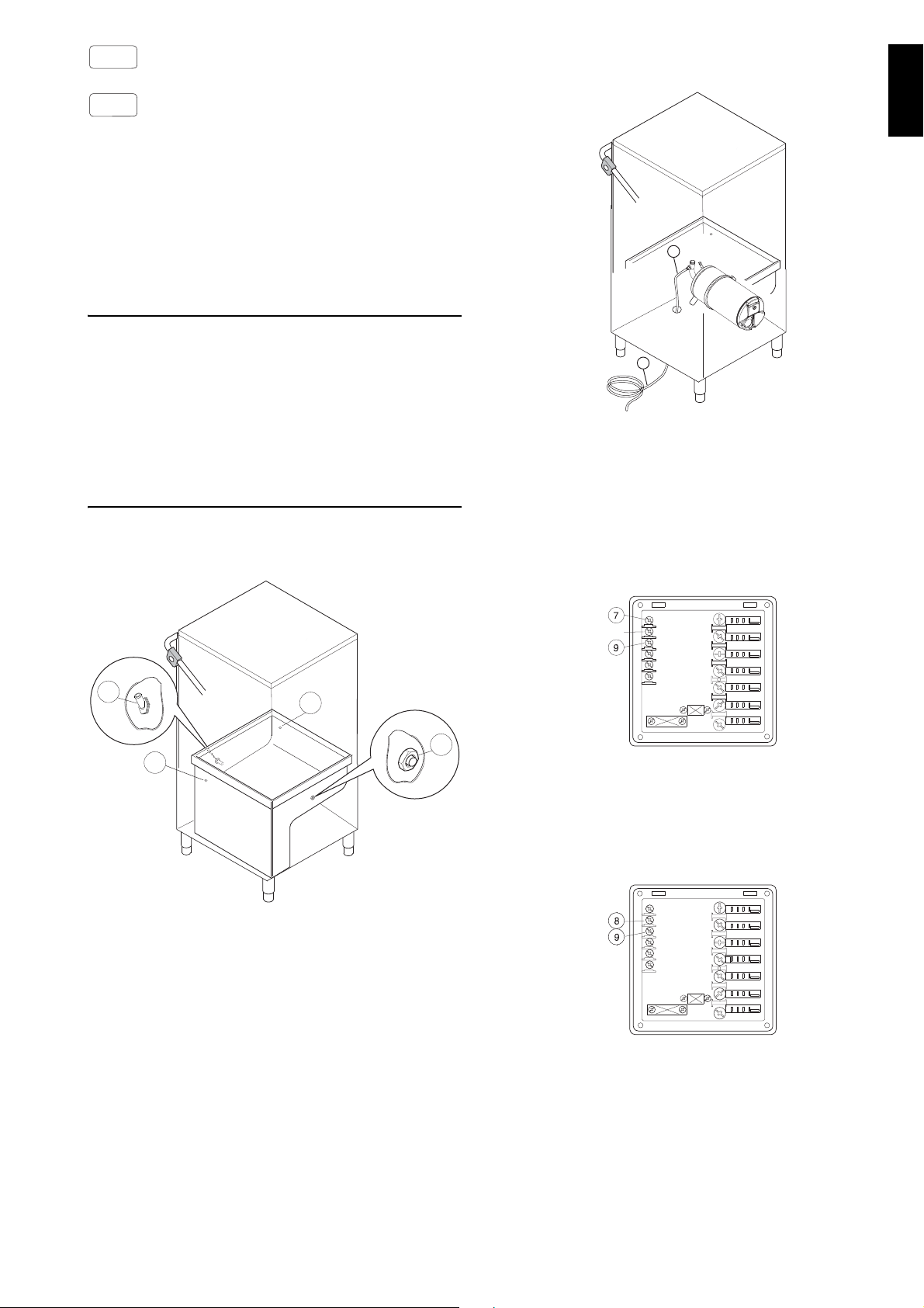
(Figure 13)
Connections for automatic rinse-aid dispenser
(Figure 14)
Figure 14
Connect rinse-aid hose “R” (Figure 14) to automatic
rinse-aid dispenser.
Electrical connections for automatic detergent and
rinse-aid dispensers.
Terminals are available on the power supply terminal
board for the electrical connection of external dispensers working at 220…240 V. Max. power 30 VA.
Figure 15
• Connect the detergent dispenser between terminals 7 and 9. These connection points are live for a
set time during filling of the tank and at the start of
the wash cycle (see paragraph “Setting the dispensers”).
Figure 13
There are two holes (plugged) “O” (Ø 5 mm) for introducing the detergent. These holes may be easily iden tified from outside by looking for the countersunk
marks on the external panel.
Inside the tank there is a hole “P” (Ø 10 mm) closed
with a plug, which may be used for mounting a liquid
detergent injector.
Only ”OHTAROW / OHTAROW60” versions have a
solid detergent injector “Q” (Figure 13) on the back
side of the appliance.
• Connect the rinse-aid dispenser between terminals 8 and 9. These connection points are live during filling of the tank and at the end of the rinse
cycle for a set time (see “setting the dispensers”
paragraph).
Figure 16
9
Page 8
MANUAL ACTIVATION
3
21
33
2211
3
21
3
21
3
21
-
+
3
21
3
21
3
21
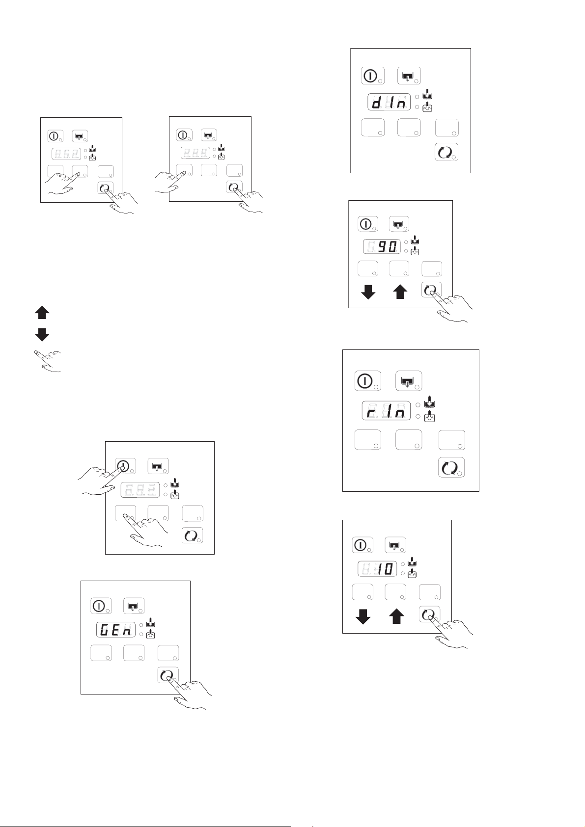
Whenever the detergent containers are replaced, it
may be necessary to activate the dispensers manually
in order to fill the hoses and eliminate any air.
Simultaneously press the buttons, as shown in the
figures below. If necessary, repeat this operation
several times.
DETERGENT DISPENSER RINSE-AID DISPENSER
B5 SETTING THE DISPENSERS
All operations should be carried out with the appliance
switched on, the hood open and no cycle selected.
LEGEND
increase
Initial amount of detergent:
Setting the activation time:
decrease
confirm or select next parameter
SEQUENTIAL START
Press the indicated buttons simultaneously for 5
seconds:
Display of programming mode:
Initial amount of rinse-aid:
Setting the activation time:
-
10
+
Page 9
ENGLISH
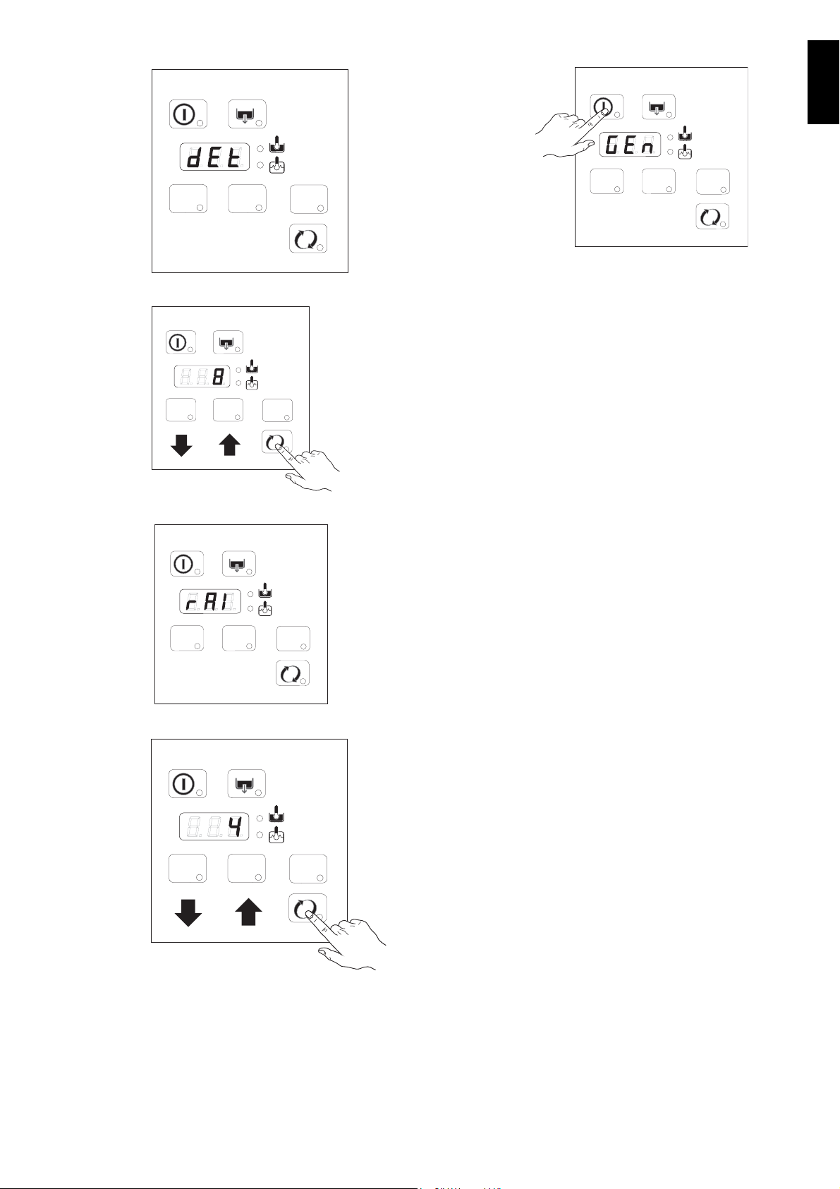
Amount of detergent during the cycle:
3
21
-
+
3
21
3
21
-
+
3
21
3
21
Setting the activation time:
Amount of rinse-aid during the cycle:
Exit from programming mode:
Notes for external dispensers:
dEt=181 the detergent dispenser only
-if
operates during wash pump operation; terminals
7-9 of the main terminal board are powered at the
same time.
-if
dEt=182 the detergent dispenser only
operates during filling electrovalve operation for
restoring the boiler level; terminals 7-9 of the main
terminal board are powered at the same time.
rAi=61 the rinse-aid dispenser only
-if
operates during filling electrovalve operation for
restoring the boiler level; terminals 8-9 of the main
terminal board are powered at the same time.
-if
rAi=62 the rinse-aid dispenser only operates
during wash pump operation; terminals 8-9 of the
main terminal board are powered at the same time.
For connections, see the wiring diagram.
Setting the activation time:
Example:
Supposing that an external detergent dispenser has
been connected with a tank concentration measuring
sensor, a standard setting could be as follows:
dIn=0 the dispenser is not activated during filling of
the tank.
dEt=181 the dispenser is activated during wash
pump operation and, thanks to the concentration
measured by the conduction sensor, the correct
amount of detergent is dispensed.
Suggestion: to check the effectiveness of the rinseaid, look at freshly washed glasses against the light.
Drops of water remaining on the glass indicate an
insufficient amount while streaks indicate an excess.
Changing the detergent/rinse-aid type.
If changing to a different detergent/rinse-aid type
(even one by the same manufacturer), you must rinse
the suction and pressure hoses with fresh water before
connecting the new detergent/rinse-aid container.
Otherwise, the mixing of different types of detergent/
rinse-aid will cause crystallisation, which may result in
a breakdown of the dosing pump. Failure to observe
this condition will invalidate the guarantee and product
liability.
11
Page 10

B6 MAINTENANCE
• Descale the boiler, the internal surfaces of the tank
and the appliance water piping once or twice a
year.
• Descale the rinse and wash jets every month using
vinegar or a descaling agent.
• The internal hose of the rinse-aid and detergent
peristaltic dispenser should undergo periodic maintenance (once or twice a year).
Prolonged period of inactivity
If the dishwasher is not to be used for a long time, proceed as follows:
• Close the water supply cock.
• Completely drain the tank.
• Remove and carefully clean the filters.
• Completely drain the incorporated dispenser
hoses, removing them from the containers. Repeat
the procedure described in the paragraph “Manual
activation” at least 3 times.
• Completely drain the boiler.
• Spread a thin film of Vaseline oil over all the stainless steel surfaces.
Preventive maintenance
The preventive maintenance call may be activated
(see service manuals).
Upon reaching the set number of cycles (e.g. 20000),
appears on the display.
This message advises calling a qualified technician for
a general check-up of the state of the appliance.
12
Page 11
ENGLISH
TIPS
C INSTRUCTIONS FOR THE USER
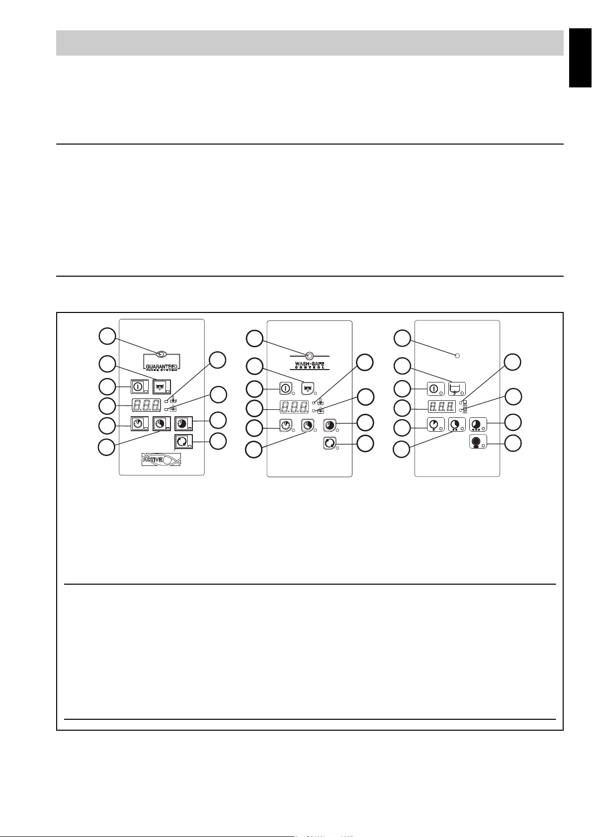
LEGEND:
A = on/off J = wash cycle 1
B = drain/self-cleaning cycle H = wash cycle 2
K =display F = wash cycle 3
D = “tank” indicator light G = High productivity / Thermal label cycle
E = “boiler” indicator light L = Active / Wash Safe Control Led
A
K
J
B
D
E
H
F
G
L
A
K
J
B
D
E
H
F
G
L
A
K
J
B
D
E
H
F
G
L
A
K
J
B
D
E
H
F
G
L
ATTENTION
The GUARANTEED RINSE SYSTEM (GRS) is incorporated in the ACTIVE/ WASH SAFE CONTROL models
(see led “L”).
The GRS is an automatic rinse time/temperature control system.
Operation is as follows:
• during the wash cycle the indicator light is OFF;
• during the rinse cycle the indicator light comes on and is GREEN;
• at the end of the rinse cycle the indicator light remains GREEN if the rinse temperature and time have
been carried out as for the program, otherwise the indicator light becomes RED;
• upon opening the hood, the indicator light GOES OUT.
If the indicator light becomes RED, for example sh ould the boiler waiting time be disabled, wa it for a couple of minutes and then repeat the wash cycle.
Our appliances have been studied and optimised to give high performance. This applia nce must be used e xclusively
for the purpose for which it has been designed, i.e. for washing dishes with water and specific detergents. Any other
use is to be considered improper.
This appliance does not carry out the rinse cycle should there be no supply water; it stops all functions with an error
message “A1” (also see “Warning messages”).
• Carry out a couple of cycles without dishes to flush out any industrial grease which has remained in the
tank and piping.
• Avoid washing decorated dishes.
• Do not allow silverware to come into contact with other metals.
• Do not allow food to dry on the dishes.
• Remove large food scraps from the dishes to prevent clogging the filters.
• Pre-wash the dishes by spraying them with cold or lukewarm water, without using any detergent.
• Use automatic dispensers for the detergent.
• If there is no automatic dispenser, pour a non-foaming detergent into the tank when the water has reached
the washing temperature.
CONTROL PANEL
The temperature shown on the display is that of the boiler if the indi cator lig ht “E” is on or of th e t ank if the light “D” is
on. The tank temperature is displayed during the wash cyc le an d th e bo iler tem per ature during the rinse cycle.
Figure 17
13
Page 12
C1 STARTING
1
2
3
• Open the water supply cock.
• Switch on at the mains.
• Leave the hood and check that all the components
are in their correct position.
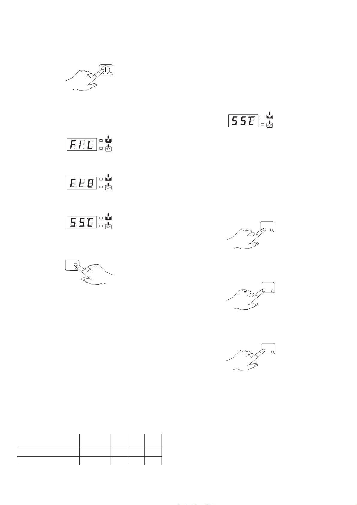
• Close the hood and press button “A”.
The indicator light of button “A” (Figure 17) com es on,
indicating that the dishwasher is powered and that
water is being introduced and heated. The word “FILL”
is shown on the display during the entire filling and
heating stage:
If the hood is opened during this stage the message
“CLOSE” will appear on the display:
The filling and heating stage has finished when the display shows the tank temperature:
A device lengthens the cycle time if the water in the
boiler has not reached the minimum temperature for
correct rinsing.
The cycle times and the temperature may be personalised (e.g. increase of the rinse time and temperature).
The cycle times should only be set by a specialised
technician.
C3 OPERATION
The filling and heating stage has finished when the display shows the tank temperature:
The appliance is then ready for use:
• Leave the hood.
• Pour the required amount of detergent into the tank
(in models without automatic dispenser).
• Insert the rack containing the dirty dishes.
• Close the hood and select the suitable wash cycle;
the corresponding indicator light comes on and the
wash cycle starts:
- Cycle I
For lightly soiled dishes: press button “J” (Figure 17)
(see table of times).
To display the boiler temperature during heating of the
tank, leave the hood and press the button “J”
(Figure 17).
1
C2 WASH CYCLES
The wash cycle includes one wash with hot water and
detergent (min 55 °C) and one rinse with hot water and
rinse-aid (min 82 °C).
T
his machine can operate in 2 modes, "high productivity"
and "thermal label" (factory default).
is configured in "high productivity" mode, the
parameters which define the cycle times and
temperature set points are the standard parameters
(see table of times), whereas when the machine is
configured in "thermal label" mode, the parameter s ar e
specific for this mode and such as to guarantee wash
cycles according to the "thermal label" standards (see
table of times).
Table of times
Standard cycle time with supply water at 10 °C.
ZHTAROW / EHT AROW /
OHTAROW
Thermal label mode
Led “G”
(Figure 17
OFF 77" 90" 150"
High productivity
When the machine
I II III
)
ON 54" 90" 150"
- Cycle II (recommended)
For normally dirty dishes: press button “H” (Figure 17)
(see table of times).
- Cycle III
For very dirty dishes: press button “F” (Figure 17) (see
table of times).
- High productivity / Thermal label cycle
Press and hold button "G" (Figure 17) (see table of
times) to switch from "high productivity" to "thermal
label" mode and vice versa.
The LED corresponding to button "G" is OFF when the
machine is configured in "thermal label" mode (factory
default). The LED switches ON when the button is
pressed and the machine is configured in "high
productivity" mode.
14
Page 13
ENGLISH
• To stop the wash cycle, just press the selected cycle
ATTENTION
ATTENTION
ATTENTION
W
C
button or leave the hood.
• To continue the wash cycle, just press the selected
cycle button or close the hood. The cycle starts again
from where it stopped.
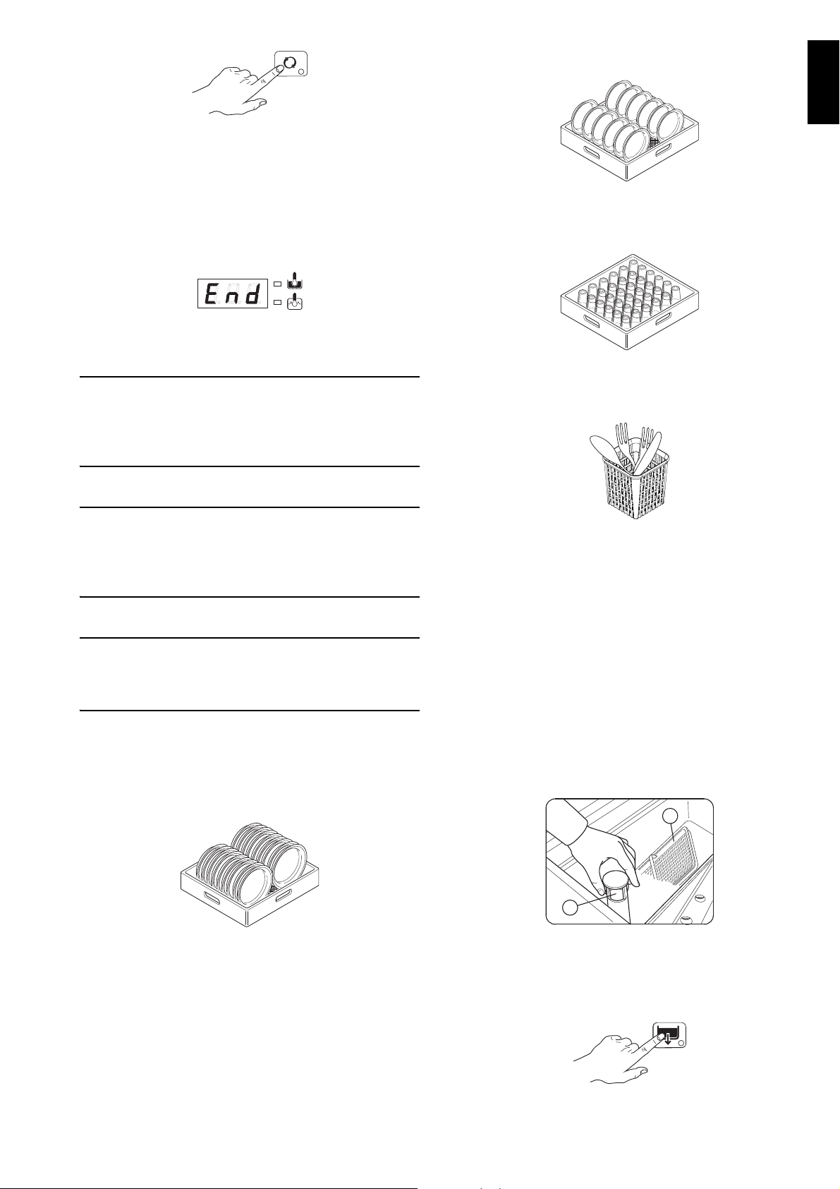
• At the end of the wash, the dishwasher emits a series
of beeps and “END” blinks on the display:
lift the hood and remove the rack containing the
clean dishes.
• GREEN rack: for 12 bowls with maximum diameter
of 240 mm.
Figure 19
• BLUE rack for glasses: the glasses should be
placed upside down.
Figure 20
The appliance will not remove burnt food deposits
from dishes. Dishes with burnt-on food deposits
should be cleaned mechanically/chemically (for
example, pre-wash under running water) before
putting them in the dishwasher.
The use of “foaming”/non-specific detergents or in
any case detergents used in different ways from
that prescribed by the manufacturer, can cause
damage to the dishwasher and compromise washing results.
Failure to remove the residuals of detergent possibly used for manual prewash can cause malfunctioning of the dishwasher and compromise
washing results.
Change the water in the tank at least once a day.
Type of racks and loading
• YELLOW rack: for 18 plates with m aximum diameter of 240 mm.
• YELLOW container for cutlery: insert 15 items, with
the handles pointing downwards, in each container.
Figure 21
• Available as accessories: dividers for glasses a nd
rack for dishes with maximum diameter of 320 mm.
Note: if only one type of dish rack is to be used, it is
advisable to choose the GREEN rack.
C4 END OF WORK AND DAILY CLEANING
The appliance is designed to carry out an automatic
cleaning cycle to help flush out any residues and to
guarantee greater health and hy gie n e:
• Lift the hood and take out the rack containing the
clean dishes.
• Remove the tank filter “C” and the overflow “W” to
drain the water from the tank.
Figure 18
Figure 22
• Close the hood.
• Select the drain cycle by pressing button “B”
(Figure 17).
15
Page 14
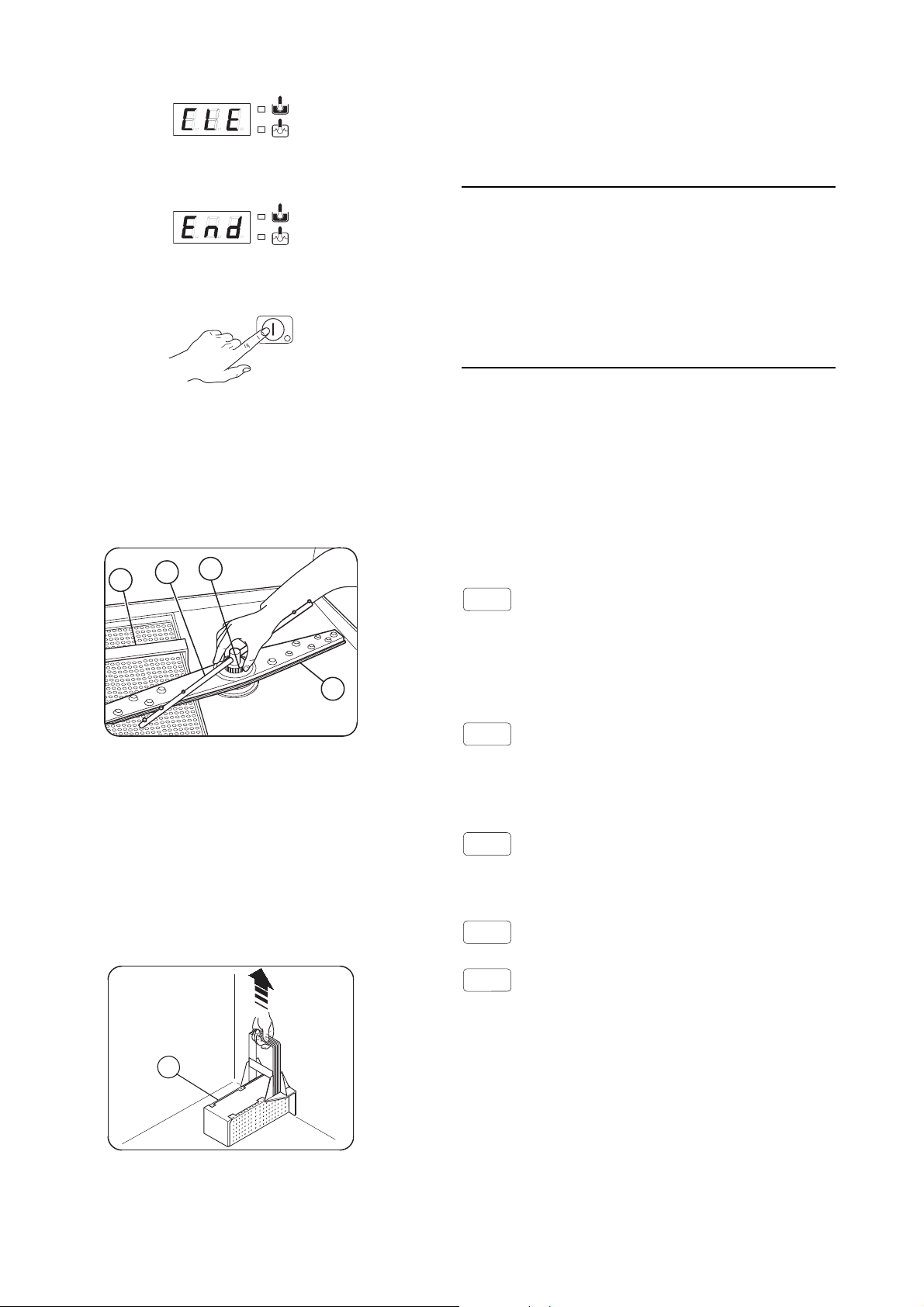
The message "CLE" ("CLEAN") will be displayed
ATTENTION
H
F
I
C
E
A1
B1
B2
C1..C8
E1..E8
throughout the drain cycle:
• After a few minutes, 3 beeps indicate the end of
thecleaning cycle and “END” blinks on the display:
• Switch off the dishwasher by pressing button “A”
(Figure 17).
Upon completion of cleaning operations, replace the
parts removed previously.
Cleaning the exterior surfaces
Before carrying out any cleaning operations, turn off
the power at the mains.
Clean the stainless steel surfaces using warm
soapy water; never use detergents containing
abrasive substances nor steel scrapers, common
wire wool, brushes or scrapers; rinse thoroughly
using a wet cloth and carefully wipe dry.
Clean the control panel using a soft damp cloth
and a neutral detergent if necessary.
Do not wash the appliance using direct or highpressure water jets.
• Switch off at the mains.
• Close the water supply cock.
• Replace the filter and the overflow.
Cleaning the nozzle jets
• Remove the top and bottom jets “F” and “I”,
unscrewing the ring nut “H”.
Figure 23
• Carefully clean the washing and rinse jets and
clean everything with hot water and neutral detergent/detersive, if necessary using a soft brush or
sponge. Do not use sharp implements to clean the
nozzle holes, which could otherwise be damaged.
Cleaning the filter
Remove the filter “E” and clean away any remained
food.
To reduce the emission of pollutants into the environment, clean the appliance (externally and where
necessary internally) with products having a biodegradability of over 90%).
Leave the hood raised whenever the appliance is not
in use.
C5 WARNING MESSAGES DISPLAYED ON THE
CONTROL PANEL
NO WATER
- Check that the cock is open.
- Check that the water inlet filter is clean.
- Check the minimum mains pressure.
- Check that the overflow pipe is inserted.
INEFFICIENT DRAINAGE
- Check if the overflow has been removed.
- Check for obstruction on the waste outlet pipe and
the overflow aperture.
TANK WATER LEVEL TOO HIGH
- Check for obstruction on the waste outlet pipe and
the overflow aperture.
CALL THE SERVICE CENTRE
16
CALL THE SERVICE CENTRE
- Check if the overflow has been removed.
- Check for obstruction on the waste outlet pipe and
the overflow aperture.
C6 RESIDUAL RISKS
The machine has several risks that were not com-
Figure 24
pletely eliminated from a design standpoint or with the
installation of adequate protection devices.
Page 15
ENGLISH
Nevertheless, through this manual the Manufacturer
has taken steps to inform op erators of such risks, carefully indicating the personal protection equipment to be
used by them.
Sufficient spaces are provided for during the machine
installation phases in order to limit these risks.
To preserve these conditions, the corridors and areas
around the machine must always be:
• kept free of obstacles (e.g. ladders, tools, containers, boxes, etc.);
• clean and dry;
• well lit.
For the Customer’s complete information, the residual
risks remaining on the machine are given below; such
actions are to be considered incorrect and therefore
strictly forbidden.
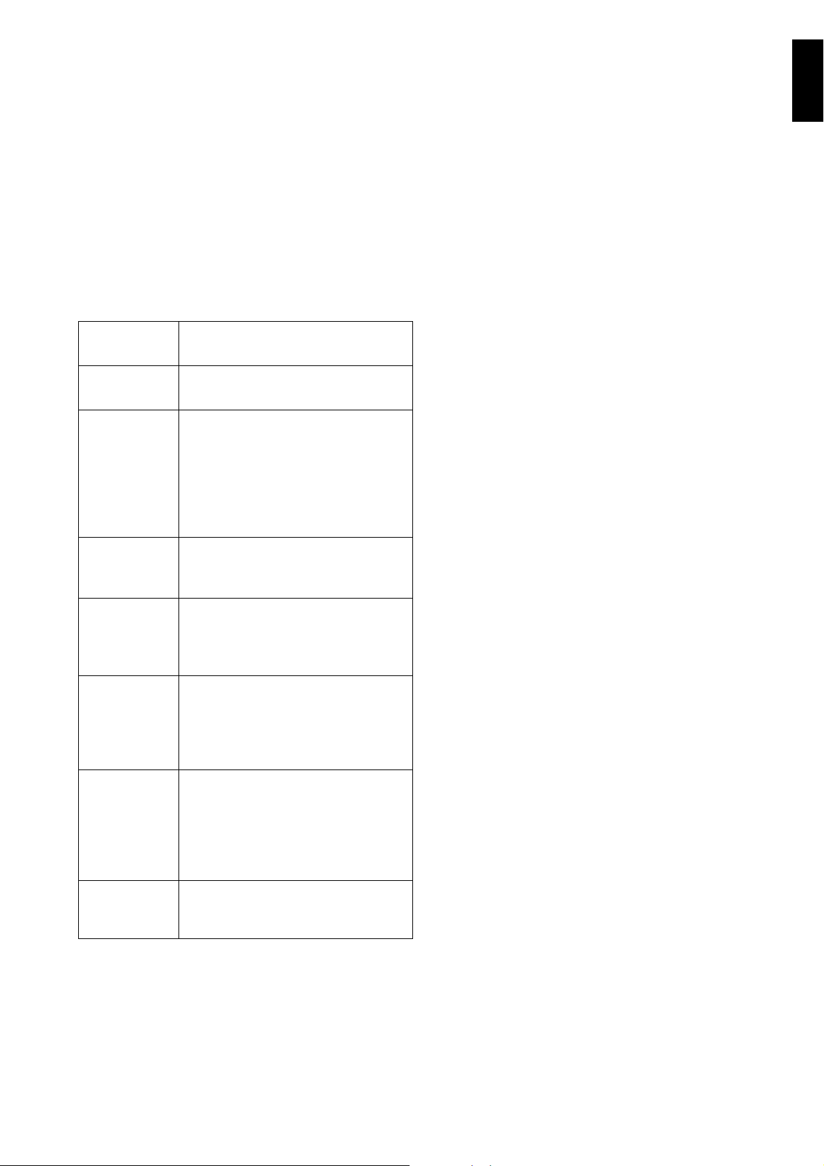
RESIDUAL
RISK
Slipping or
falling
Burns The operator deliberately or unin-
Electrocution Contact with live parts during main-
Falling from
above
Tipping of
loads
DESCRIPTION OF HAZARDOUS
SITUATION
The operator can slip due to water
or dirt on the floor.
tentionally touches some components inside the machine or dishes
at the outfeed without using gloves
or without allowing them to cool.
Possible contact with water above
60°C / 140°F.
tenance operations carried out with
the electrical panel powered.
The operator intervenes on the
machine using unsuitable systems
to access the upper part (e.g. rung
ladders, or climbs on it).
During maintenance on the
machine or the packing containing
the machine with the use of unsuitable accessories or lifting systems
or with load unbalanced.
Chemical Contact with chemical substances
(e.g. detergent, rinse aid, scale
remover, etc.) without taking adequate safety precautions. Therefore always refer to the safety cards
and labels on the products used.
Crushing or
shearing
Possible risk of injury to upper
limbs during the hood closing
operation.
17
Page 16
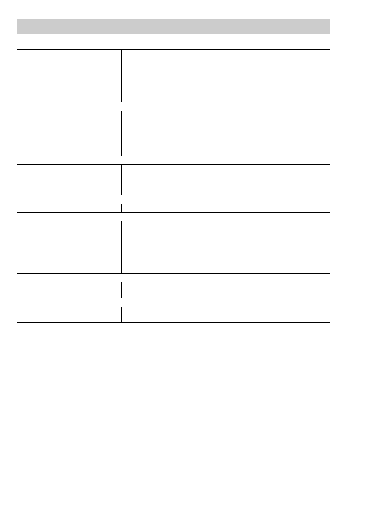
D TROUBLESHOOTING
DISHWASHER DOES NOT WASH
WELL
GLASSES AND DISHES ARE
NOT DRIED PROPERLY
CONDENSATION ON GLASSES 1. Check that there is rinse-aid in the container and if necessary top up.
STAINS ON THE GLASSES 1. Only use “non-foaming” products for professional dishwashers.
EXCESSIVE FOAM IN THE TANK 1. Check that the wash water temperatur e is no t less than 50 °C .
1. Check if the suction filter is dirty and clean it thoroughly.
2. Check if the wash jets are clogged by solid food remains.
3. Check that the initial amount of detergent or subsequent additions are
correct.
4. The selected wash cycle is too short. Repeat the cycle.
5. Check that the tank temperature is between 55 °C and 65 °C.
6. Check that the dishes are stacked correctly in the racks.
1. Check the instructions for the amount of rinse-aid (see “setting the dispensers” paragraph). Check that there is rinse-aid in the container and
if necessary top up.
2. Check the set amount of rinse-aid (see “setting the dispensers” paragraph).
3. Check that the water temperature is between 80 °C and 90 °C.
2. Check the set amount of rinse-aid (see “setting the dispensers” paragraph).
3. Remove the rack of glasses immediately the cycle has ended.
2. Check if the amount of product dispensed by the deterge nt dispenser is
excessive (see “setting the dispensers” paragr ap h ).
3. Ensure that the tank has not been cleaned with unsuitable cleaners.
Drain the tank and rinse thoroughly before new wash cycles.
4. If a foaming detergent has been used, drain and refill the tank with
water until the foam disappears.
SMEARS OR SPOTS ON THE
GLASSES
THE WASH OR RINSE ARMS
TURN SLOWLY
1. Reduce the amount of rinse-aid (see “setting the dispensers” paragraph).
1. Remove and thoroughly clean the arms.
2. Clean the wash pump suction filter.
18
 Loading...