

Page 1

ENGLISH
EN INDEX
A GENERAL INFORMATION .............................................................................. Page 7
A1 Introduction ...................................................................................................................... Page 7
A2 Definitions ........................................................................................................................ Page 7
A3 Typographical conventions .............................................................................................. Page 7
A4 Machine and Manufacturer’s identification data............................................................... Page 7
A5 Equipment identification .................................................................................................. Page8
A5.1 How to identify the technical data........................................................................ Page 8
A5.2 How to interpret the factory description............................................................... Page 8
A6 Copyright ......................................................................................................................... Page 8
A7 Liability............................................................................................................................. Page 8
A8 Personal protection equipment ........................................................................................ Page 9
A9 Keeping the manual......................................................................................................... Page 9
A10 Users of the manual ........................................................................................................ Page 9
B GENERAL DESCRIPTION OF MACHINE ....................................................... Page 10
B1 General description ......................................................................................................... Page 10
C TECHNICAL DATA ........................................................................................... Page 10
C1 Main technical characteristics.......................................................................................... Page 10
C2 Characteristics of power supply....................................................................................... Page 11
D TRANSPORT, HANDLING AND STORAGE.................................................... Page 12
D1 Introduction...................................................................................................................... Page 12
D1.1 Transport: Instructions for the carrier................................................................... Page 12
D2 Handling .......................................................................................................................... Page 12
D2.1 Procedures for handling operations..................................................................... Page 12
D2.2 Translation ........................................................................................................... Page 12
D2.3 Placing the load................................................................................................... Page 12
D3 Storage ............................................................................................................................ Page 12
E INSTALLATION AND ASSEMBLY ................................................................... Page 13
E1 Customer responsibilities ................................................................................................ Page 13
E2 Characteristics of the place of machine installation......................................................... Page 13
E3 Machine space limits ....................................................................................................... Page 13
E4 Positioning ....................................................................................................................... Page 13
E5 Disposal of packing ......................................................................................................... Page 14
E6 Plumbing connections ..................................................................................................... Page 14
E6.1 Plumbing circuits ................................................................................................. Page 14
E6.2 Installation diagrams............................................................................................ Page 15
E7 Electrical connections...................................................................................................... Page 22
E8 Energy control arrangement ............................................................................................ Page 22
E9 HACCP arrangement....................................................................................................... Page 23
F DESCRIPTION OF CONTROL PANEL ............................................................ Page 24
F1 Basic controls .................................................................................................................. Page 25
G STARTING ........................................................................................................ Page 26
G1 Preliminary checks, adjustments and operational tests................................................... Page 26
G1.1 Electrical and plumbing checks ........................................................................... Page 26
G1.2 Check the positioning of tank components.......................................................... Page 26
3
Page 2

G1.2.1 Check the fitting of filters and overflows............................................ Page 26
G1.2.2 Arm fitting check................................................................................ Page 26
G2 Starting ............................................................................................................................Page 26
G3 Detergent/rinse-aid dispensers and settings ...................................................................Page 26
G4 Setting the dispensers .....................................................................................................Page 27
H GENERAL SAFETY RULES.............................................................................Page 30
H1 Introduction ......................................................................................................................Page 30
H1.1 Protection devices installed on the machine........................................................Page 30
H1.1.1 Guards .............................................................................................. Page 30
H1.2 Safety signs to be displayed on the machine or near the work area ................... Page 30
H2 Decommissioning ............................................................................................................ Page 30
H3 Instructions for use and maintenance ..............................................................................Page 30
H4 Improper use....................................................................................................................Page 31
H5 Residual risks .................................................................................................................. Page 31
I NORMAL MACHINE USE.................................................................................Page 32
I1 Correct use ......................................................................................................................Page 32
I2 Characteristics of personnel enabled to operate on the machine....................................Page 32
I3 First use ........................................................................................................................... Page 32
I4 Daily activation of machine ..............................................................................................Page 32
I5 Wash cycles..................................................................................................................... Page 32
I6 Operation ......................................................................................................................... Page 33
I7 Alarms ............................................................................................................................. Page 35
I8 Hood type dishwasher with incorporated continuous water softener............................... Page 35
I9 Machine cleaning............................................................................................................. Page 36
I9.1 End of service and daily internal cleaning ...........................................................Page 36
I9.2 Exterior cleaning..................................................................................................Page 37
I10 Long idle periods .............................................................................................................Page 37
I11 Maintenance ....................................................................................................................Page 37
I11.1 Preventive maintenance ......................................................................................Page 37
I12 Machine disposal.............................................................................................................Page 38
I13 Troubleshooting ...............................................................................................................Page 38
4
Page 3

ENGLISH
EN INDEX OF FIGURES AND TABLES
INDEX OF FIGURES
Figure 1 Reproduction of the marking/dataplate on the machine..................................................... Page 7
Figure 2 Position of marking............................................................................................................. Page 8
Figure 3 Technical data identification ............................................................................................... Page 8
Figure 4 Example of document identification data. .......................................................................... Page 8
Figure 5 Unpacking .......................................................................................................................... Page 13
Figure 6 Machine positioning ........................................................................................................... Page 13
Figure 7 Removing the film ..............................................................................................................Page 13
Figure 8 Feet adjustment ................................................................................................................. Page 13
Figure 9 Machine fixing clamp.......................................................................................................... Page 13
Figure 10 Feed pipe connection......................................................................................................... Page 14
Figure 11 380-415V 3N ...................................................................................................................... Page 22
Figure 12 400-440V 3 ........................................................................................................................ Page 22
Figure 13 220-240V 3 ........................................................................................................................ Page 22
Figure 14 220-240V 1N ...................................................................................................................... Page 22
Figure 15 Energy control .................................................................................................................... Page 22
Figure 16 HACCP connection position............................................................................................... Page 23
Figure 17 Filters and overflow ............................................................................................................ Page 26
Figure 18 Wash and rinse arms ......................................................................................................... Page 26
Figure 19 Automatic dispenser arrangement ..................................................................................... Page 27
Figure 20 Detergent dispenser terminal block.................................................................................... Page 27
Figure 21 Rinse aid dispenser terminal block .................................................................................... Page 27
Figure 22 Automatic hood opening/closing ........................................................................................ Page 33
Figure 23 YELLOW rack..................................................................................................................... Page 34
Figure 24 GREEN rack....................................................................................................................... Page 34
Figure 25 BLUE rack for glasses........................................................................................................ Page 34
Figure 26 YELLOW container for cutlery............................................................................................ Page 34
Figure 27 Unscrew the salt container cap .......................................................................................... Page 36
Figure 28 Add the salt ........................................................................................................................ Page 36
Figure 29 Filters and overflow ............................................................................................................ Page 36
Figure 30 Wash and rinse arms ......................................................................................................... Page 37
INDEX OF TABLES
Ta bl e 1 Main technical characteristics, performance and consumption.......................................... Page 10
Ta bl e 2 Control panel...................................................................................................................... Page 24
Ta bl e 3 Residual risks..................................................................................................................... Page 31
5
Page 4

Foreword
The instruction manual (hereinafter Manual) provides the operator with useful information for working correctly and
safely, facilitating him in using the machine (hereinafter “machine”, “dishwasher” or “equipment”).
The following must not be considered a long and exacting list of warnings, but rather a set of instructions suitable for
improving machine performance in every respect and, above all, preventing injury to persons and animals and damage to property due to improper operating procedures.
All persons involved in machine transport, installation, starting, use and maintenance, repair and dismantling must
consult and carefully read this manual before performing the various operations, for the purpose of avoiding wrong
and improper actions that could negatively affect the machine’s integrity or endanger persons.
The manual must always be available to operators and carefully kept in the place where the machine is used so that
it is immediately at hand for consultation in case of doubts or whenever required.
If, after reading this manual, there are still doubts regarding machine use, do not hesitate to contact the Manufacturer, or the authorized assistance centre, to receive prompt and precise assistance for better operation and maximum efficiency of the machine.
During all phases of machine use, always respect the current regulations on safety, work hygiene and environmental
protection. It is the user’s responsibility to make sure the machine is started and operated only in optimal safety conditions for persons, animals and property.
This appliance is not intended for use by people (including children) with limited physical, sensory or mental abilities
or without experience and knowledge of it, unless they are supervised or instructed in its use by a person responsible for their safety.
Children must be supervised to make sure they do not play with the equipment.
6
Page 5

ENGLISH
A GENERAL INFORMATION
A1 Introduction
This chapter describes the symbols used (that mark
and identify the type of warning) and gives the definitions of terms used in the manual, responsibilities and
copyright.
Emergency stop device
a group of components intended for the emergency
stop function; the device is activated with a single
action and prevents or reduces damage to persons/
machines/property/animals.
Electrocution
an accidental discharge of electric current on a human
body.
A2 Definitions
Listed below are the definitions of the main terms used
in the Manual. Carefully read them before using the
Manual.
Operator
an operator who carries out machine installation,
adjustment, use, maintenance, cleaning, repair and
transport.
Manufacturer
Electrolux Professional S.p.A. or any other assistance
centre authorized by Electrolux Professional S.p.A..
Operator qualified for normal machine use
an operator who has been informed, instructed and
trained regarding the tasks and hazards involved in
normal machine use.
Specialized technician or Technical assistance
an operator instructed/trained by the Manufacturer and
who, based on his professional and specific training,
experience and knowledge of the accident-prevention
regulations, is able to appraise the operations to be
carried out on the machine and recognize and prevent
possible risks. His professionalism covers the mechanical, electrotechnical and electronics fields.
Danger
source of possible injury or harm to health.
Hazardous situation
any situation where an operator is exposed to one or
more hazards.
Risk
a combination of probabilities and risks of injury or
harm to health in a hazardous situation.
Guards
safety measures consisting of the use of specific technical means (guards and safety devices) for protecting
operators against dangers.
Guard
an element of a machine used specifically to provide
protection by means of a physical barrier.
Safety device
a device (other than a guard) that eliminates or
reduces the risk; it can be used alone or in combination with a guard.
Customer
the person who purchased the machine and/or who
manages and uses it (e.g. company, entrepreneur,
firm).
A3 Typographical conventions
For best use of the manual, and therefore the machine,
it is advisable to have good knowledge of the terms
and typographical conventions used in the documentation.
The following symbols are used in the manual to mark
and identify the various types of hazards:
WARNING!
DANGER FOR THE HEALTH AND
SAFETY OF OPERATORS.
WARNING!
DANGER OF ELECTROCUTION - DAN-
GEROUS VOLTAGE.
Machine guards and protection devices marked with
this symbol must only be opened by qualified personnel, after disconnecting the power to the machine.
WARNING!
DANGER OF DAMAGE TO THE
MACHINE.
Words and safety warnings further explaining the type
of hazard are placed next to the symbols in the text.
The warnings are intended to guarantee the safety of
personnel and prevent damage to the machine or the
product being worked.
The drawings and diagrams given in the manual are
not in scale. They supplement the written information
with an outline, but are not intended to be a detailed
representation of the machine supplied.
The numerical values given in the machine installation
diagrams refer to measurements expressed in mm
(see pargraph E6.2 “Installation diagrams”).
A4 Machine and Manufacturer’s identification
data
A reproduction of the marking or dataplate on the
machine is given below.
2012
F.Mod. EHT8I Comm. Model EHT8I
PNC 9CGX 504259 00 Ser.Nr. 22006001
EL AC 400V 3N 50 Hz Max 12.9 kW
Min 6.9 kW
Electrolux Professional spa - Viale Treviso, 15 - 33170 Pordenone (Italy)
(AC 230 V / 1+N / 50 Hz; 230 V / 3 / 50 Hz )
T
Figure 1 Reproduction of the marking/dataplate
on the machine.
Nominal 9.9 kW
IP25
7
Page 6
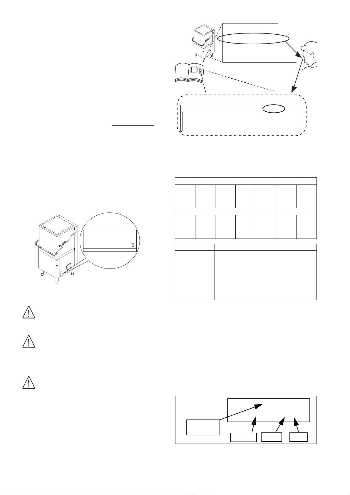
The dataplate gives the product identification and tech-
2012
F.Mod. EHT8I Comm. Model EHT8I
PNC 9CGX 504259 00 Ser.Nr. 22006001
EL AC 400V 3N 50 Hz Max 12.9 kW
(AC 230 V / 1+N / 50 Hz; 230 V / 3 / 50 Hz )
Nominal 9.9 kW
Min 6.9 kW
Electrolux Professional spa - Viale Treviso, 15 - 33170 Pordenone (Italy)
IP25
F.Mod. EHT8I
Electrolux Professional spa - Viale Treviso, 15
C1 Main technical characteristics
MODEL EHT8I
Power supply Electric
Power supply voltage V 400 3N
Frequency Hz 50 or 60
Month YearEdition
Number
Document
nical data; the meaning of the information given on it is
listed below.
F.Mod..................... factory description of the product
Comm. Model ........ trade description
PNC.......................
production code number
Ser. Nr. ................. serial number
AC 400V 3N ......... power supply voltage
(AC 230 V / 1+N / 50 Hz;
230 V / 3 / 50 Hz)
... electric convertibility
50 Hz..................... power supply frequency
Max 12.9 kW ......... max. power absorbed
Nominal 9.9 kW .....
Min 6.9 kW ............
power absorbed as factory setting
power absorbed with min. supply
water temperature of 65°C/ 149°F
2012 ...................... year of construction
CE ......................... CE marking
IP25....................... protection rating
Electrolux Professional spa - Viale Treviso, 15 -33170
Pordenone (Italy)
..... Manufacturer
The marking plate is located on the right side panel of
the equipment.
.
Figure 3 Technical data identification
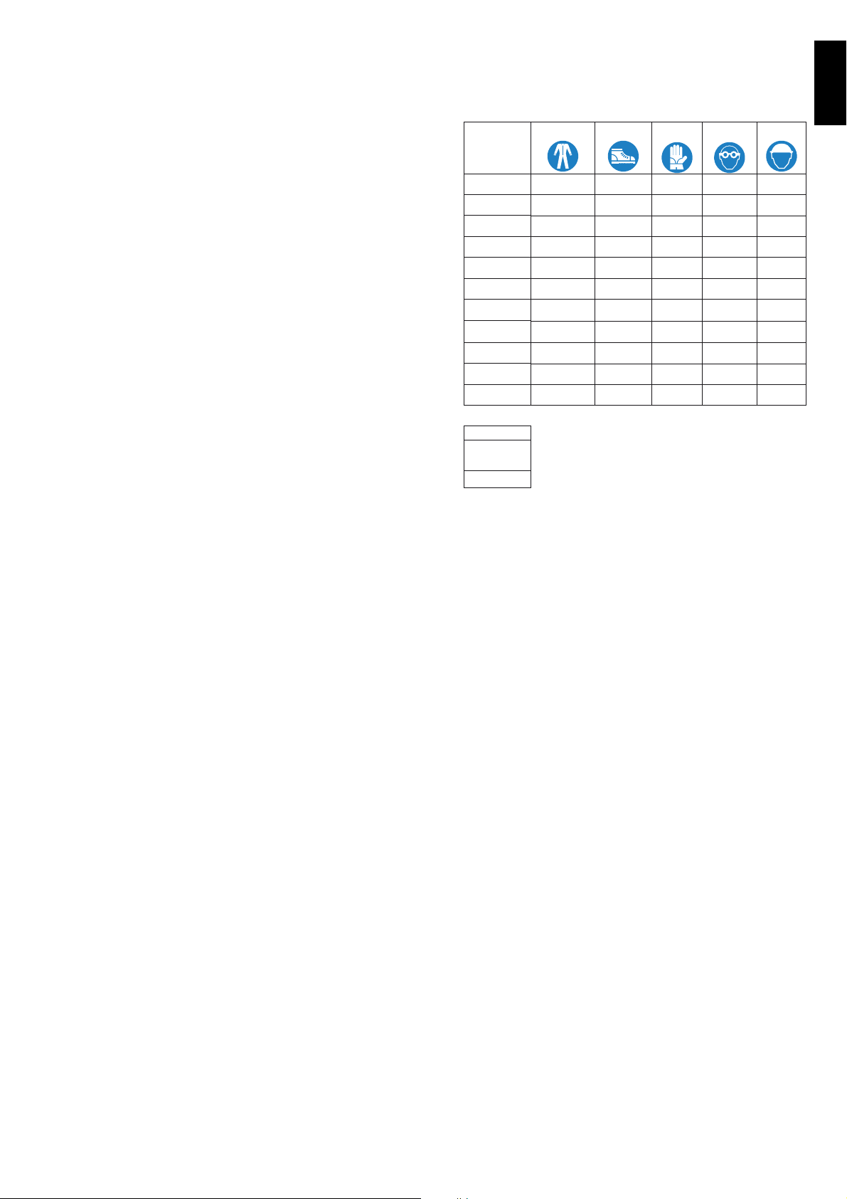
A5.2 How to interpret the factory description
The factory description on the dataplate has the following meaning (some examples are given below):
Single-skin hood version
(1) (2) (3) (4) (5) (6) (7)
NHT8WSG
EHT8 M
Double-skin hood version
(1) (2) (3) (4) (5) (6) (7)
ZHT8 I E L G
EHT8 T I E L
Figure 2 Position of marking
WARNING!
Do not remove, tamper with or make
the machine marking illegible.
IMPORTANT!
Refer to the data given on the machine
marking for relations with the Manufacturer (e.g. when ordering spare parts,
etc.).
IMPORTANT!
When disposing of the machine the
marking must be destroyed.
A5 Equipment identification
A5.1 How to identify the technical data
To identify the technical data (Figure 3) read the factory description of the product (F.Mod.) on the dataplate, identify the main machine data and consult the
Table 1 “Main technical characteristics, performance
and consumption”.
8
Variables description
(1) Mark N = To brand, Z = Zanussi, K = Kipro, A = Alpeninox,
(2) Machine type HT = Hood type
(3) Racks/h 8 = capacity 80 racks/h
(4).. (7) T = automatic, I = double-skin hood, E = Energy
E = Electrolux.
Saving Device, L = De-lime cycle, G = Detergent
pump + rinse aid pump + drain pump, DD =
Detergent pump, WS = Water softener, M = Marine,
USPH = Marine-USPH, 6 = 60 Hz., UK=UK market.
A6 Copyright
This manual is intended for consultation only by the
operator and can be given to third parties only with the
written permission of Electrolux Professional S.p.A..
A7 Liability
The instructions are updated to the month and year
given in the box located at the bottom right of the
cover. The edition corresponds to the manual revision
number. Every new edition replaces and cancels the
previous ones.
DOC. NO. 5956.68U.02
EDITION: 1 04.2013
Figure 4 Example of document identification data.
Page 7
ENGLISH
The Manufacturer declines any liability for damage and
malfunctioning caused by:
• non-compliance with the instructions contained in
this manual;
• repairs not carried out in a workmanlike fashion,
and replacements using spare parts different from
those specified in this manual (the fitting and use of
non-original spare parts and accessories can negatively affect machine operation);
• operations by non-specialized technicians;
• unauthorized modifications or operations;
• inadequate maintenance;
• improper machine use;
• unexpected extraordinary events;
• use of the machine by uninformed and untrained
personnel;
• non-application of the current provisions in the
country of use, concerning safety, hygiene and
health in the workplace.
The Manufacturer declines any liability for damage
caused by arbitrary modifications and conversions carried out by the user or the Customer.
The employer or workplace manager is responsible for
identifying and choosing adequate and suitable personal protection equipment to be worn by operators, in
compliance with current regulations in the country of
use.
Electrolux Professional S.p.A. declines any liability for
possible inaccuracies contained in the manual, if due
to printing or translation errors.
Any supplements to the instruction manual the Customer receives from the Manufacturer must be kept
together with the manual, of which they will form an
integral part.
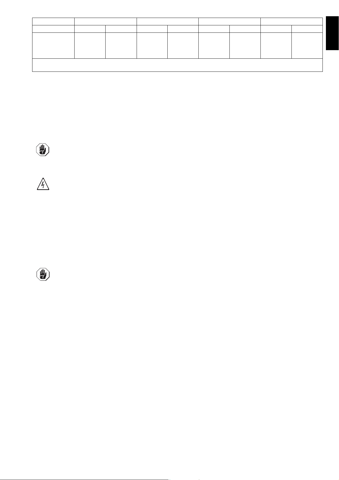
A8 Personal protection equipment
Give below is a summary table of the Personal Protection Equipment (PPE) to be used during the various
stages of the machine’s service life.
Stage
Transport
Handling
Unpacking
Assembly
Normal use
Adjustments
Routine
cleaning
Extraordinar
y cleaning
Maintenance
Dismantling
Scrapping
Key:
Protective
garments
C
M M
F
F
M M M (1)
F
F
F
F
F
F
Safety foot-
wear
M
M
M
M
M M (1)
M M (1)
M
M
M
Gloves Glasses Safety
F
F
F
F
C
CC
CC
CC
F
helmet
F
C
CCC
C
C
F
F
F
F
F
CC
CC
CC
M PPE REQUIRED
F
C
(1)
Use heat resistant gloves suitable for contact with
PPE AVAILABLE OR TO BE USED IF
NECESSARY
PPE NOT REQUIRED
water and the substances used (see the safety data
sheet of the substances used to check other possible
PPE).
Failure to use the personal protection equipment by
operators, specialised technicians or users can involve
exposure to chemical risk and possible damage to
health.
A9 Keeping the manual
The manual must be carefully kept for the entire life of
the machine until decommissioning.
The manual must stay with the machine in case of
transfer, sale, hire, granting of use or leasing.
A10 Users of the manual
This manual is intended for:
• the carrier and handling personnel;
• installation and start-up personnel;
• the employer of machine users and the workplace
manager;
• operators in charge of normal machine use;
• specialized technicians - technical assistance (see
wiring diagram and service manual).
9
Page 8

B GENERAL DESCRIPTION OF MACHINE
B1 General description
The dishwasher is suitable for washing dishes, glasses, cups, cutlery, trays, containers and receptacles in plastic
and/or steel used for preparing, cooking and serving; as well as various cooking utensils in ceramic and/or metal.
The machine is designed for the above-mentioned applications. Under no circumstances may the machine be used
for other applications or ways not provided for in this manual.
This equipment has been produced to meet the needs for a better work environment and economical efficiency.
These dishwashers are used in restaurants, cafeterias, cooking centres and large institutions.
The special dish racks, that can be equipped with various inserts, offer practical and easy use for obtaining excellent
washing results. The electronic system enables complete supervision of the washing process. The control panel
also has a display that shows the operating parameters and signals any anomalies.
Systems for scraping and wetting the dishes (e.g. manual prewash spray) and areas for sorting and arranging them
in the racks must be arranged ahead of the dishwasher.
C TECHNICAL DATA
C1 Main technical characteristics
MODEL NHT8/ EHT8/
Supply voltage: V 400V 3N 400V 3N(°) 400V 3 440V 3 400V 3N
- convertible to V 230V 3 230V 3(°) - - 230V 3
- convertible to V 230V 1N 230V 1N(°) - - 230V 1N
Frequency Hz 50 50 or 60 50 60 50
Max. power. absorbed kW 12,9 (*) 12,9 (*) 12,9 (*) 12,9 (*) 12,9 (*)
power absorbed as factory setting
Power absorbed with min. supply water
temperature of 65°C / 149°F
Boiler heating elements kW 9,0 9,0 9,0 9,0 9,0
Tank heating elements kW 3.0 3,0 3,0 3,0 3,0
Water supply pressure kPa [bar] 50-700 [0,5-7] 50-700 [0,5-7] 50-700 [0,5-7] 50-700 [0,5-7] 50-700 [0,5-7]
Water supply temperature:
- for models without ESD °C/ °F 10-65 / 50-149 10-65 / 50-149 10-65 / 50-149 10-65 / 50-149 10-65 / 50-149
- for models with ESD °C/ °F - 10-20 / 50-68 - - 10-20 / 50-68
Water supply hardness for models without
incorporated continuous water softener
Water supply hardness for models with
incorporated water softener
Electric conductivity of water for models without
incorporated continuous water softener
Concentration of chlorides in water ppm < 20 < 20 < 20 < 20 < 20
Rinse cycle water consumption l 2,0 2,0 2,0 2,0 2,0
Boiler capacity l12 12 12 12 12
Tank capacity l24 24 24 24 24
Cycle duration in High Productivity mode ($) sec. 45(***)-84-150 45(***)-84-150 45(***)-84-150 45(***)-84-150 45(***)-84-150
Cycle duration in ETL-Sanitization mode ($) sec. 57(***)-84-150 57(***)-84-150 57(***)-84-150 57(***)-84-150 57(***)-84-150
Legal noise level Leq dB(A) <68 <63 <68 / <63 <68 / <63 <63
Protection rating IP25 IP25 IPX5 IPX5 IP25
Net weight without/with ESD kg 106 / - 117 / 150 117 / - 117 / - 119 / 152
Power supply cable H07RN-F H07RN-F H07RN-F H07RN-F H07RN-F
Supply cord diameter (min. - max. value) mm 18 - 25 18 - 25 18 - 25 18 - 25 18 - 25
Latent heat without/with ESD kWh 0,5/ - 0,5/ 0,35 0,5/ - 0,5/ - 0,5/ 0,35
Sensible heat without/with ESD kWh 2/ - 2/ 1,49 2/ - 2/ - 2/ 1,49
(*) = If activated by software, coincidence of tank and boiler heating elements.
(**) = Activatable via software only by a specialized technician.
(***) = With water supply temperature at 65°C / 149°F.
($) = In models with energy saving device (ESD) cycle duration is extended by 11 seconds.
(°) = For the model EHT8IELG6: 380-400V 3N convertible 220-230V 3 or 220-230V 1N.
kW 9,9 9,9 9,9 9,9 9,9
kW 6,9 (**) 6,9 (**) - - 6,9 (**)
°f/°d/°e 14/8/10 max 14/8/10 max 14/8/10 max 14/8/10 max 14/8/10 max
°f/°d/°e 53.4/30/37.5 max 53.4/30/37.5 max - - -
S/cm < 400 < 400 < 400 < 400 < 400
KHT8
ZHT8I / AHT8I /
EHT8I / NHT8I
EHT8M /
EHT8IUSPH5
EHT8M6/
EHT8IUSPH6
ZHT8TIL/
EHT8TIL
10
Table 1 Main technical characteristics, performance and consumption
Page 9
ENGLISH
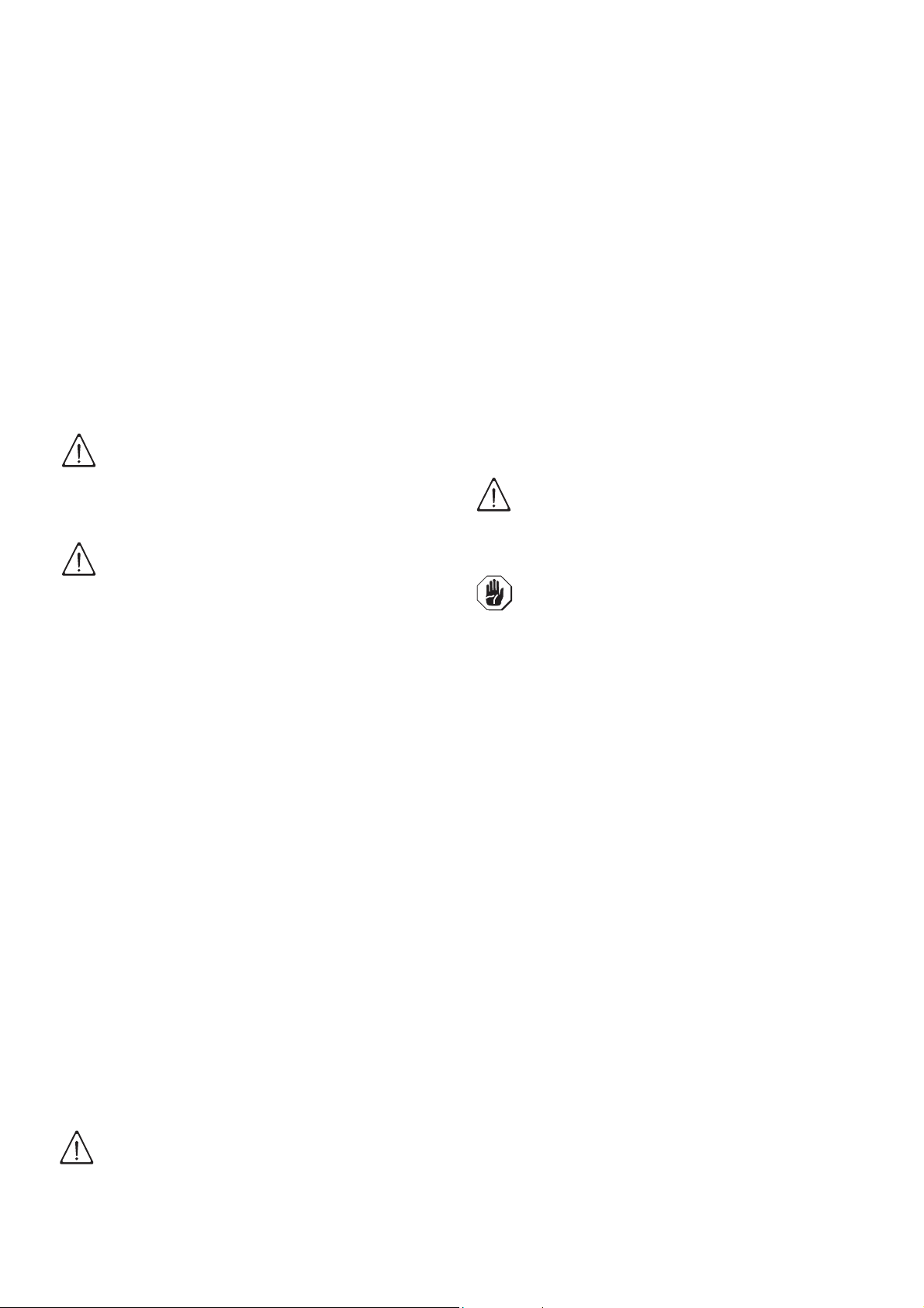
380-415V 3N 400-440V 3 220-240V 3 220-240V 1N
CSCSCSCS
6,9 kW
9,9 kW
12,9 kW
C = Power supply cable
S = On/Off switch
5X2,5 mm
5X2,5 mm
5X4 mm
2
2
2
16A 3P+N
20A 3P+N
32A 3P+N
5X2,5 mm
4X2,5 mm
4X4 mm
2
16A 3P
2
20A 3P
2
25A 3P
4X10 mm
4x4 mm
4X6 mm
2
20A 3P
2
32A 3P
2
50A 3P
3X10 mm
3X10 mm
3x6 mm
2
2
2
40 A 1P+N
60 A 1P+N
70 A 1P+N
Standard cycle time may vary should the inlet water temperature be different from that indicated above.
C2 Characteristics of power supply
The AC power supply to the machine must meet the following conditions:
• max. voltage variation ± 10%
• max. frequency variation ± 1% continuous ± 2% for a short period.
Harmonic distorsion, unbalanced three-phase supply voltage, voltage pulses, interruption, dips and the other electric
characteristics must respect the provisions of point 4.3.2 of Standard EN 60204-1 (IEC 60204-1).
IMPORTANT!
The machine’s power supply must be protected against overcurrents (short circuits and over-
loads) by fuses or suitable thermal magnetic circuit breakers.
These must be fitted on an omnipolar disconnection system having a contact gap of at least 3 mm.
IMPORTANT!
For protection against indirect contacts (depending on the type of supply provided for and con-
nection of earths to the equipotential protection circuit) refer to point 6.3.3 of EN 60204-1 (IEC
60204-1) with the use of protection devices that ensure automatic cut-off of the supply in case of
isolation fault in the TN or TT systems or, for IT systems, the use of isolation controllers or differential current protection devices to activate automatic power disconnection (an isolation controller must be provided for indicating a possible first earth fault of a live part, unless a protection
device is supplied for switching off the power in case of a such a fault. This device must activate
an acoustic and/or visual signal which must continue for the entire duration of the fault).
For example: in a TT system, a differential switch with cut-in current (e.g. 30 mA) coordinated
with the earthing system of the building where the machine is located must be installed ahead of
the supply.
IMPORTANT!
Customers are requested to follow these instructions, otherwise the Manufacturer does not guar-
antee the machine for continuous operation and/or against faults.
11
Page 10
D TRANSPORT, HANDLING AND STORAGE
D1 Introduction
Transport (i.e. transfer of the machine from one place
to another) and handling (i.e. transfer inside workplaces) must occur with the use of special equipment
of adequate capacity.
The machine must only be transported, handled and
stored by qualified personnel, who must have:
- specific technical training and experience;
- knowledge of the safety regulations and applicable
laws in the relevant sectors;
- knowledge of the general safety provisions;
- the ability to recognize and avoid any possible hazard.
D1.1 Transport: Instructions for the carrier
WARNING!
Do not stand under suspended loads
during the loading/unloading phases.
Unauthorized personnel must not
access the work zone.
IMPORTANT!
The machine’s weight alone is not suf-
ficient to keep it steady.
The transported load can shift:
- when braking;
- when accelerating;
- in corners;
- on particularly rough roads.
D2.2 Translation
The operator must:
• have a general view of the path to be followed;
• stop the manoeuvre in case of hazardous situations.
D2.3 Placing the load
Before placing the load make sure the path is free and
that the floor is flat and can take the load.
D3 Storage
The machine and/or its parts must be stored and
protected against damp, in a non-aggressive place
free of vibrations and with room temperature of
between -10°C / 14°F and 50°C / 122°F.
The place where the machine is stored must have a
flat support surface in order to avoid any twisting of the
machine or damage to the support feet.
IMPORTANT!
Machine positioning, installation and
disassembly must be carried out by a
specialized technician.
IMPORTANT!
Do not make modifications to the parts
supplied with the machine. Any missing or faulty parts must be replaced
with original parts.
D2 Handling
Arrange a suitable area with flat floor for machine
unloading and storage operations.
D2.1 Procedures for handling operations
For correct and safe lifting operations:
• use the type of equipment most suitable for characteristics and capacity (e.g. lift trucks or electric pallet truck);
• cover sharp edges;
• check the forks and lifting procedures according to
the instructions given on the packing.
Before lifting:
• send all operators to a safe position and prevent
persons from accessing the handling zone;
• make sure the load is stable;
• make sure no material can fall during lifting, and
manoeuvre vertically in order to avoid impacts;
• handle the machine, keeping it at minimum height
from the ground.
CAUTION!
For machine lifting, do not use movable or weak parts such as casings,
electrical raceways, pneumatic parts,
etc., as anchoring points.
12
Page 11

ENGLISH
E INSTALLATION AND ASSEMBLY
IMPORTANT!
Machine installation operations must
only be carried out by specialized Technicians provided with all the appropriate
personal protection equipment (safety
shoes, gloves, glasses, overalls, etc.),
tools, utensils and ancillary means.
E1 Customer responsibilities
The Customer must provide for the following:
- Install a disconnecting switch with a capacity at
least equal to that given in the technical data table,
a 30mA residual current circuit breaker and an
overcurrent device (magnetothermal cut-out with
manual reset or fuse) between the appliance and
the mains power outlet. The chosen device must be
lockable in the open position in case of maintenance.
- install an adequate electrical power supply ahead
of the machine, according to the equipment’s technical specifications (Table 1 and C2 “Characteristics of power supply”);
- the equipotential connection of the workplace electrical system to the metal structure of the machine
by means of a copper cable of adequate section
(see position “EQ” in par. E6.2 “Installation diagrams”);
- Adducting for the electrical connection between the
workplace electric panel and the equipment;
- the water supply and drain connections and other
connections as indicated in Table 1 and par. E6
“Plumbing connections”;
Arranging the machine:
• Wear protective gloves and unpack the machine
(Figure 5).
Figure 5 Unpacking
• Lift the appliance using a lift truck, remove the base
and position the appliance where it is to be installed
(Figure 6).
Figure 6 Machine
positioning
Figure 7 Removing
the film
E2 Characteristics of the place of machine
installation
The machine is designed for installation in professional
and not domestic-type kitchens. Water collection traps/
metal grates must be arranged in the floor at the
machine discharges (see pargraph E6.2 “Installation
diagrams”), possibly replaceable with a single water
trap sized for a flow rate of at least 3 l/s.
E3 Machine space limits
A suitable space must be left around the machine (for
operations, maintenance, etc.).
The passages enabling personnel to operate on the
machine must be at least 50 cm wide, except at the
rear of the machine.
The size must be increased in case of use and/or
transfer of other equipment and/or means or if exit
routes are necessary inside the workplace.
E4 Positioning
The machine must be taken to the place of installation
and the packing base removed only when being
installed.
• Carefully remove the protective film from the outer
panels without tearing it, to avoid leaving traces of
glue (Figure 7).
• Adjust the equipment by turning the special adjustable feet and making sure it is perfectly level, both
lengthwise and crosswise (Figure 8).
Figure 8 Feet adjustment
• The appliance must be fixed to the floor using the
two clamps supplied (Figure 9).
Figure 9 Machine fixing clamp
13
Page 12
• Accessing the appliance bottom panel.
IMPORTANT
PS
!
• Fit the clamps on feet as shown in supplied technical sheet.
Screw the appliance steadily to the floor using hole
•
clamps
E5 Disposal of packing
All materials used for packing are environmentally
compatible. They can be safely kept, and recycled or
burnt in a special waste incineration plant. Plastic parts
subject to possible recycling are marked as follows:
PE
PP
Parts in wood and cardboard can be disposed of
respecting the current regulations in the country of
use.
E6 Plumbing connections
.
polyethylene: outer wrapping, instruc-
tion booklet bag.
polypropylene: roof packing panels,
straps.
polystyrene
foam:
corner protectors.
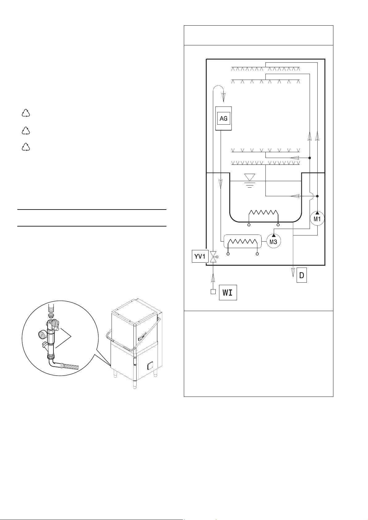
E6.1 Plumbing circuits
Plumbing circuit diagram - manual hood type
without drain pump
Watermark labelled machines must be installed in
accordance with AS/NZS 3500.1.
Install the machine water filling and drain pipes according to the plumbing circuit and installation diagrams
given below.
• Connect the appliance water supply pipe “WI” (see
paragraph E6.2 Installation diagrams) to the mains,
fitting a cut-off cock, the filter provided and a pressure gauge between the appliance and the mains
(Figure 10).
Figure 10 Feed pipe connection
LEGEND
WI = Water inlet
CWI = Cold water inlet (~ 15°C)
M1 = Wash pump
M3 = Rinse pump
M4 = Drain pump
M9 = ESD fan motor
M10 = ESD fan motor
AG = Air Gap
YV1 = Filling solenoid valve
V = Ventilation
• Check that the dynamic water supply pressure,
measured between the appliance and the main, is
between 50 and 700 kPa (test while dishwasher
tank or boiler is filling with water).
If the pressure is too high, fit a suitable pressure reducer on the inlet pipe.
• Connect the waste outlet pipe “D” (see pargraph
E6.2 Installation diagrams) to the main drain pipe,
fitting a trap, or place the outlet pipe over an S trap
set into the floor.
14
Page 13
ENGLISH
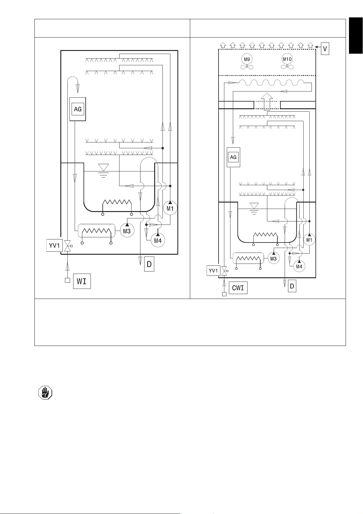
Plumbing circuit diagram - manual hood type with drain
pump
Plumbing circuit diagram - automatic hood type with
energy saving device (ESD)
LEGEND
WI = Water inlet
CWI = Cold water inlet (~ 15°C)
M1 = Wash pump
M3 = Rinse pump
M4 = Drain pump
M9 = ESD fan motor
M10 = ESD fan motor
AG = Air Gap
YV1 = Filling solenoid valve
V = Ventilation
E6.2 Installation diagrams
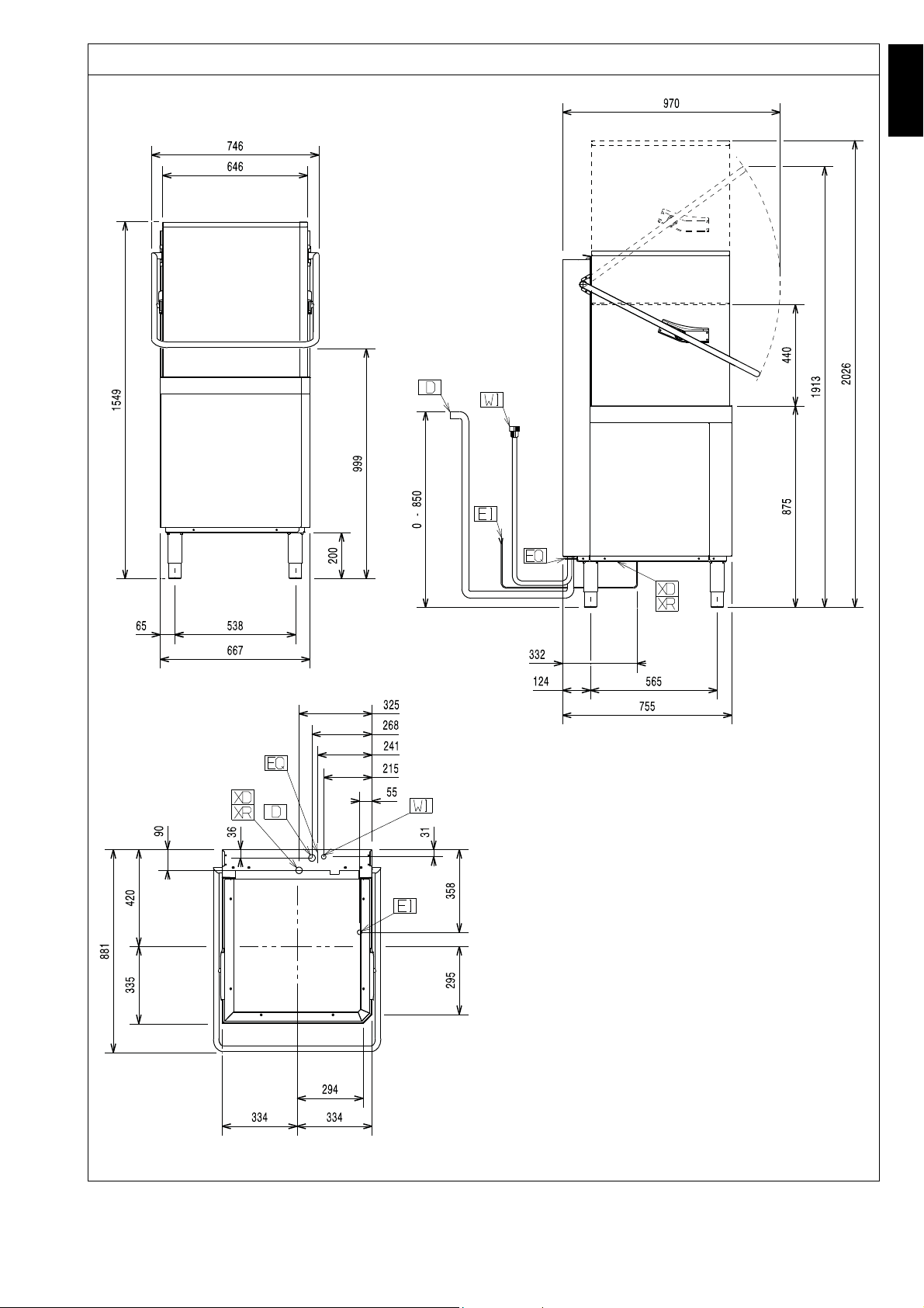
The following installation diagrams give the machine overall dimensions and position of water and electrical connections.
IMPORTANT!
For models without energy saving device (ESD), make sure to install an extractor hood to remove
the steam produced by the machine.
For models with energy saving device (ESD), it is not necessary to install an extractor hood
unless the current regulations in the country of use require it.
The hood air flow must be calculated taking into account the type of installation and the work
environment where it is installed. In any case, an air flow rate of between 1000 m
3
/h and 1500 m3/
h is recommended.
15
Page 14
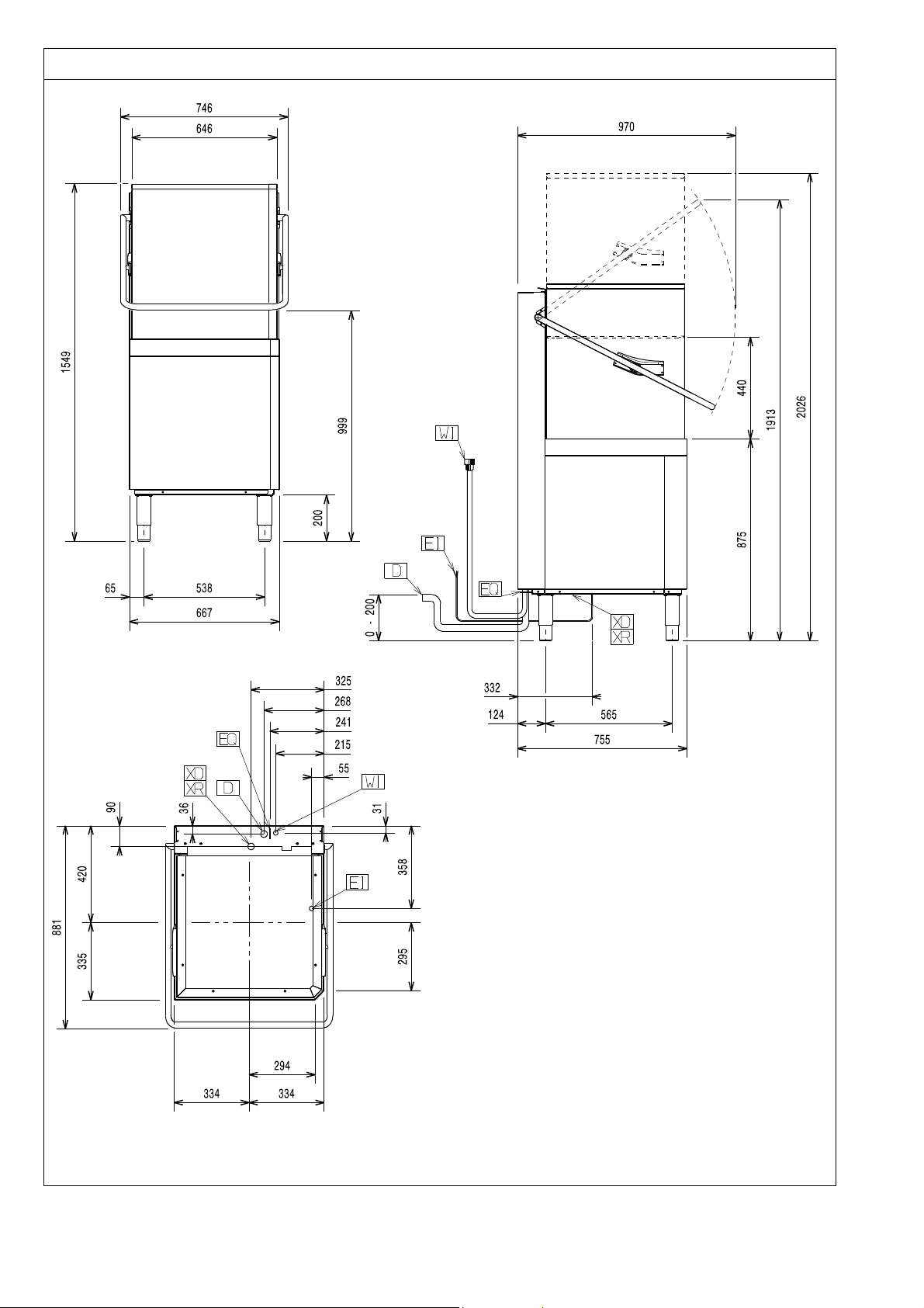
Installation diagram - manual hood type (single skin) without drain pump and without energy saving device (ESD)
LEGEND
WI Water inlet
CWI Cold water inlet
D Drain outlet
EI Power supply entry
EQ Equipotential screw
V Ventilation
XD Pipe inlet for detergent
XR Pipe inlet for rinse aid
XI Pipe inlet for de-lime
16
Page 15
ENGLISH
Installation diagram - manual hood type (single skin) with drain pump and without energy saving device (ESD)
LEGEND
WI Water inlet
CWI Cold water inlet
D Drain outlet
EI Power supply entry
EQ Equipotential screw
V Ventilation
XD Pipe inlet for detergent
XR Pipe inlet for rinse aid
XI Pipe inlet for de-lime
17
Page 16
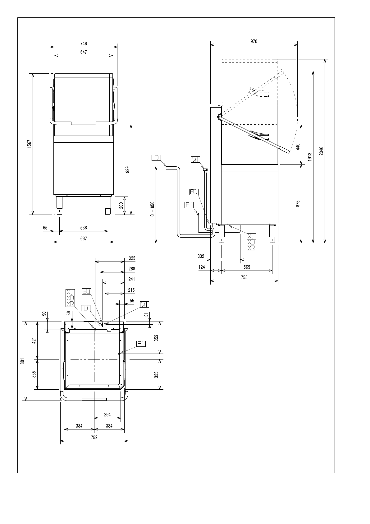
Installation diagram - manual hood type (double skin) with drain pump and without energy saving device (ESD)
LEGEND
WI Water inlet
CWI Cold water inlet
D Drain outlet
EI Power supply entry
EQ Equipotential screw
V Ventilation
XD Pipe inlet for detergent
XR Pipe inlet for rinse aid
XI Pipe inlet for de-lime
18
Page 17
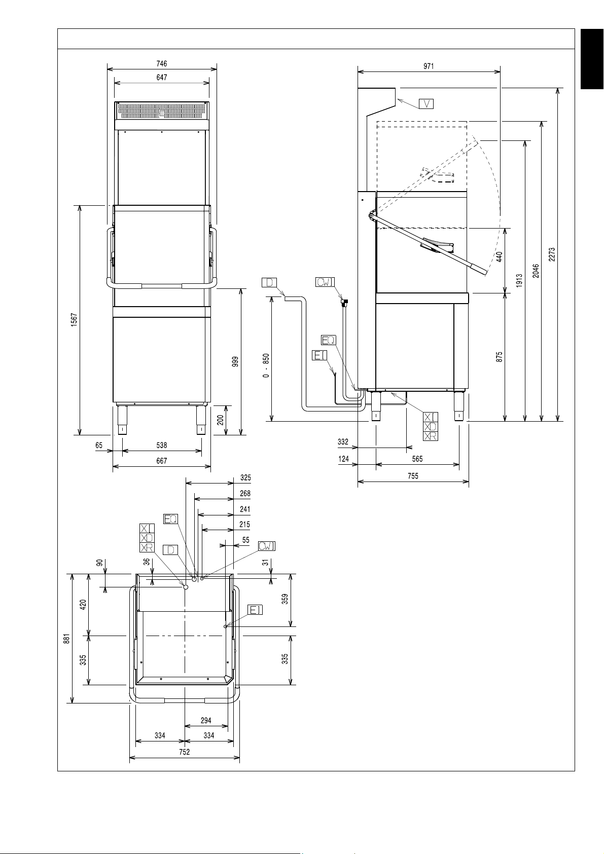
ENGLISH
Installation diagram - manual hood type (double skin) with drain pump and with energy saving device (ESD)
LEGEND
WI Water inlet
CWI Cold water inlet
D Drain outlet
EI Power supply entry
EQ Equipotential screw
V Ventilation
XD Pipe inlet for detergent
XR Pipe inlet for rinse aid
XI Pipe inlet for de-lime
19
Page 18
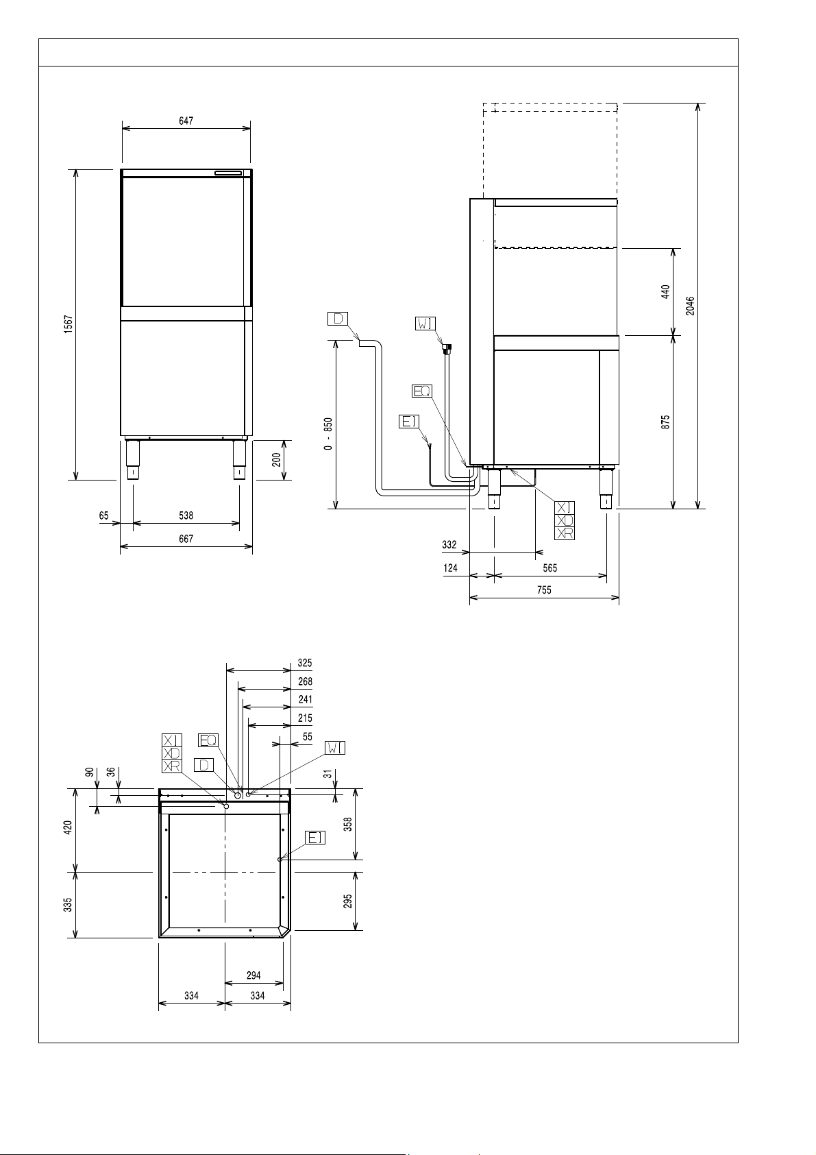
Installation diagram - automatic hood type with drain pump and without energy saving device (ESD)
LEGEND
WI Water inlet
CWI Cold water inlet
D Drain outlet
EI Power supply entry
EQ Equipotential screw
V Ventilation
XD Pipe inlet for detergent
XR Pipe inlet for rinse aid
XI Pipe inlet for de-lime
20
Page 19
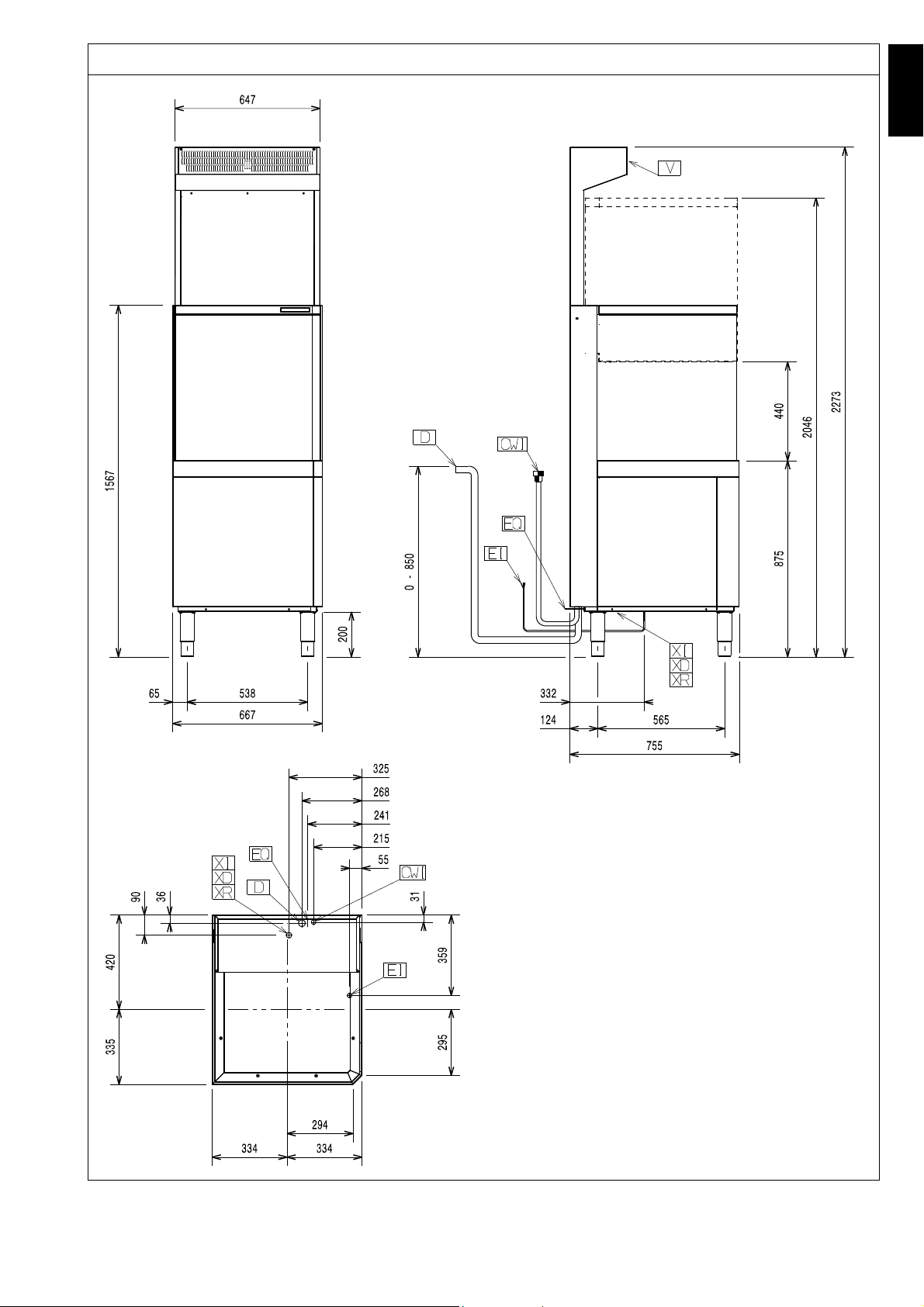
ENGLISH
Installation diagram - automatic hood type with drain pump and with energy saving device (ESD)
LEGEND
WI Water inlet
CWI Cold water inlet
D Drain outlet
EI Power supply entry
EQ Equipotential screw
V Ve nti lati on
XD Pipe inlet for detergent
XR Pipe inlet for rinse aid
XI Pipe inlet for de-lime
21
Page 20
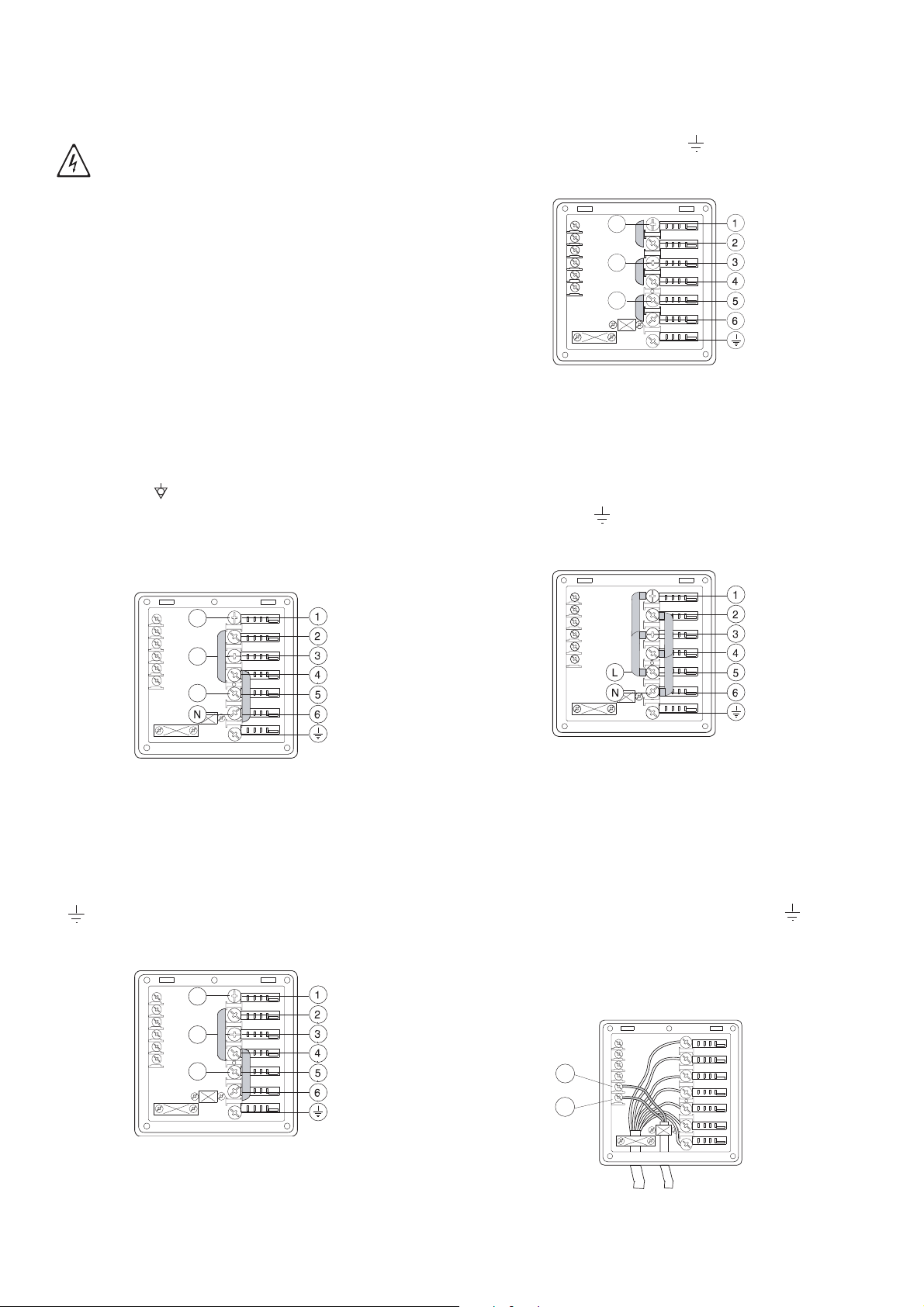
E7 Electrical connections
L1
L2
L3
L1
L2
L3
L1
L2
L3
Connection to the power supply must be carried out in
conformity with the current regulations and provisions
in the country of use.
IMPORTANT!
Work on the electrical systems must
only be carried out by a qualified electrician.
• Make sure the machine power supply voltage specified on the rating plate (Table 1) matches the
mains voltage.
• Make sure the system power supply is arranged
and able to take the actual current load and that it is
executed in a workmanlike manner according to the
regulations in force in the country of use.
• The earth wire at the terminal end must be longer
(max. 20 mm) than the phase wires.
• Connect the earth wire of the power supply cable to
an efficient earth clamp. The appliance must also
be included in a unipotential system, the connection being made through the screw “EQ” (see
pargraph E6.2 Installation diagrams) marked with
the symbol “ ”. The unipotential wire must have a
cross section of 10 mm2.
Open the power supply terminal board and insert the
jumpers provided as follows: two jumpers between terminals 2 and 4 and two between terminals 4 and 6.
Using a suitable power supply cable (see technical data
table), connect the three phases to terminals 1, 3 and 5
and the earth wire to the terminal .
Power supply 220-240V 3
Figure 13 220-240V 3
Open the power supply terminal board and insert the
jumpers provided as follows: one jumper between terminals 1 and 2, one between terminals 3 and 4 and
another between terminals 5 and 6. Using a suitable
power supply cable (see technical data table), connect
the three phases to terminals 1, 3 and 5 and the earth
wire to the terminal .
Power supply 380-415V 3N
(standard configuration)
Figure 11 380-415V 3N
Open the power supply terminal board and insert the
jumpers provided as follows: two jumpers between ter-
minals 2 and 4 and two between terminals 4 and 6.
Using a suitable power supply cable (see technical data
table), connect the three phases to terminals 1, 3 and 5,
the neutral to terminal 6 and the earth wire to the terminal .
Power supply 400-440V 3
Power supply 220-240V 1N
Figure 14 220-240V 1N
Open the power supply terminal board and insert the
jumpers provided as follows: two jumpers between terminals 1 and 3, two jumpers between terminals 2 and 4, one
jumper between terminals 3 and 5 and another two
between terminals 4 and 6.
Using a suitable power supply cable (see technical data
table), connect the phase and neutral to terminals 5 and
6 respectively and the earth wire to the terminal .
E8 Energy control arrangement
The machine is arranged for external control of energy
consumption.
22
11
12
Figure 12 400-440V 3
Figure 15 Energy control
Page 21
ENGLISH
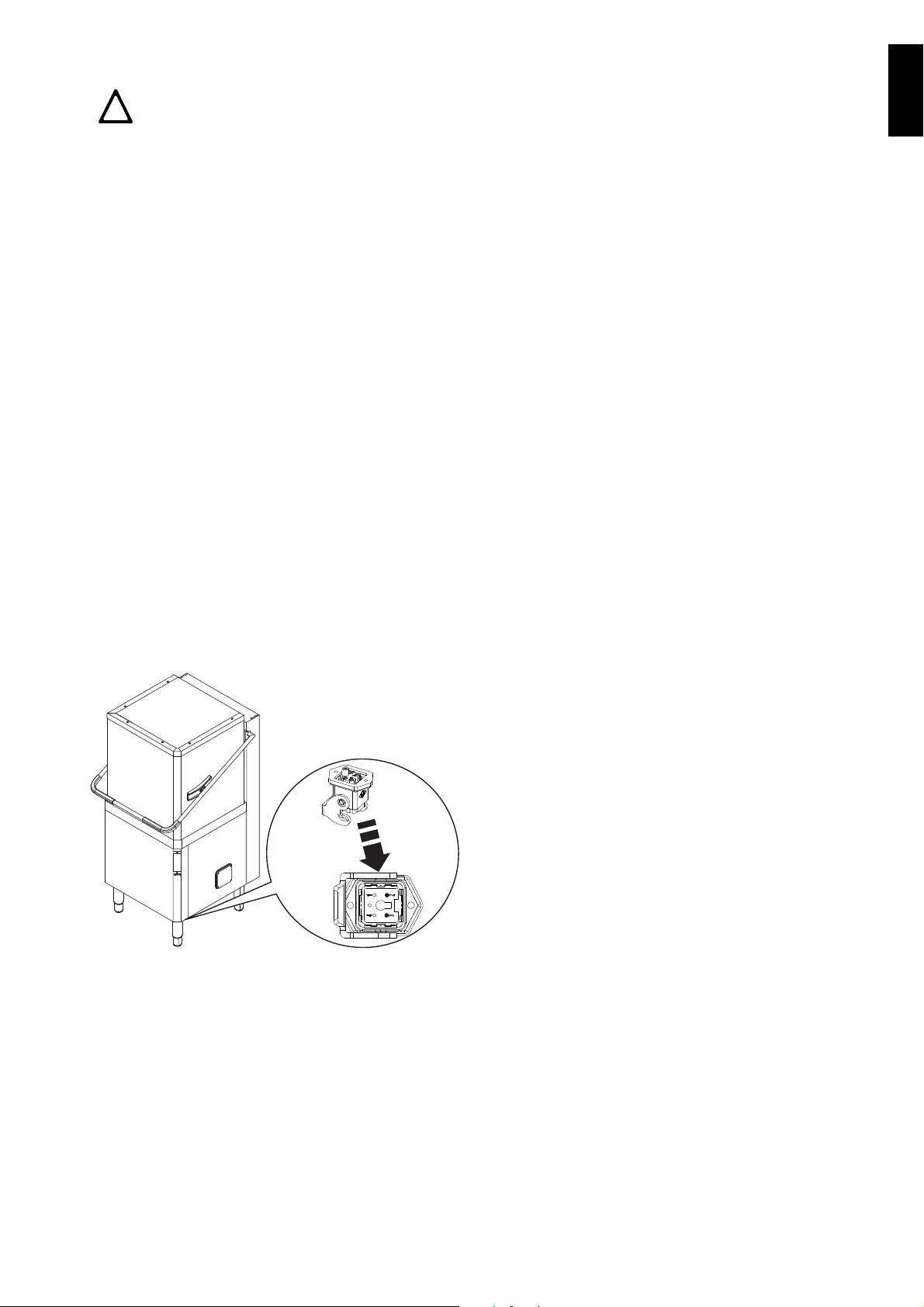
Connect the energy peak controller across terminals
!
11 and 12 (Figure 15).
CAUTION
A normally open (n.o.) contact of the con-
troller must be connected across terminals 11 and 12. When this contact closes
the boiler heating elements are disconnected. Using the dishwasher in these
conditions may increase the cycle time.
Safety devices
• An automatic reset thermoamperometric protective
device incorporated in the windings of the electric
pump cuts off the electricity supply in the case of
malfunctioning.
• In the event of water mains failure, a device prevents water in the boiler from returning into the
mains.
• An overflow pipe, connected to the drainage outlet,
maintains the water in the tank at a constant level.
Failure to comply with safety rules and regulations
relieves the manufacturer of all liability.
E9 HACCP arrangement
In some models the machine is not arranged for the
HACCP connection; however, an HACCP kit can be
ordered as an accessory.
When the machine is arranged for the HACCP connection it is still necessary to order the network connection cable.
Connect the HACCP network to terminals 2 and 3 of
connector X4.
Figure 16 HACCP connection position
23
Page 22
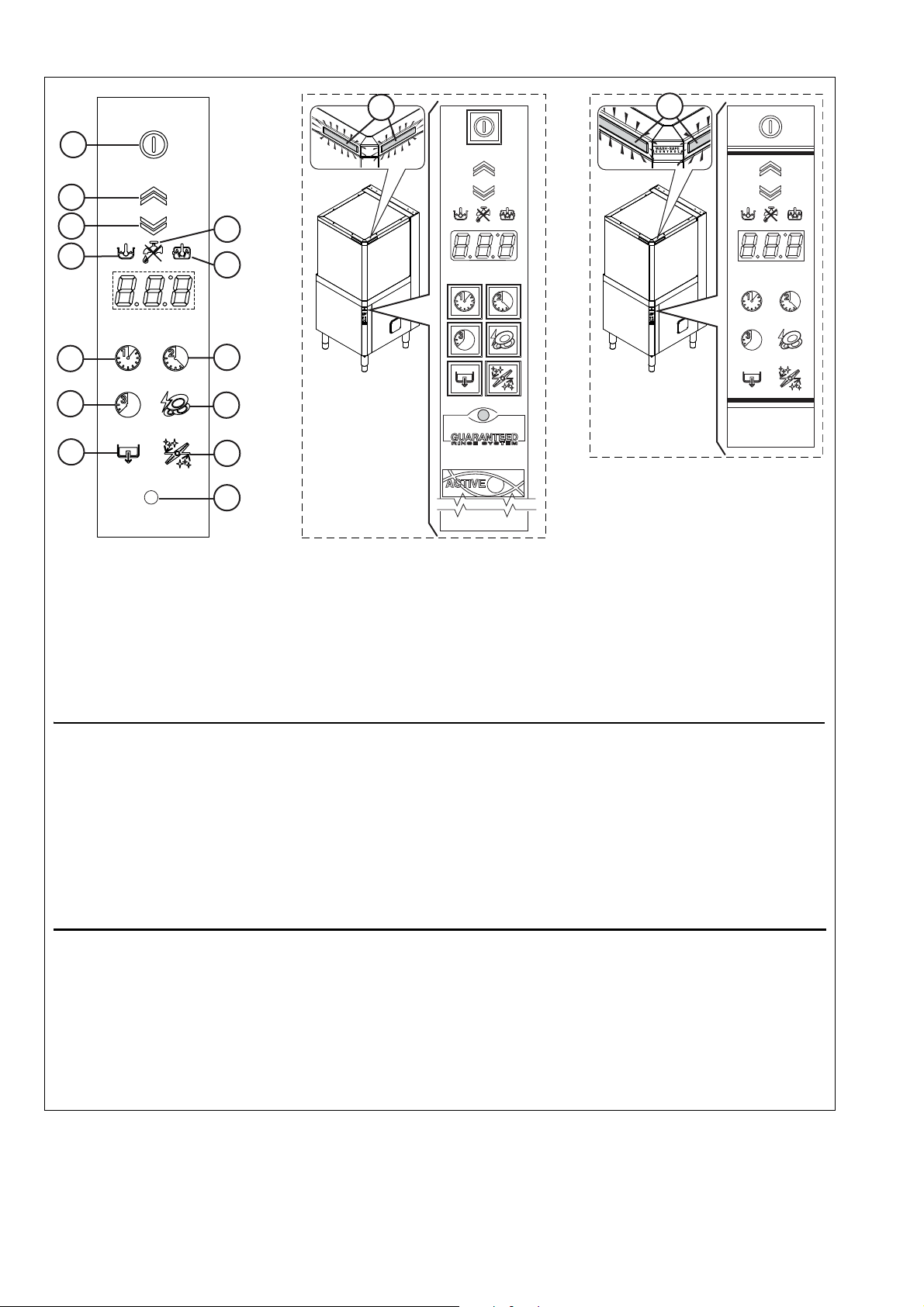
F DESCRIPTION OF CONTROL PANEL
Legend
A = On / Off
B = Open hood
C = Close hood
D = “Tank temperature” indicator
light
E = “Water tap” indicator light
F = “Boiler temperature”
indicator light
G = Wash cycle 1
H = Wash cycle 2
I = Wash cycle 3
L = High Productivity or ETL-
Sanitization
M = Drain / self-cleaning cycle
N = Delime cycle
P = ACTIVE/ WASH SAFE
CONTROL
Q = LED bar
IMPORTANT
The GUARANTEED RINSE SYSTEM (GRS) is incorporated in the ACTIVE/ WASH SAFE CONTROL models
(see led “P”). The GRS is an automatic rinse time/temperature control system.
Operation is as follows:
• during the wash cycle the indicator light is OFF;
• during the rinse cycle the indicator light comes on and is GREEN;
• at the end of the rinse cycle the indicator light remains GREEN if the rinse temperature and time have
been carried out as per the programme, otherwise the indicator light becomes RED;
• upon opening the hood, the indicator light GOES OUT.
If the indicator light becomes RED, for example should the boiler waiting time be disabled, wait for a couple of minutes and then repeat the wash cycle.
The temperature shown on the display is that of the tank if the light “D” is on, or of the boiler if the indicator light
“F” is on. The tank temperature is displayed during the wash cycle and the boiler temperature during the rinse
cycle.
In automatic versions the machine has a LED bar "Q" which monitors equipment status. When the LED bar is
green the machine is ready for washing and when it is blue it indicates wash cycle progress status. After rinsing,
the LED bar remains green if the temperature and rinse time were as programmed, otherwise the LED bar turns
RED.
B
A
C
L
H
D
E
F
I
N
M
G
P
Q
Q
Described below are all the single keys and functions present in the various control panel models listed above. Some
functions are shared by all models of the range, whereas others are available only on several versions.
Table 2 Control panel
24
Page 23
ENGLISH
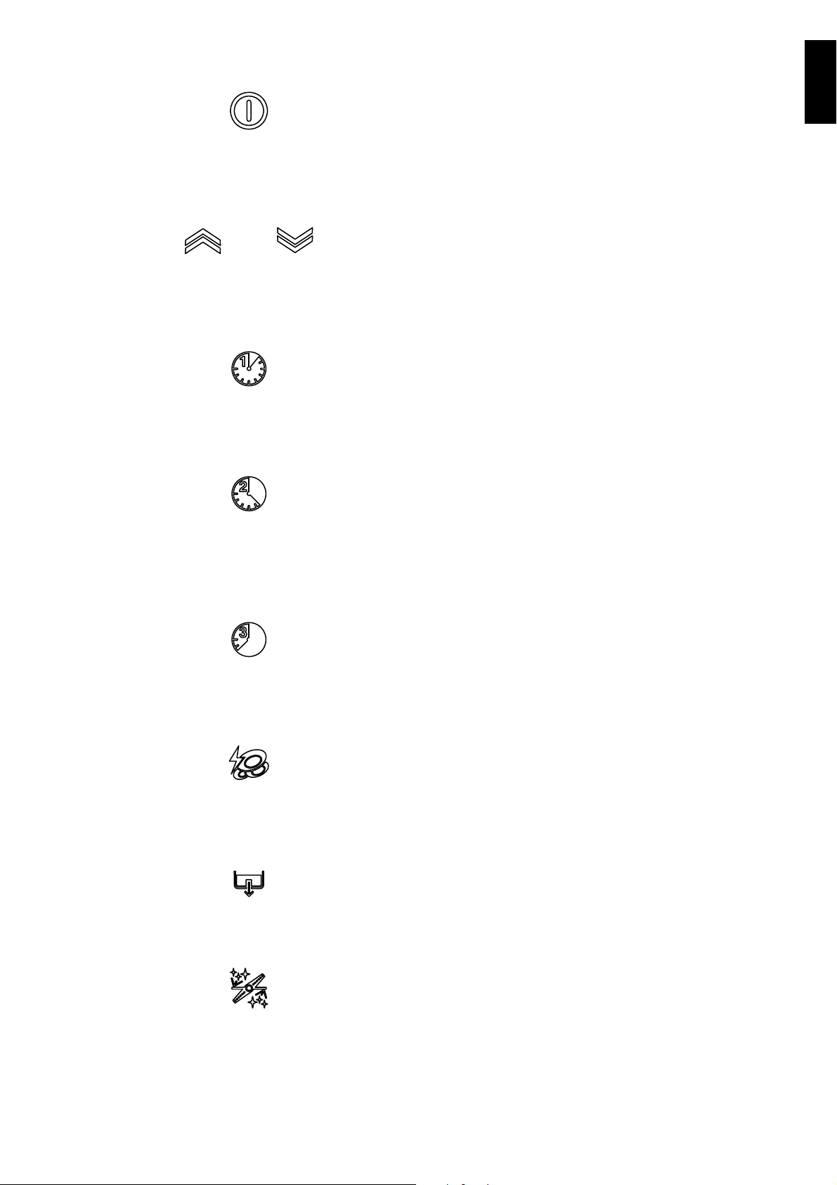
F1 Basic controls
On/Off
This key indicates the status of the equipment: on or
off. When the appliance is on, the key is lit.
Hood opening/closing (for automatic versions
only)
These buttons open/close the hood, only in automatic
versions.
Wash cycle 1
This button starts wash cycle 1. This cycle is recommended for washing not very dirty dishes.
Wash cycle 2
This button starts wash cycle 2. This cycle is recommended for washing normally dirty dishes.
Wash cycle 3
This button starts wash cycle 3. This cycle is recommended for washing very dirty dishes.
High Productivity or ETL-Sanitization mode
This button is used to go from High Productivity wash
mode to ETL-Sanitization mode and vice versa.
Drain / self-cleaning cycle
This button starts a drain / self-cleaning cycle.
Delime cycle
This button is used to run a machine water circuit
delime cycle with vinegar.
When a cycle is selected, the corresponding button is
lit up.
25
Page 24
GSTARTING
IMPORTANT
3
B
2
1
2
1
3
4
A
G1 Preliminary checks, adjustments and
operational tests
IMPORTANT!
These operations must only be carried
out by specialized technicians provided with adequate personal protection equipment (e.g. safety footwear,
gloves, glasses, etc.), tools and suitable ancillary equipment.
G1.1 Electrical and plumbing checks
Before starting the machine:
• check correct connection of the electrical wires that
feed the machine;
• make sure the power supply voltage and frequency
match the data given in Table 1;
• check correct connection of the water supply and
drain pipes (see par. E6 “Plumbing connections”);
• make sure all the guards and safety devices are in
place and efficient.
G1.2 Check the positioning of tank components
IMPORTANT!
The following operations must be car-
ried out by operators provided with
suitable personal protection equipment
(e.g. protective gloves, etc.) with the
machine switched off and cold.
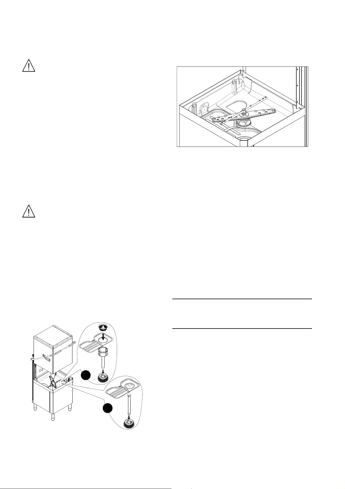
G1.2.1 Check the fitting of filters and overflows
In versions with supplementary filtering system (FS),
make sure the pump suction filter "1", the tank filter "2",
the flat filter "3" and the basket filter "4" are correctly fitted ("A" - Figure 17).
In versions without supplementary filtering system
(FS), make sure the pump suction filter "1", the overflow "2" and the flat filter "3" are correctly fitted ("B" Figure 17).
.
G1.2.2 Arm fitting check
Make sure the upper and lower wash and rinse arms
are correctly fitted (Figure 18).
Figure 18 Wash and rinse arms
G2 Starting
• Open the water supply cocks.
• Turn the main switch of the machine to “I”.
• Press the On/Off key Table 2 (“A” - “Control panel”).
G3 Detergent/rinse-aid dispensers and
settings
If the appliance is connected to a water softener or
osmotic device, contact the detergent supplier for a
specific product.
If the peristaltic dispensers are installed in the
machine, the detergent/ rinse aid dosage is made
automatically according to the desired concentration.
The detergent / rinse aid concentration depends on the
product type and the water supply hardness (check the
features on the product label).
The peristaltic dispensers (detergent and rinse aid)
and the tube inside the rinse aid dispenser require
periodical maintenance (at least once or twice a year)
or after prolonged periods of machine inactivity.
26
Figure 17 Filters and overflow
1. Dishwasher with incorporated detergent dispenser (Figure 19).
When the appliance is filled with water for the first time
in the day, pump “R” dispenses a detergent quantity in
the tank providing a concentration of 2 g/l. In order to
change this value, access the parameter
Setting the dispensers)
At each cycle, pump “R” dispenses a detergent quantity in the tank providing a concentration of 2 g/l. In
order to change this value, access the parameter
(see
G4 Setting the dispensers)
Insert the supplied hose into the detergent container.
2. Dishwashers with incorporated peristaltic
rinse-aid dispenser (Figure 19).
.
.
(see
G4
Page 25
ENGLISH
When the appliance is filled with water for the first time
O
P
S
R
O
USr
in the day, pump “S” dispenses a rinse-aid quantity in
the boiler providing a concentration of 0,1 g/l. In order
to change this value, access the parameter (see
G4 Setting the dispensers)
.
At each rinse cycle, pump “S” dispenses a rinse-aid
quantity in the boiler providing a concentration of 0,1 g/
l. In order to change this value, access the parameter
(see
G4 Setting the dispensers)
.
Insert the supplied hose into the rinse-aid container.
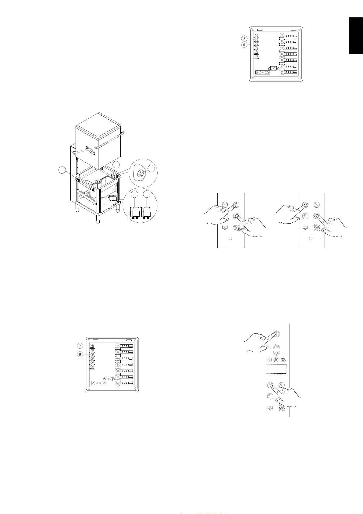
Connections for automatic detergent dispenser
(Figure 19)
dispensers”).
Figure 21 Rinse aid dispenser terminal block
• Connect the rinse-aid dispenser between terminals 8 and 9. These connection points are live
during filling of the tank and at the end of the rinse
cycle for a set time (see paragraph G4 “Setting the
dispensers”).
MANUAL ACTIVATION
Whenever the detergent containers are replaced, it
may be necessary to activate the dispensers manually
in order to fill the hoses and eliminate any air. Simultaneously press the buttons, as shown in the figures
below. If necessary, repeat this operation several
times.
Figure 19 Automatic dispenser arrangement
There are two holes (plugged) “O” (Ø 5mm) for introducing the detergent. These holes may be easily identified from outside by looking for the countersunk marks
on the external panel.
Inside the tank there is a hole “P” (Ø 10 mm) closed
with a plug, which may be used for mounting a liquid
detergent injector.
Electrical connections for automatic detergent and
rinse-aid dispensers.
Terminals are available on the power supply terminal
board for the electrical connection of external dispensers working at 220-240 V. Max. power 30 VA.
Figure 20 Detergent dispenser terminal block
DETERGENT DISPENSER RINSE-AID DISPENSER
G4 Setting the dispensers
All operations should be carried out with the appliance
switched on, the hood open and no cycle selected
.
Press the On/Off button ("A" - Ta b le 2 "Control panel")
and Wash cycle 1 button ("G" - Ta bl e 2 "Control panel")
together for 5 seconds, to access the programming
mode and the display shows the parameter "".
• Connect the detergent dispenser between terminals 7 and 9. These connection points are live for a
set time during filling of the tank and at the start of
the wash cycle (see paragraph G4 “Setting the
27
Page 26
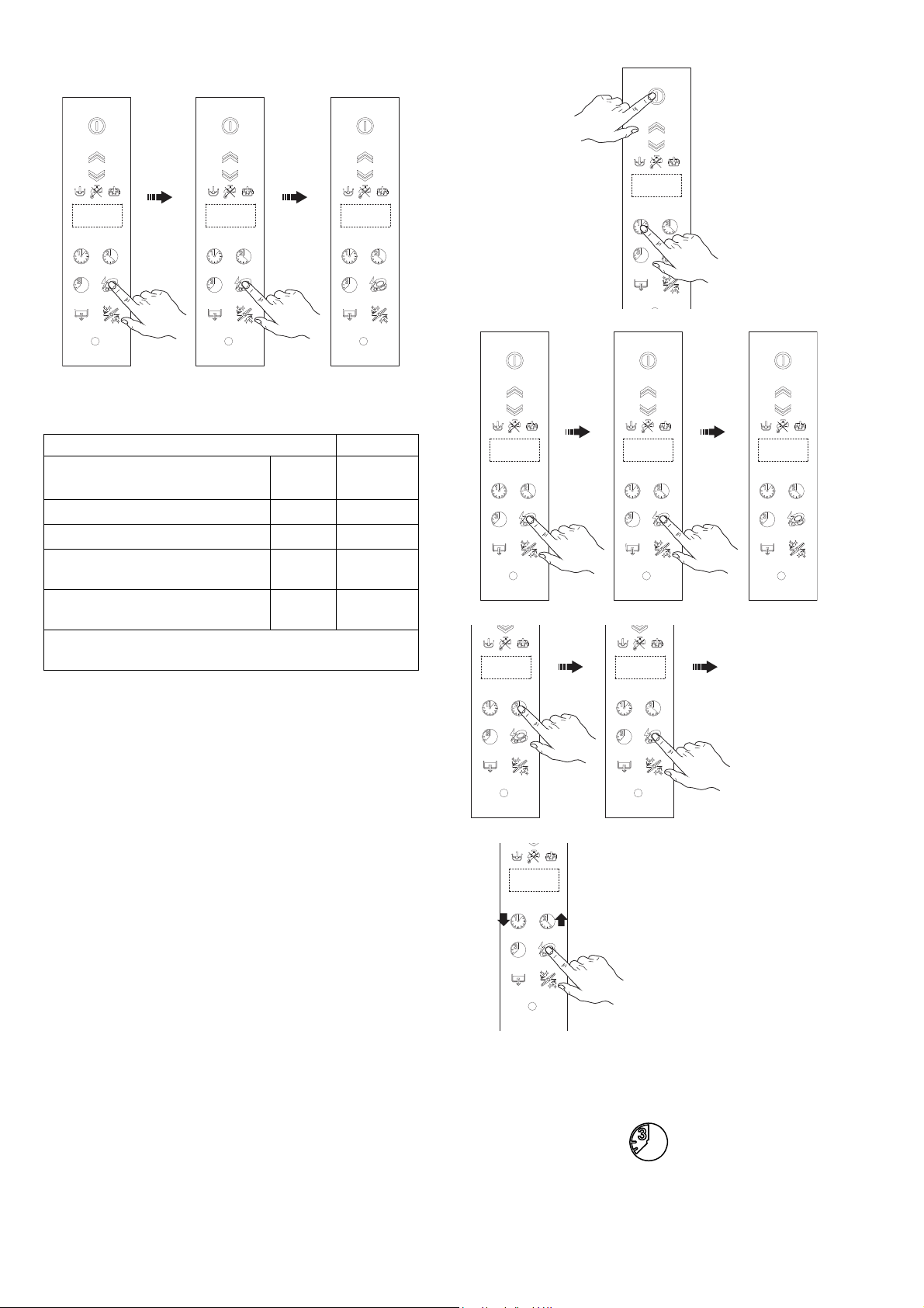
Press the button ("L" - Ta b le 2 "Control panel") twice to
USr
-
+
access the detergent and rinse aid adjustment parameters.
The display shows which is the first parameter of
the dispenser family:
Parameter description
Unit of measure of dispensers
(= g/l or = seconds)
Initial amount of detergent
Initial amount of rinse-aid
Amount of detergent during
the cycle
Amount of rinse-aid during the
cycle
(*) The values given in the table refer to the factory-
settings.
Value (*)
2,00 g/l
0,12 g/l
2,00 g/l
0,12 g/l
• access the programming mode
• access the dispenser family
• Select the parameter
1. Use the Wash cycle 1 ("G" - Table 2 Control panel)
and Wash cycle 2 ("H" - Table 2 Control panel) buttons to select the parameter to modify.
2. Press the button ("L" - Table 2 Control panel) to
modify the parameter value.
3. Press the Wash cycle 1 ("G" - Table 2 Control
panel) and Wash cycle 2 ("H" - Table 2 Control
panel) buttons respectively to decrease/increase
the value.
4. Press the button ("L" - Table 2 Control panel) to
store the set value and return to parameter selection (see point 1).
For example, to adjust the parameter , proceed
as follows:
• modify the parameter value
Press the button ("L" - Table 2 Control panel) to store
the set value.
To exit the programming mode, press the Wash cycle 3
button (“I” - Table 2 “Control panel”).
28
Page 27

ENGLISH
External dispenser adjustment
IMPORTANT
With external dispensers, it may be more useful to
have the parameters expressed in seconds, setting the
parameter to =seconds. In this way the
value of the parameters represents the duration in
seconds.
Listed below are special values usable when external
automatic dispensers are connected to the equipment:
-if the detergent dispenser only
operates during wash pump operation; terminals
7-9 of the main terminal board are powered at the
same time.
-if the detergent dispenser only
operates during filling electrovalve operation for
restoring the boiler level; terminals 7-9 of the main
terminal board are powered at the same time.
-if the rinse-aid dispenser only
operates during filling electrovalve operation for
restoring the boiler level; terminals 8-9 of the main
terminal board are powered at the same time.
-if the rinse-aid dispenser only operates
during wash pump operation; terminals 8-9 of the
main terminal board are powered at the same time.
For connections, see the wiring diagram.
The mixing of different types of detergent/rinse-aid
will cause crystallisation, which may result in a
breakdown of the dosing pump. Failure to observe
this condition will invalidate the guarantee and
product liability.
Example 1:
Supposing that an external detergent dispenser has
been connected with a tank concentration measuring
sensor, a standard setting could be as follows:
•
the parameter value is in seconds.
• the dispenser is not activated during fill-
ing of the tank.
• the dispenser is activated during
wash pump operation and, according to the concentration of detergent detected by the sensor, the
correct amount of detergent is dispensed.
Example 2:
Supposing that an external rinse-aid dispenser has
been connected with a tank concentration measuring
sensor, a standard setting could be as follows:
• the parameter value is in seconds.
• the dispenser is activated at each wash
cycle simultaneously with operation of the filling
solenoid valve. In this way avoiding modifications to
the wiring of the machine.
Suggestion: to check the effectiveness of the rinseaid, look at freshly washed glasses against the light.
Drops of water remaining on the glass indicate an
insufficient amount while streaks indicate an excess.
Changing the detergent/rinse-aid type.
If changing to a different detergent/rinse-aid type
(even one by the same manufacturer), you must rinse
the suction and pressure hoses with fresh water before
connecting the new detergent/rinse-aid container.
29
Page 28
H GENERAL SAFETY RULES
H1 Introduction
The machines are provided with electric and/or
mechanical safety devices for protecting workers and
the machine itself. Therefore the user must not remove
or tamper with such devices.
The Manufacturer declines any liability for damage due
to tampering or their non-use.
H1.1 Protection devices installed on the machine
H1.1.1 Guards
The guards on the machine are:
- fixed guards (e.g. casings, covers, side panelling,
etc.), fixed to the machine and/or frame with screws
or quick-release couplings that can only be
removed or opened with tools;
- interlocked movable guards (front panels) for
access to inside the machine;
- access doors to the machine’s electrical equipment, made from hinged panels openable with
tools. The door must not be opened during machine
movement, if inside the door there is equipment
that is hazardous when live or under pressure.
IMPORTANT!
Several illustrations in the manual rep-
resent the machine, or parts of it, without guards or with guards removed.
This is purely for explanatory requirements. Never operate the machine
without the guards or with the safety
devices deactivated.
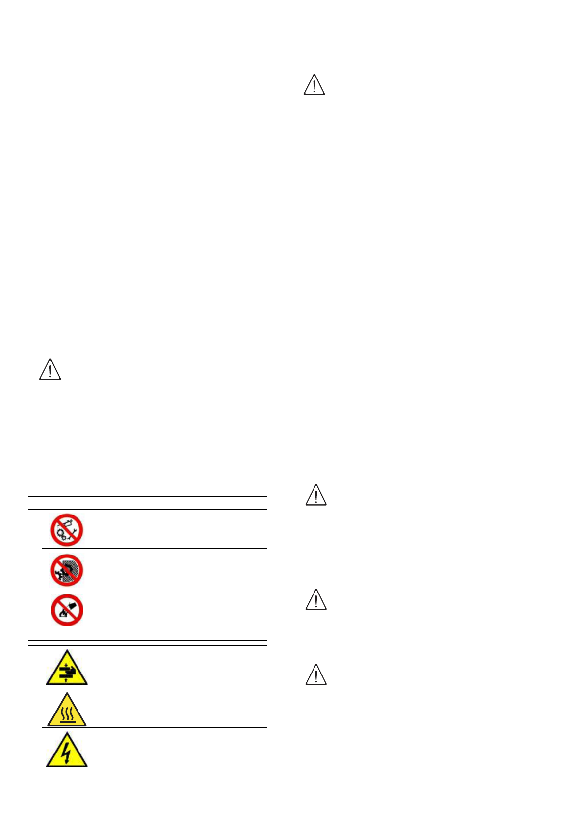
H1.2 Safety signs to be displayed on the
machine or near the work area
MEANING
P
R
O
H
I
B
I
T
I
O
N
D
A
N
G
E
R
Do not oil, lubricate, repair and
adjust moving parts.
Do not remove the safety devices.
Do not use water to extinguish fires
(shown on electrical parts).
DANGER OF CRUSHING HANDS
DANGER OF BURNS
DANGER OF ELECTROCUTION
(shown on electrical parts with indi-
cation of voltage).
WARNING!
Do not remove, tamper with or make
the labels on the machine illegible.
H2 Decommissioning
When the machine is no longer to be used, make it
unusable by removing the feed wiring from the power
supply and the water connections.
H3 Instructions for use and maintenance
Risks mainly of a mechanical, thermal and electrical
nature are present in the machine.
Where possible the risks have been neutralized:
• directly, by means of adequate design solutions,
• or indirectly by using guards, protection and safety
devices.
Any anomalous situations are signalled on the control
panel display.
During maintenance several risks remain, as these
could not be eliminated and which must be neutralized
through specific behaviour and precautions.
Do not carry out any control, cleaning, repair or maintenance operations on moving parts.
Workers must be informed of the prohibition by means
of clearly visible signs.
To guarantee machine efficiency and correct operation, periodical maintenance must be carried out
according to the instructions given in this manual.
In particular, make sure to periodically check correct
operation of all the safety devices and the insulation of
electrical cables, which must be replaced if damaged.
IMPORTANT!
Machine maintenance operations must
only be carried out by specialized
Technicians provided with all necessary personal protection equipment
(safety shoes, gloves, glasses, overalls, etc.), tools, utensils and suitable
ancillary means.
WARNING!
Never operate the machine by remov-
ing, modifying or tampering with the
guards and protection or safety
devices.
IMPORTANT!
Before carrying out any operation on
the machine, always consult the manual which gives the correct procedures
and contains important information on
safety.
30
Page 29

ENGLISH
H4 Improper use
Improper use is any use differing from that specified in
this manual. During machine operation, other types of
work or activities considered improper and that in general can involve risks for the safety of operators and
damage to the system are not allowed.
Improper use includes:
• failure to disconnect the power supply with the main
switch in “O” off position before carrying out adjustment, cleaning, resetting and maintenance operations;
• failure to disconnect the power supply with the main
switch in off position “O” at the end of the day;
• lack of machine maintenance, cleaning and periodical checks;
• structural changes or modifications to the operating
logic;
• tampering with the guards or safety devices;
• failure to use personal protection equipment by
operators, specialized technicians and maintenance personnel;
• failure to use suitable accessories (e.g. use of
equipment, ladders, etc., unsuitable for carrying out
maintenance on equipment positioned inside the
machine);
• keeping combustible or flammable materials, or in
any case materials not compatible with or pertinent
to the work, near the machine;
• incorrect machine installation (see chapter E
“Installation and assembly”);
• placing in the machine any objects or things not
compatible with washing or that can obstruct/damage the machine or persons or pollute the environment;
• non-compliance with the requirements for correct
machine use;
• other actions that can cause risks not eliminable by
the Manufacturer.
RESIDUAL
RISK
Slipping or
falling
[ U - M ]
Burns
[ U - M - P ]
Electrocution
[ M ]
Falling from
above
[ I - U - M ]
Tipping of
loads
[ I - M ]
Chemical
[ I - U - M - P ]
Crushing or
shearing
[ I - U - M ]
DESCRIPTION OF HAZARDOUS SITUATION
The operator can slip due to water or dirt
on the floor.
The operator deliberately or unintentionally touches some components inside the
machine or dishes at the outfeed without
using gloves or without allowing them to
cool.
Contact with live parts during maintenance operations carried out with the
electrical panel powered. The operator
intervenes (with a power tool or without
disconnecting the power to the machine)
lying down on the wet floor.
The operator intervenes on the machine
using unsuitable systems to access the
upper part (e.g. rung ladders, or climbs
on it).
During maintenance on the machine or
the packing containing the machine with
the use of unsuitable accessories or lifting systems or with load unbalanced.
Contact with chemical substances (e.g.
detergent, rinse aid, scale remover, etc.)
without taking adequate safety precautions. Therefore always refer to the safety
cards and labels on the products used.
Possible risk of injury to upper limbs
during the hood closing operation.
Table 3 Residual risks
H5 Residual risks
The machine has several risks that were not completely eliminated from a design standpoint or with the
installation of adequate protection devices.
Nevertheless, through this manual the Manufacturer
has taken steps to inform operators of such risks, carefully indicating the personal protection equipment to be
used by them.
Sufficient spaces are provided for during the machine
installation phases in order to limit these risks.
To preserve these conditions, the corridors and areas
around the machine must always be:
• kept free of obstacles (e.g. ladders, tools, containers, boxes, etc.);
• clean and dry;
• well lit.
For the Customer’s complete information, the residual
risks remaining on the machine are given below; such
actions are to be considered incorrect and therefore
strictly forbidden.
APPLICATION PHASE: I=Installation, U=Normal use,
M=Maintenance, P=Cleaning.
31
Page 30

I NORMAL MACHINE USE
IMPORTANT
I1 Correct use
Our appliances are designed and optimized in order to
obtain high performance and efficiency. This equipment must only be used for its expressly designed purpose, i.e. washing dishes with water and specific
detergents. Any other use is to be deemed improper.
I2 Characteristics of personnel enabled to
operate on the machine
Operator qualified for normal use must have at least:
• knowledge of the technology and specific experience in operating the machine;
• adequate general basic education and technical
knowledge for reading and understanding the contents of the manual,
• the capacity for a correct interpretation of the drawings, signs and pictograms;
• sufficient technical knowledge for safely performing
his duties as specified in the manual;
• knowledge of the regulations on work hygiene and
safety.
In the event of a significant anomaly (e.g. short circuits,
wires coming out of the terminal block, motor breakdowns, worn electrical cable sheathing, etc.) the operator qualified for normal machine use must:
• immediately deactivate the machine by turning the
main switch to “O” ;
• close the machine water supply by shutting off the
water.
I3 First use
Carry out a couple of cycles without dishes to flush out
any industrial grease which has remained in the tank
and piping.
The button "A" lights up (Tab le 2 "Control panel"), indicating that the dishwasher is powered and that water is
being introduced and heated.
The word “FILL” is shown on the display during the
entire filling and heating stage:
fIL
Warning, this dishwasher does the first tank filling
through several consecutive hot rinse cycles, while the
display shows the message FILL (flowing).
This system let save up to 30% of time than traditional
models.
If the hood is opened during this stage the message
"CLOSE" will appear on the display:
CLO
The filling and heating stage has finished when the
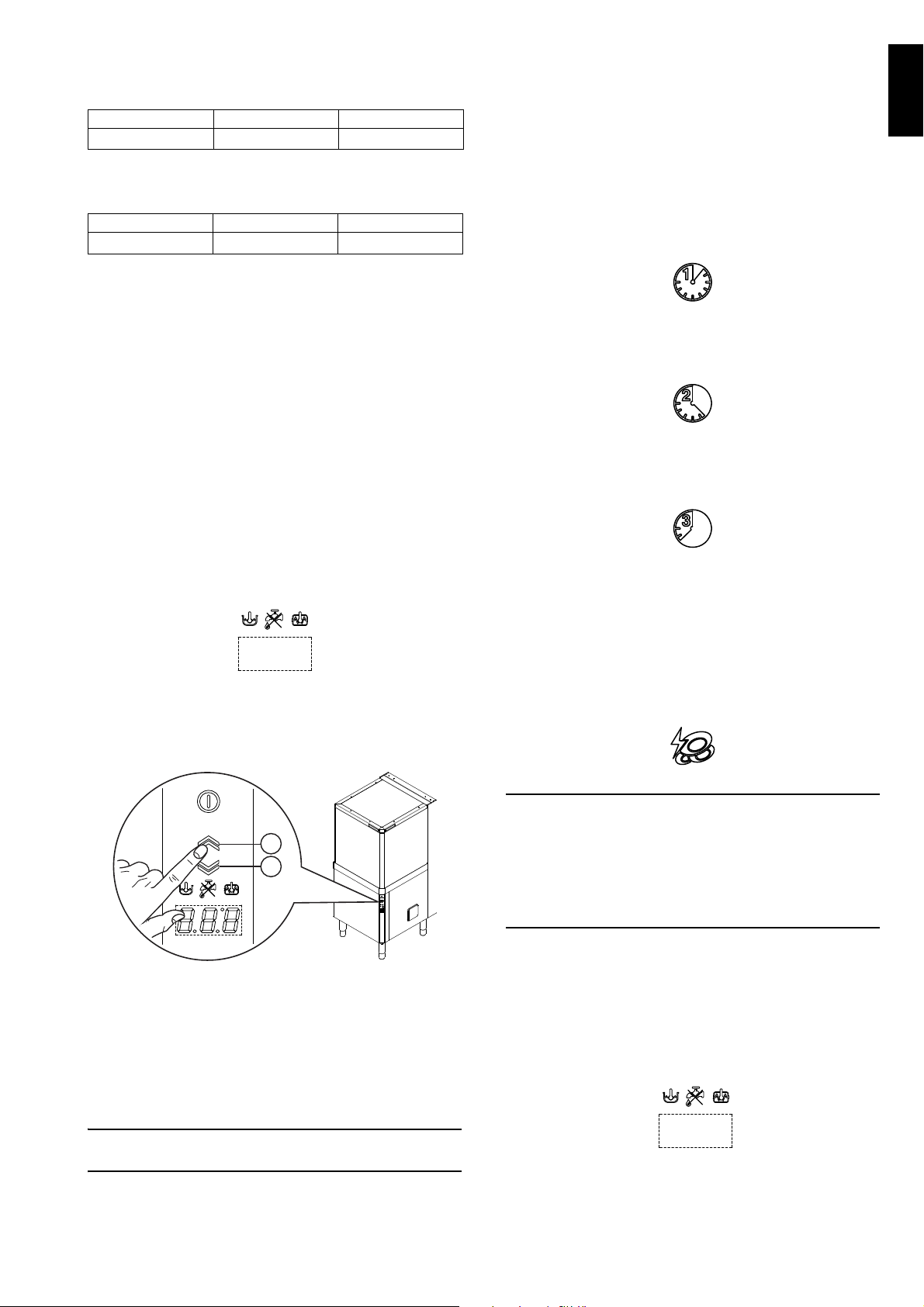
display shows the tank temperature:
55°C
To display the boiler temperature during heating of the
tank, leave the hood and press the button “G” (Tabl e 2
“Control panel”).
I4 Daily activation of machine
• Make sure the filters, arms and the overflow are
correctly fitted according to that indicated in par.
G1.2 “Check the positioning of tank components”
and E8 “Energy control arrangement”.
• Open the water supply cocks.
• Activate the main switch by turning it to position “I”.
• Switch on the dishwasher by pressing the button “A”.
• Raise the hood (with an automatic appliance, by
pressing the open/close button “B/C” - Ta b l e 2
“Control panel”) and check that all the components
are in their correct position.
• Close the hood (with an automatic appliance, by
pressing the open/close button “B/C” - Ta b l e 2
“Control panel”).
32
If the indicator "E" (see Table 2 "Control panel")
lights up, check that the water cock is open (see
par. I7 Allarms).
I5 Wash cycles
The wash cycle includes a wash with hot water and
detergent at a temperature of at least 55°C/ 131°F
(min. 66°C /150°F for Marine USPH versions) and a
rinse with hot water and rinse aid (min. 82°C / min.
180°F).
This machine can operate in 2 modes, "High Productivity" and "ETL-Sanitization". When the machine is set
in "High Productivity" mode, the parameters that define
the cycle times and temperature set points are the
standard parameters, whereas when the machine is
set in "ETL-Sanitization" mode, the parameters are
such as to ensure the "ETL-Sanitization" test (see
times table).
Page 31
ENGLISH
Table o f times
IMPORTANT
B
C
End
Standard cycle time with supply water
ductivity" mode (factory default setting):
I II III
45 (***)
84 150
in "high pro-
• Pre-wash the dishes by spraying them with cold or
lukewarm water, without using any detergent.
• Insert the rack containing the dirty dishes.
• Close the hood and select the suitable wash cycle;
the corresponding indicator light comes on and the
wash cycle starts.
Standard cycle time with supply water
tion mode:
I II III
57 (***)
(***) With supply water temperature at 65°C/ 149°F.
In models with energy saving device (ESD) cycle
duration is extended by 11 seconds.
A device lengthens the cycle time if the water in the
boiler has not reached the minimum temperature for
correct rinsing.
The cycle times and the temperature may be
personalised (e.g. increase of the rinse time and
temperature).
The cycle times should only be set by a specialised
technician.
I6 Operation
The filling and heating stage has finished when the
display shows the tank temperature:
84 150
in ETL-Sanitiza-
55°C
The appliance is then ready for use:
• Leave the hood.
With automatic machines, press the button "B" to
open the hood and button "C" (Figure 22) to close it.
Usable wash cycles:
- Cycle I
For lightly soiled dishes: press button “G” (see Tabl e 2
“Control panel” and table of times).
- Cycle II (recommended)
For normally dirty dishes: press button “H”(see Table 2
“Control panel” and table of times).
- Cycle III
For very dirty dishes: press button “I” (see Tabl e 2
“Control panel” and table of times).
- High Productivity or ETL-Sanitization mode
Press and hold down (5 sec.) the button "L" (see
Tab l e 2 "Control panel") to switch the machine from
"High Productivity" mode to "ETL-Sanitization" mode
and vice versa. The button "L " is off when the machine
is set in "ETL-Sanitization" mode and lights up when
the button is pressed and the machine is configured in
"High Productivity" mode (factory default setting).
Figure 22 Automatic hood opening/closing
• Pour the required amount of detergent non-foaming
into the tank (in models without automatic
dispenser).
• Arrange dishes in the rack, avoiding washing
decorated dishes, silverware in contact with other
metals and the drying of food residuals on dishes.
Remove large food scraps from the dishes to prevent clogging the filters.
Only for models with incorporated water softener
If the salt container is empty, the message
is displayed at the start or end of the cycle.
Place the salt in the special container, following the
instructions given in the section "Undercounter dishwasher with incorporated continuous water softener”.
• To stop the wash cycle, just press the selected cycle
button or leave the hood.
• To continue the wash cycle, just press the selected
cycle button or close the hood. The cycle starts again
from where it stopped.
•
At the end of the wash, the dishwasher emits a series
of beeps and “END” blinks on the display:
lift the hood and remove the rack containing the clean
dishes.
33
Page 32
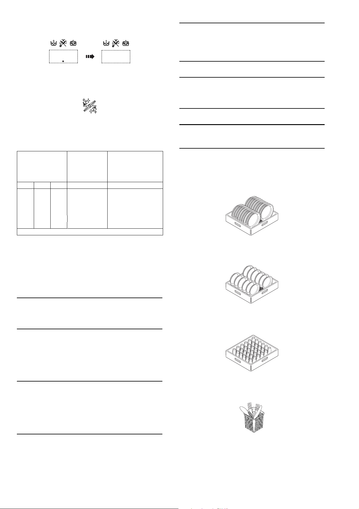
In models with energy saving device (ESD), before the
IMPORTANT
IMPORTANT
IMPORTANT
IMPORTANT
IMPORTANT
3...... ...2
End
message "END", the display shows a countdown for a
few seconds:
With automatic machines, the hood opens automatically at the end of the wash cycle.
- Delime cycle (if enabled)
Press the button "N" (see Ta bl e 2 Control panel)
to run a machine water circuit delime cycle with
vinegar.
It is advisable to run this cycle according to that given
in the table:
The Delime
cycle should
Water hardness
°f °d °e Cycles Days
5 2,8 3,5 1500 50
10 5,6 7,0 750 25
15 8,4 10,5 510 17
20 11,2 14 380 13
25 14 17,5 300 10
30 16,8 21,1 250 8
(*) Considering a rinse time according to the factory settings.
be run
approxima
tely every (*):
Using cycle 2 for 30
cycles/day,
Delime cycle should
be run approximately
every (*):
the
Proceed as follows:
•
Insert the Delime tube present in the machine,
identified by an appropriate label, in a container
with at least 2l of wine vinegar 6% (2l is the minimum amount of vinegar needed for a correct
Delime cycle)
.
The appliance will not remove burnt food deposits
from dishes. Dishes with burnt-on food deposits
should be cleaned mechanically/chemically (for
example, pre-wash under running water) before
putting them in the dishwasher.
The use of “foaming”/non-specific detergents or in
any case detergents used in different ways from that
prescribed by the manufacturer, can cause damage
to the dishwasher and compromise washing results.
Failure to remove the residuals of detergent possibly
used for manual prewash can cause malfunctioning
of the dishwasher and compromise washing results.
Change the water in the tank at least once a day.
Type of racks and loading
• YELLOW rack: for 18 plates with maximum diameter of 240 mm.
Figure 23 YELLOW rack
• GREEN rack: for 12 bowls with maximum diameter
of 240 mm.
Only use wine vinegar (with 6% of acetic acid) and not
other descaling substances. Descaling with the use of
chemical substances other than vinegar must only be
done by a specialized technician.
• Remove the basket with dishes and remove the overflow "2" (see Figure 17 Filters and overflow).
• Close the hood.
• Activate the delime cycle by pressing the button "N"
(see Ta bl e 2 Control panel) for at least 5 seconds.
The delime cycle lasts about 1h 30sec; during this
phase the hood must not be opened and no other
command can be activated until completion of the
cycle in progress. If the machine is turned off
during the delime cycle, at the next restart the
cycle will resume exactly from where it was interrupted, until its completion.
• At the end of Delime cycle, the dishwasher sounds a
series of beeps and "END" will flash on the display.
• Refit the previously removed overflow.
Figure 24 GREEN rack
• BLUE rack for glasses: the glasses should be placed upside down.
Figure 25 BLUE rack for glasses
• YELLOW container for cutlery: insert 15 items, with
the handles pointing downwards, in each container.
Figure 26 YELLOW container for cutlery
Available as accessories: dividers for glasses and rack
for dishes with maximum diameter of 320 mm.
34
Page 33
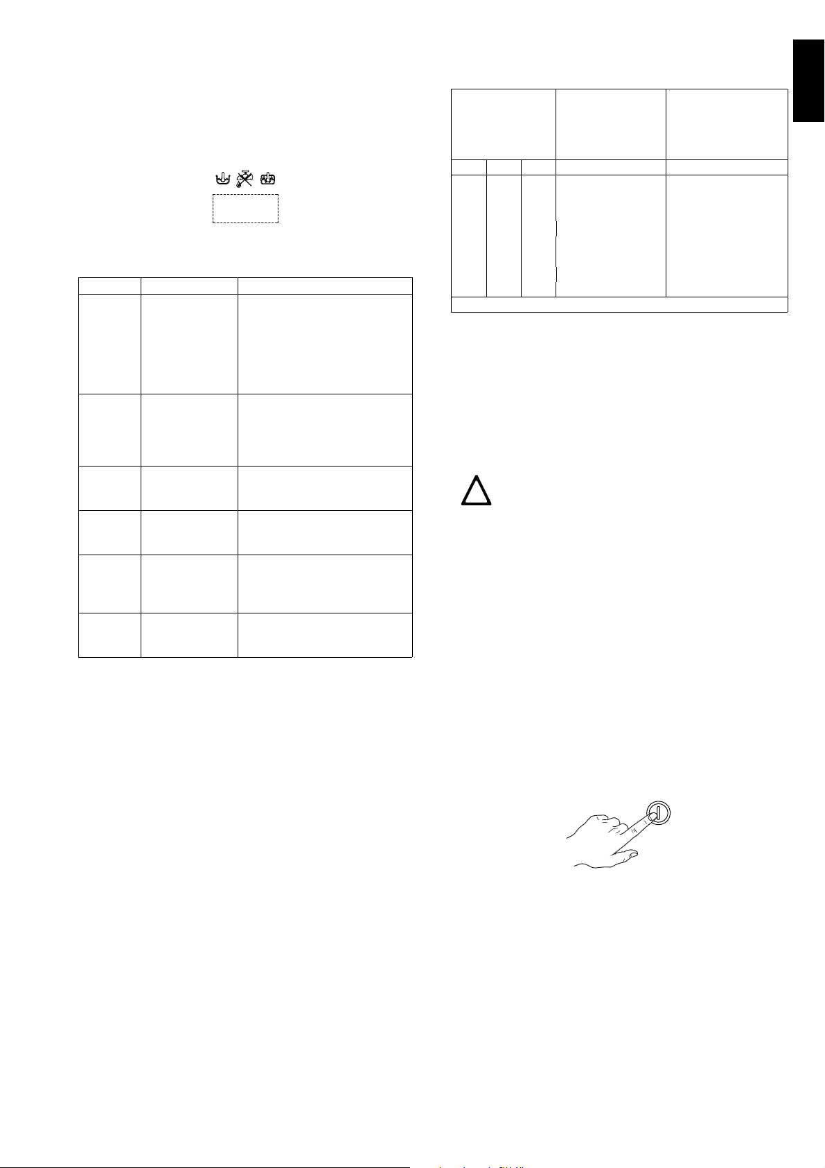
ENGLISH
Note: if only one type of dish rack is to be used, it is
!
advisable to choose the GREEN rack.
I7 Alarms
In case of a generic dishwasher fault, the display
shows the relevant alarm code.
For example:
A 1
List of possible documented machine alarms with
respective cause / cure.
Code Description Cause / Solution
A1 (*) NO WATER Check that the cock is open.
Check that the water inlet filter is
clean.
Check the minimum mains
pressure.
Check that the overflow pipe is
inserted.
B1 INEFFICIENT
DRAINAGE
B2
C1..C9 CALL THE
E1..E8 CALL THE
F21..F22 CALL THE
TANK WATER
LEVEL TOO
HIGH
SERVICE
CENTRE
SERVICE
CENTRE
SERVICE
CENTRE
(*) When the display shows alarm A1, the "water
tap" indicator also lights up ("E" - Tab l e 2 "Control
panel").
I8 Hood type dishwasher with incorporated
continuous water softener
These models have a continuous softener in the
dishwasher water circuit. By means of special resins,
this device removes the calcareous substances from
the feed water, supplying decalcified water for
washing.
For the continuous softener to work properly the resins
must be regenerated periodically, with frequency
depending on the hardness of the water and the number of wash cycles carried out.
Unlike conventional water softeners, this continuous
softener does not require machine stops for regenerating the resins.
Check if the overflow has been
removed.
Check for obstruction on the
waste outlet pipe and the
overflow aperture.
Check for obstruction on the
waste outlet pipe and the
overflow aperture.
The appliance continues to
operate, but appropriate checks
by a technician are
recommended.
AUTONOMY OF THE FULL SALT CONTAINER
ACCORDING TO THE CHANGE IN INLET WATER
HARDNESS
The salt container
must be filled
Water hardness
°f °d °e Cycles Days
15 8,4 10,6 2700 90
20 11,2 14 2180 73
25 14 17,6 1575 53
30 16,9 21,1 1035 35
35 19,7 24,6 855 30
40 22,5 28,1 675 23
45 25,2 31,6 450 15
50 28,1 35,1 270 9
(*) Considering a rinse time according to the factory settings.
approximately
every (*):
Using cycle 2 for 30
cycles/day, the salt
container must be fil
led approximately
every (*):
-
Salt container
The water can only be softened if there is salt in the
special container. The salt container must be filled
when the dishwasher is started the first time and
whenever the message
appears and an
audible alarm sounds.
No salt in the container
IMPORTANT:
Only use coarse salt with a purity level of
99.8% NaCl. The use of salt with a lower
purity level can cause clogging of the salt
container filter and malfunctioning of the
water softener.
When the salt container is empty, the message
appears on the display and an audible alarm
sounds. Wash cycles can be started just the same,
even if the display signals no salt; in which case the
water used for washing is not softened.
How to fill the salt container
• Raise the hood (with an automatic appliance, by
pressing the open/close button “B/C” - Ta b l e 2
“Control panel”).
• Switch off the dishwasher by pressing button “A”
(Tab le 2 “Control panel”).
• Unscrew cap "A" (Figure 27) of the salt container,
turning it anticlockwise.
35
Page 34
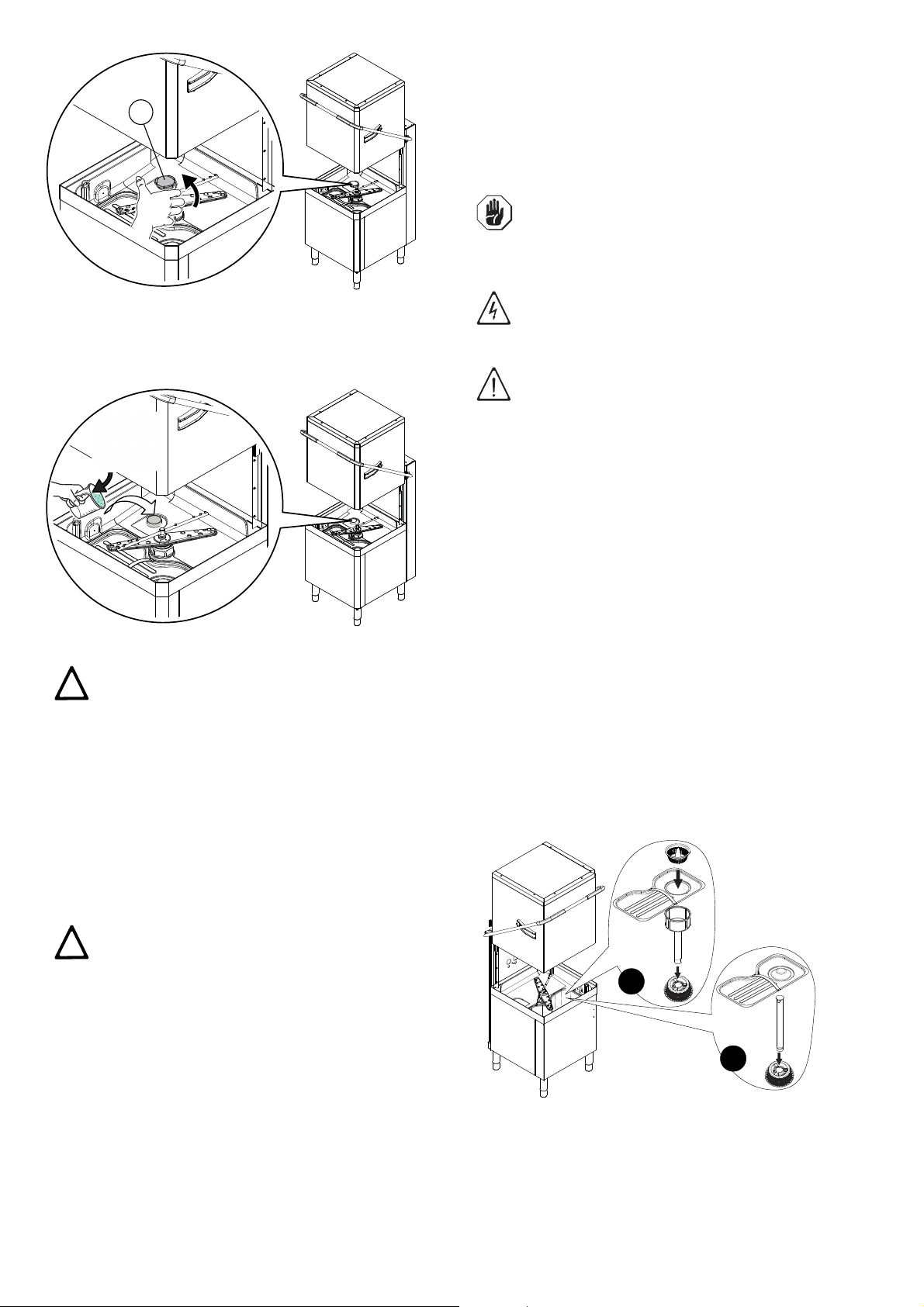
instructions and observe the safety rules given in the
A
NaCl
(2 kg)
!
!
1
B
2
3
3
4
2
1
A
information cards provided with the product or substance.
In order to reduce the environmental impact of pollutant substances, clean the equipment (externally and
internally where necessary) with products that are
more than 90% biodegradable.
CAUTION!
Do not use steel wool or similar mate-
rial to clean s/steel surfaces. Do not
use detergents containing chlorine.
Figure 27 Unscrew the salt container cap
•
Pour approx. 1.5 kg of coarse salt [NaCl] in container
"A" (an amount sufficient to fill the salt container up to
the rim) using the special funnel supplied (Figure 28)
Figure 28 Add the salt
IMPORTANT:
Only salt may be placed in the salt con-
tainer. Do not introduce any other chemical
substances such as detergent, rinse aid or
descaling agent, since these would inevitably damage the appliance. Such damage
invalidates any warranty and relieves the
manufacturer of all liability.
• Remove any traces of salt from the filling hole and
the container thread of the closing cap.
• Refit the cap of container "A", turning it clockwise
and making sure it is tight.
.
IMPORTANT!
Do not clean the machine with jets of
water.
CAUTION!
Contact with chemical substances (e.g.
detergent, rinse aid, scale remover,
etc.) without taking appropriate safety
precautions (e.g. personal protection
equipment) can involve exposure to
chemical risk and possible damage to
health. Therefore always refer to the
safety cards and labels on the products
used.
I9.1 End of service and daily internal cleaning
The appliance is designed to carry out an automatic
cleaning cycle to help flush out any residues and to
guarantee greater health and hygiene:
• Lift the hood and take out the rack containing the
clean dishes.
• In versions with supplementary filtering system
(FS), remove the basket filter "1", the flat filter "2",
the tank filter "3" and the pump suction filter "4" (“A”
-
Figure 29).
• In versions without supplementary filtering system
(FS), remove the flat filter "1", the overflow "2" and
the pump suction filter "3" (“B” - Figure 29).
.
IMPORTANT:
The message
several wash cycles even after topping-
up the salt, as the salt must circulate in
the entire system. Correct operation of
the dishwasher is not, however, affected.
The salt container always has water in it, therefore it is
normal if water comes out during filling
may appear for
.
I9 Machine cleaning
Cleaning must be carried out after every day of use.
Use hot water, a neutral detergent/detersive if necessary, and a soft brush or sponge. If another type of
detergent is used carefully follow the manufacturer’s
36
Figure 29 Filters and overflow
• Close the hood.
• Select the drain cycle by pressing button “M”
(Ta b l e 2 “Control panel”).
Page 35
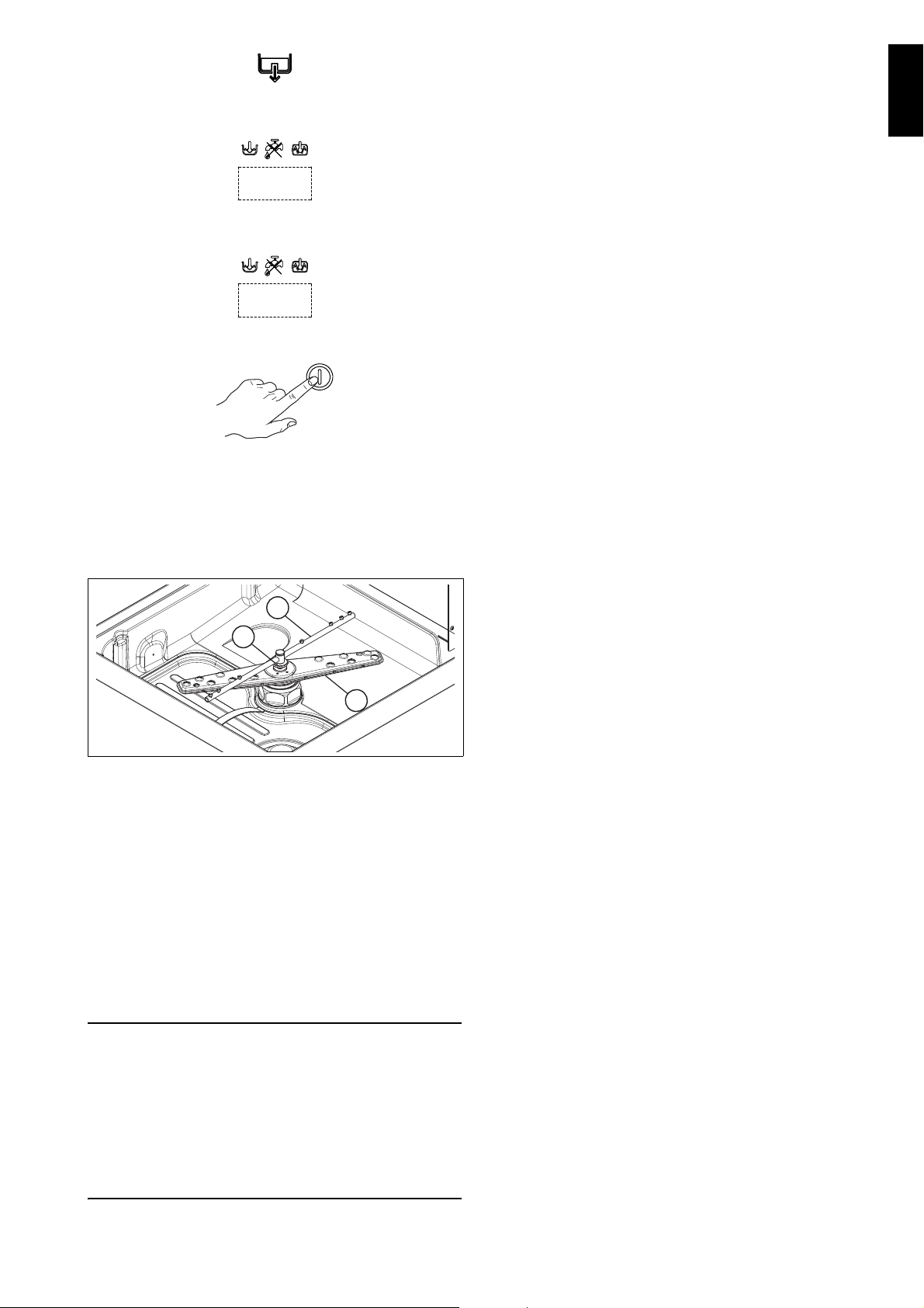
ENGLISH
The message "CLE" ("CLEAN") will be displayed
IMPORTANT
End
H
I
F
throughout the drain cycle:
To reduce the emission of pollutants into the environment, clean the appliance (externally and where
necessary internally) with products having a biodegradability of over 90%.
Leave the hood raised whenever the appliance is not in
use.
CLE
• After a few minutes, 3 beeps indicate the end of
thecleaning cycle and “END” blinks on the display:
• Switch off the dishwasher by pressing button “A”
(Ta b l e 2 “Control panel”).
• Switch off at the mains.
• Close the water supply cock.
• Replace the filter and the overflow.
Cleaning the nozzle jets
• Remove the upper and lower wash arms "F" and
rinse arms "I", undoing the ring nut "H" (Figure 30).
Figure 30 Wash and rinse arms
• Carefully clean the washing and rinse jets and
clean everything with hot water and neutral detergent/detersive, if necessary using a soft brush or
sponge. Do not use sharp implements to clean the
nozzle holes, which could otherwise be damaged.
Upon completion of cleaning operations, replace the
parts removed previously.
I9.2 Exterior cleaning
Before carrying out any cleaning operations, turn off
the power at the mains.
Clean the stainless steel surfaces using warm
soapy water; never use detergents containing
abrasive substances nor steel scrapers, common
wire wool, brushes or scrapers; rinse thoroughly
using a wet cloth and carefully wipe dry.
Clean the control panel using a soft damp cloth
and a neutral detergent if necessary.
Do not wash the appliance using direct or highpressure water jets.
I10 Long idle periods
Whenever the dishwasher is not going to be used for a
long period of time (e.g. one month), carefully carry out
the following instructions.
• Close the water supply cock.
• Completely drain the tank.
• Remove and carefully clean the filters.
• Completely drain the incorporated dispenser
hoses, removing them from the containers. Repeat
the procedure described in the paragraph “Manual
activation” at least 3 times.
• Completely drain the boiler.
• Clean the inside and outside of the machine as
indicated in par. I9.1 “End of service and daily internal cleaning” and I9.2 “Exterior cleaning”.
• Spread a film of paraffin oil over the steel surfaces.
When using the machine again, follow the indications
in par. I4 “Daily activation of machine”.
I11 Maintenance
Inspection and maintenance intervals depend on the
actual machine operating conditions (total wash hours)
and ambient conditions (presence of dust, damp, etc.),
therefore precise time intervals cannot be given. In any
case, to minimize interruptions of the service, careful
and periodical machine maintenance is advisable.
Therefore, it is advisable to:
• Descale the boiler, inside surfaces of the tank and
the machine piping once or twice a year (call technical assistance).
• Every month descale the wash and rinse jets with
vinegar or scale remover.
• The internal hose of the rinse-aid and detergent
peristaltic dispenser should undergo periodic maintenance (once or twice a year).
• If present, clean the finned coil of the energy saving
device once or twice a year (call technical assistance).
It is also advisable to stipulate a scheduled preventive maintenance contract with technical assistance.
I11.1 Preventive maintenance
The preventive maintenance call can be activated (call
technical assistance).
On reaching the set number of cycles (e.g. 20000), a
technical assistance call message appears on the display.
This message suggests calling a specialized technician, for a general check of the equipment.
37
Page 36

I12 Machine disposal
At the end of the product’s life cycle, make sure the
equipment is not dispersed in the environment. The
equipment must be disposed of in compliance with
current regulations in the country of use.
All metal parts are in s/steel (AISI 304) and removable.
Plastic parts are marked with the letters of the material.
The symbol on the product indicates that this
product should not be treated as domestic waste, but
must be correctly disposed of in order to prevent possible negative consequences for the environment and
the human health.
Regarding the recycling of this product, please contact
the sales agent or dealer of your product, your aftersales service or the appropriate waste disposal service.
I13 Troubleshooting
DISHWASHER DOES NOT WASH WELL
1. Check if the suction filter is dirty and clean it thoroughly.
2. Check if the wash jets are clogged by solid food
remains.
3. Check that the initial amount of detergent or subsequent additions are correct.
4. The selected wash cycle is too short. Repeat the cycle.
5. Check that the tank temperature is at least 55°C /
131°F.
6. Check that the dishes are stacked correctly in the racks.
GLASSES AND DISHES ARE NOT DRIED PROPERLY
1. Check that there is rinse-aid in the container and if necessary top up.
2. Check the set amount of rinse-aid (see “setting the
dispensers” paragraph).
3. Check that the water temperature is between 80°C and
90°C.
CONDENSATION ON GLASSES
1. Check that there is rinse-aid in the container and if necessary top up.
2. Check the set amount of rinse-aid (see “setting the
dispensers” paragraph).
3. Remove the rack of glasses immediately the cycle has
ended.
STAINS ON THE GLASSES
1. Only use “non-foaming” products for professional
dishwashers.
EXCESSIVE FOAM IN THE TANK
1. Check that the wash water temperature is not less than
55°C / 131°F.
2. Check if the amount of product dispensed by the detergent dispenser is excessive (see “setting the dispensers” paragraph).
3. Ensure that the tank has not been cleaned with unsuitable cleaners. Drain the tank and rinse thoroughly
before new wash cycles.
4. If a foaming detergent has been used, drain and refill
the tank with water until the foam disappears.
SMEARS OR SPOTS ON THE GLASSES
1. Reduce the amount of rinse-aid (see “setting the
dispensers” paragraph).
THE WASH OR RINSE ARMS TURN SLOWLY
1. Remove and thoroughly clean the arms.
2. Clean the wash pump suction filter.
38
 Loading...