

Electrolux EFLS617SIW, EFLS517SIW, EFLS417SIW Technical & Service Manual
Technical Service Manual
Front Load Washing Machine
For Models EFLS617SIW / EFLS517SIW / EFLS417SIW
Publication #5995673125 May 2016

2

Table of Contents
1. Safety Information....................................................................................5
2. Purpose of this Manual........................................................................6
3. Warnings .....................................................................................................7
4. Product Features.....................................................................................8
4.1 EFLS617SIW / EFLS517SIW / EFLS417SIW.............................8
5. Model Specifications..............................................................................9
5.1 Electric Front Load Washers........................................................9
6. Technical Characteristics...................................................................12
6.1 Detergent Dispenser.....................................................................12
6.1.1 Detergent Dispenser with Multi-Way
Solenoid Valves.........................................................................12
6.1.2 Operating Principle of 4-Way Compartment
Conveyor.......................................................................................12
7. Electrical Characteristics....................................................................13
7.1 Electronic Control...........................................................................13
7.1.1 User Interface (UI) Board.......................................................13
7.1.2 Main Control Board.................................................................14
7.1.3 Motor Control Board - MCB................................................14
7.2 Schematic Diagrams -
EFLS617SIW / EFLS517SIW / EFLS417SIW.........................15
7.2.1 User Interface Board...............................................................15
7.2.2 Motor Control Board..............................................................15
7.2.3 Main Control Board................................................................16
7.3 Wiring Diagram -
EFLS617SIW / EFLS517SIW / EFLS417SIW........................17
8. Electrical Components –
EFLS617SIW / EFLS517SIW / EFLS417SIW.................................18
8.1 Pump...................................................................................................19
8.1.1 General Characteristics...........................................................19
8.2 Heating Element............................................................................19
8.2.1 General Characteristics..........................................................19
8.3 Temperature Probe (NTC)......................................................20
8.3.1 General Characteristics........................................................20
8.4 Analog Pressure Sensor...........................................................20
8.4.1 General Characteristics........................................................20
8.5 Door Lock........................................................................................21
8.5.1 General Characteristics.........................................................21
8.6 Three-Phase Asynchronous Motor – Inverter...............22
8.6.1 Motor Characteristics.............................................................22
8.7 Solenoid Valves............................................................................22
8.7.1 General Characteristics.........................................................22
8.7.2 Operating Principle................................................................22
8.7.3 Mechanical Jamming of the Solenoid Valve...............22
8.7.4 Low Water Pressure................................................................22
8.8 LED Drum Light............................................................................23
9. Top Panel Accessibility.......................................................................24
9.1 Main Control Board Assembly Accessibility....................24
9.2 Pressure Sensor Accessibility................................................24
9.3 Solenoid Valve Accessibility...................................................25
10. Rear Panel Accessibility...................................................................26
10.1 Belt....................................................................................................26
10.2 Heating Element Assembly
(Heater and NTC) Accessibility...........................................26
10.3 Motor Accessibility.....................................................................26
10.4 Motor Control Board Assembly Accessibility...............26
11. Door Lock Accessibility......................................................................27
12. Front Panel Accessibility..................................................................28
12.1 Control Panel Accessibility.....................................................28
12.2 Concentrated Wash Pump Accessibility..........................29
12.3 Drain Pump Accessibility........................................................29
12.4 Recirculation Pump Accessibility........................................29
12.5 Leveling Leg Accessibility.......................................................29
12.6 Drum Light Accessibility..........................................................29
13. Diagnostic System
- EFLS617SIW / EFLS517SIW / EFLS417SIW...........................30
13.1 Diagnostic Mode........................................................................30
13.2 Demo Mode.................................................................................32
13.3 Error Code Table........................................................................33
14. Troubleshooting Based on Error Codes.................................35
E11: Fill Time Too Long.......................................................................35
E13: Water Leak in Tub or in Pressure Sensor...........................37
E21: Water Not Pumping Out Fast Enough...............................38
E23: Drain TRIAC Error.......................................................................39
E24: Drain TRIAC Error Sensing.....................................................39
E31: Electronic Pressure Switch Error............................................40
E32: Pressure Sensor Calibration Problem................................40
E35: Pressure Sensor Indicates Water Overfill.........................41
E38: Air Trap Clogged........................................................................41
E41: Control Board Thinks the Door Switch is Open.............42
E42: Door Lock Device Failure.......................................................42
E43: Door Lock TRIAC Failure........................................................42
E44: Door Closed Sensing Failure................................................42
E45: Line Door Sensing Failure......................................................42
E57: High Current on Inverter..........................................................43
E58: High Current on Motor Phase..............................................43
E59: No Spin Signal for 3 Seconds..............................................44
E55: Under Speed...............................................................................44
E5A: High Temperature on Control Due to Overload..........46
E5B: Motor Control Under Voltage...............................................47
E5C: High Voltage Experienced by Motor Control...............47
E5D: Communication Problem with Motor Control...............48
E5E: Communication Problem from Motor Control...............48
E5F: Motor Control is Continuously Resetting.........................48
E62: Wash Temperature Too High.................................................49
E66: Heater Relay Problem.............................................................50
E68: Current Leakage to Ground on Heater or Wiring........50
E69: Heater Open...............................................................................50
E6A: Heater Relay Sensing Problem...........................................50
E71: Drum Water NTC Failure (Tub Heater)............................51
E74: Wash Temperature Does Not Increase.............................51
3

E84: Recirculation Pump TRIAC Series.......................................52
E85: Recirculation Pump TRIAC.....................................................52
E83: Wrong Selector Reading........................................................53
E86: Incorrect User Interface Selection Table.........................53
E87: User Interface Micro-Controller Fault................................53
E91: Communication Error User Interface to
Control Board...............................................................................53
E92: User Interface_Main Board
Communications Error..............................................................53
E93: Console or Main Board Control Problem.......................54
E94: Main Board Control Problem...............................................54
E97: Console or Main Board Control Problem........................54
E98: Console Control Problem.......................................................54
E9C: User Interface Configuration Problem.............................55
E9E: Key Stuck or Contaminated...................................................55
EH1: Frequency of Power Out of Limits.......................................56
EH2: Supply Voltage Too High......................................................56
EH3: Supply Voltage Too Low........................................................56
EHE: Control Relay Fault...................................................................56
EHF: Control Relay Sense Fault.....................................................56
EF2: Too Much Soap or Wrong Type...........................................57
EF5: Load Unbalanced......................................................................57
EF6: Control Reset................................................................................58
EF9: Hot Valve Warning....................................................................58
4
1. Safety Information
Read the entire Manual before attempting to service this product. Pay attention to all Warnings, Cautions, Notes
and Important information. Failure to do so could result in serious personal injury and / or equipment damage.
DEFINITIONS
WARNING
Indicates a hazardous situation which, if not avoided, could result in death or serious injury.
CAUTION
Used with the safety alert symbol, indicates a hazardous situation which, if not avoided, could result in
minor or moderate injury.
NOTE
Used to address practices not related to personal injury.
IMPORTANT
Information that requires special attention from the user.
5

2. Purpose of this Manual
The purpose of this Manual is to provide information regarding repair procedures of Washer fitted with the
Electronic Control System. This Manual is intended for the use of Service Engineers of Electrolux.
The Manual includes the following topics:
• Product Features, Model Specifications
• Electrical Characteristics and Specifications
• Accessibility of the Electrical and Mechanical Components
• Diagnostics Systems
• Error Codes and Troubleshooting
6
3. Warnings
• Any work on Electrical Appliances must be carried out by a qualified professional.
• Confirm that the Power System is operational before working on the Appliance.
• Check that the Appliance is restored to its original safety condition after the operation is complete.
• Take the plug out of the socket to disconnect the power supply before you access internal components. This
platform is not fitted with an ON / OFF switch.
• The Sensors located on the display board could be at a potential of 220 Volts (If applicable).
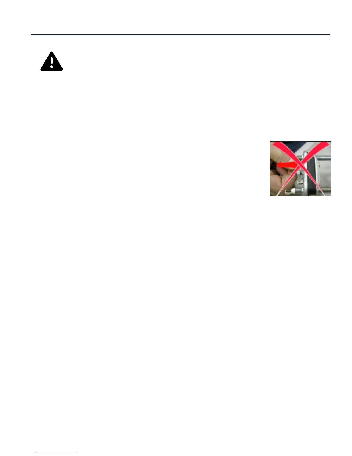
• Replace the heating element with the one that has the same characteristics (2
thermal fuses) to maintain safety measures for the Appliance. Do not remove / switch
the NTC sensors between heating elements (See Figure).
• Always empty the Appliance before laying it on its side for any servicing.
• Do not lay down the machine on Electronic Control System side while servicing the
unit. In such cases, some water in the detergent dispenser could sip into the electrical
/ electronic components and cause these to burn.
• The resistance values of the components shown in this SM (Service Manual) are purely
indicative and approximate.
Heating Element with
Different Characteristics
• Do not place any container under the Appliance to avoid collecting drops of water.
• Always place the cotton cloth below the machine to absorb water. There is a possibility of water leakage
while servicing the Pumps and Dispenser.
7
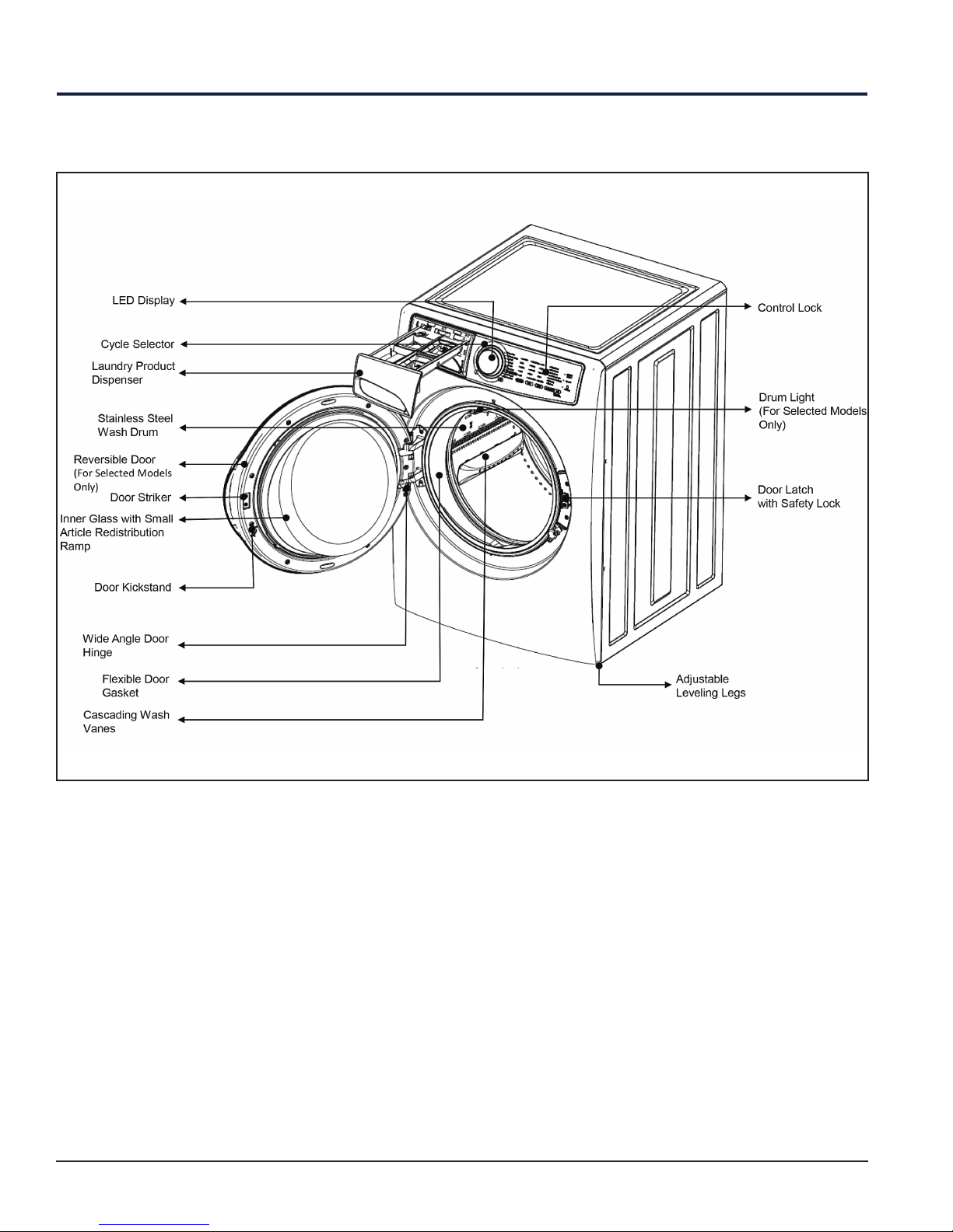
4. Product Features
4.1 EFLS617SIW / EFLS517SIW / EFLS417SIW
8
5. Model Specifications
5.1 Electric Front Load Washers
Description EFLS617SIW EFLS517SIW EFLS417SIW
Total Capacity D.O.E. 4.4 Cu. Ft. 4.3 Cu. Ft. 4.3 Cu. Ft.
Washer Drum Interior Stainless Steel Stainless Steel Stainless Steel
Lifetime Warranty Tub Yes Yes Yes
Interior Light Yes Yes No
Door Trim Chrome Chrome White
Vibration Control System Yes Yes Ye s
Advanced Rinse Technology Yes Yes Ye s
TimeWise® Technology Yes Yes Ye s
Ready Clean™ No No No
Ready Steam™ Perfect Steam Perfect Steam No
Extra Rinse Option Yes Yes Ye s
Extended Refresh option Yes Yes No
Perfect Steam option Yes Yes No
StainSoak option Yes No No
StainTreat II No Yes No
StainTreat No No Yes
Sanitize option Ye s Yes No
Stay-Fresh™ Door Seal Yes Yes Ye s
Temperature Control Automatic Automatic Automatic
Water Level Adjustments Automatic Automatic Automatic
Auto Prewash Detergent Dispenser Yes Yes Ye s
Auto Bleach Dispenser Yes Yes Ye s
Auto Detergent Dispenser Yes Yes Yes
Auto Fabric Softener Dispenser Yes Yes Ye s
Time Remaining Display Yes Yes Yes
Cycle Status Display Yes Yes Yes
Cycle Signal Chime + LED Chime Chime
Cycle Signal "ON / OFF": Yes Yes Yes
Cycle Signal Volume Control No No No
Mute / Unmute Yes Yes Yes
Door Lock Indicator Display Yes Yes Ye s
Control Lock Yes Yes Ye s
Stay Put Door Yes Yes Ye s
Start / Pause / Cancel Buttons Yes Yes Ye s
Energy Saver Option (Leaf Icon) Yes Yes Ye s
Delay Start Yes (Up to 16 Hr) Yes (Up to 16 Hr) Yes (Up to 16 Hr)
Integral Water Heater Yes, 1000 Watts Yes, 1000 Watts No
Tumble Speed (RPM) Variable Variable Variable
9
Model Specifications
Description EFLS617SIW EFLS517SIW EFLS417SIW
Spin Speed 1300 Max. RPM 1300 Max. RPM 1300 Max. RPM
Sound Package SilentDesign™
Leveling Legs Adjustable Adjustable Adjustable
Cycles
Wash Cycles 8 8 6
Specialty Cycles 1 1 1
Total Cycles 9 9 7
Heavy Duty Yes Yes Ye s
Whitest Whites Yes Yes Yes
Normal Yes Yes Ye s
Casual Yes Yes No
Colors Yes Yes No
Fast Wash Yes (15 min) Yes (18 min) Yes (20 min)
Delicates Yes Yes Ye s
Rinse & Spin Yes Yes Yes
Clean Washer Yes Yes Ye s
Options
Water Temperature Selections 5 5 4
Water Levels Automatic Automatic Automatic
Spin Speed 5 5 4
Soil Level Selections 5 5 4
Allergen No No No
Certifications
ENERGY STAR® Most Efficient
NSF ® Certified Sanitize Yes Yes No
Specifications
Power Supply Connection Location Right Top Rear Right Top Rear Right Top Rear
Water Inlet Connection Location Left Top Rear Left Top Rear Left Top Rear
Voltage Rating 120 V / 60 Hz / 15 A 120 V / 60 Hz / 15 A 120V / 60 Hz / 15 A
Connected Load (KW ) @ 120 V
Watts @ 120 Volts / A @ 120 V 1,100 Watts / 10 A
Minimum Circuit Required 15 A 15 A 15 A
Dimensions and Weights
Overall Width 27" 27" 27"
Overall Depth 32” (811.7) 32” (811.7) 32” (811.7)
Overall Depth with Door Open 90° 53.5” 53.5” 53.5”
Overall Height 38” 38” 38”
Overall Height (Stacked) 75.75” 75.75” 75.75”
Pedestal Width 27" 27" 27"
1
Yes Yes Ye s
2
1.1 KW 1.1 KW 1.1 KW
10
Model Specifications
Description EFLS617SIW EFLS517SIW EFLS417SIW
Pedestal Depth 26 - 1/2" 26 - 1/2” 26 - 1/2”
Pedestal Depth with Drawer
Extended
Pedestal Height 15.25” 15.25” 15.25”
Shipping Weight (Approx.) 222.0 Lbs 222.0 Lbs 222.0 Lbs
NOTE
1. Recognized as the Most Efficient of ENERGY STAR® in 2016.
2. For use on adequately wired 120 V dedicated circuit having 2-wire service with a separate ground
wire. Appliance must be grounded for safe operation.
42 - 1/2" 42 - 1/2” 42 - 1/2”
11
6. Technical Characteristics
Liquid Bleach
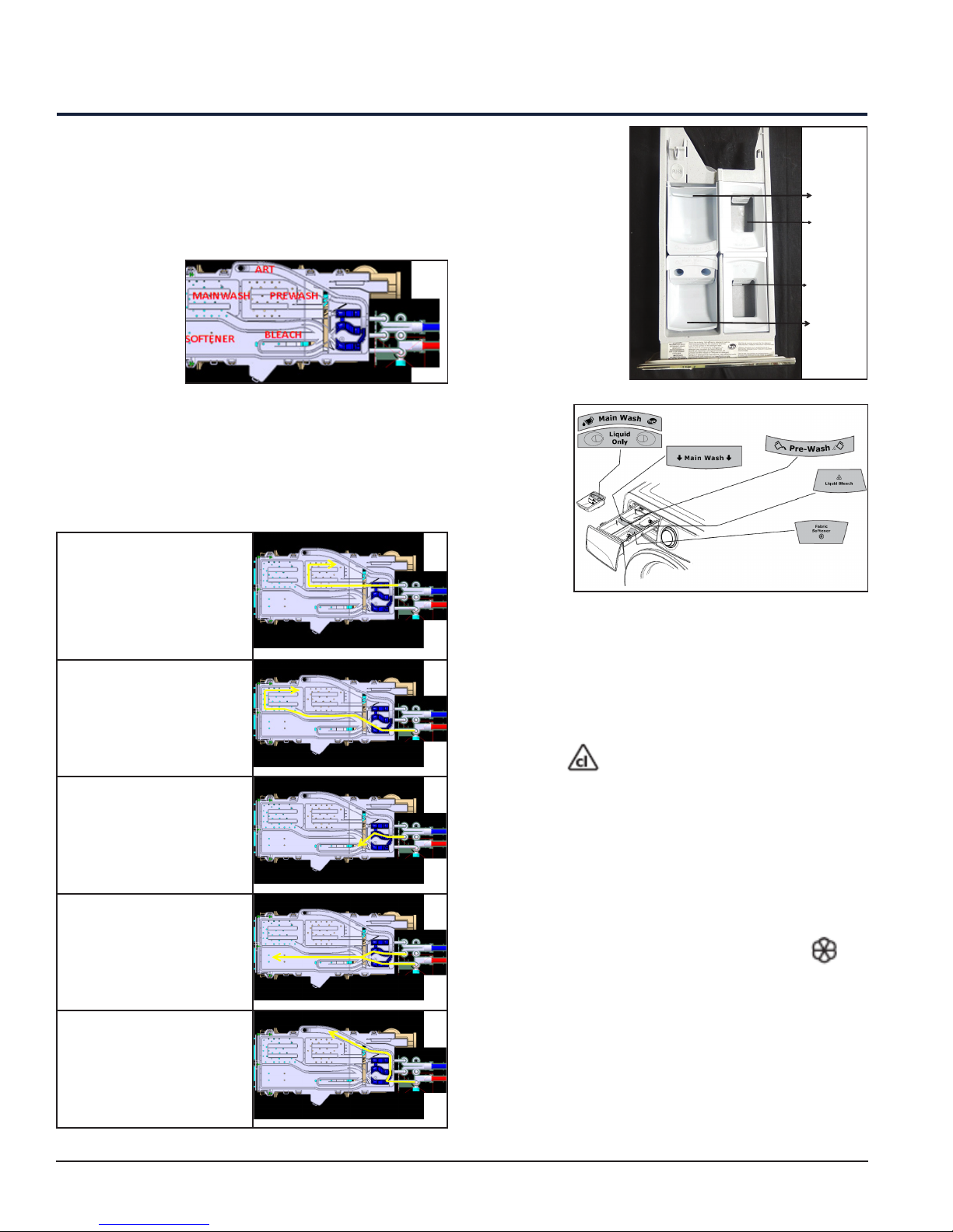
6.1 Detergent Dispenser
6.1.1 Detergent Dispenser with
Multi-Way Solenoid Valves
The water in
the detergent
dispenser is
filled through a
Solenoid Valve
for both cold
and hot water.
The detergent dispenser has 4 compartments and
one inlet for ART (Advanced Rinse Technology).
6.1.2 Operating Principle of
4-Way Compartment Conveyor
Water fill to Pre-Wash
compartment (Cold
Water)
Main Wash
Liquid Detergent
– Add the
recommended
amount of a highefficiency liquid
detergent to the
“Main wash-liquid
only” cup. Do not
exceed the Max.
fill line. Liquid
Detergent can also
be added directly
to the
Main Wash
Chamber
when not
using the
Pre-Wash
chamber.
Powder
Detergent
– To use
high-efficiency powder detergent, remove the “Main
Wash – Liquid only” cup and add the powder directly
to the Main Wash Detergent Chamber.
Pre-Wash
Fabric Softener
Main Wash
Water fill to Main wash
compartment (Cold,
Warm and Hot water)
Water fill to Bleach
compartment (Cold
Water)
Water fill to Softener
compartment (Warm
Water)
Advanced Rinse
Technology - ART (Cold /
Warm Water)
Liquid Chlorine Bleach
• If desired, add liquid chlorine bleach to the
chamber labelled “Liquid Bleach” marked with this
symbol .
• Fill to the Min. line for small loads and the Max.
line for large loads.
• Do not fill above the Max. line.
Liquid Fabric Softener
• If desired, pour the recommended amount of
liquid Fabric softener into the chamber labelled
“Fabric Softener” marked with the symbol .
• Fill to the Min. line for small loads and the Max.
line for large loads.
• Do not fill above the Max. line.
Detergent for Pre-wash
For Heavily soiled or stained loads, select the prewash option and add the recommended amount of
detergent to the “Pre-Wash” detergent cup.
12
7. Electrical Characteristics
7.1 Electronic Control
The Electronic Control is made up of the following:
1. User Interface (UI) Board
2. Main Control Board (Positioned inside the machine on the right side near to the Rear Panel)
3. Motor Control Board (Positioned at the bottom left of the Appliance seen from the rear)
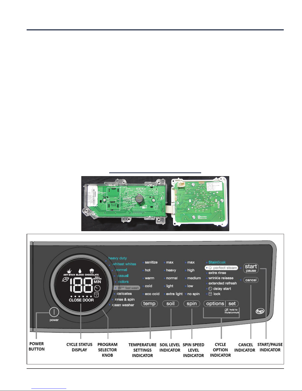
7.1.1 User Interface (UI) Board
The User Interface (UI) Board contains: the selector dial to select the washing programme, the LCD display to
display the programme, status, time and so on information. Buttons are available to adjust the following: the
washing temperature, the spin speed, to select an option, the degree of drying and lastly the start / pause
button to pause or start a programme, while cancel button acts as OFF.
It is possible to select the programmes by turning the selector. The options can be selected by pressing /
touching the buttons. The start / pause button is used to start the machine or pause it. The buzzer - where
featured, is powered by the User Interface (UI) Board.
User Interface (UI) Board – EFLS617SIW
13
Electrical Characteristics
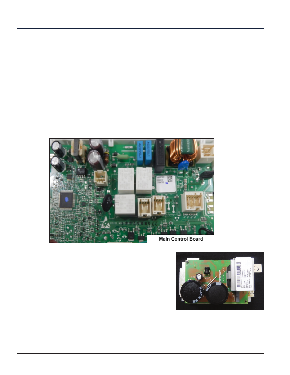
7.1.2 Main Control Board
The Main Control Board supplies the power supply voltage to the Motor control and User Interface (UI) Board
and all other electrical components.
The commands acquired by the User Interface Board (by turning the selector, selecting an option and so on)
are sent to the Main Control Board, which powers all the electrical components (Solenoid Valve, Drain Pump,
Heating Element Assembly, Door Lock, Motor Control Board and the Display Board).
1. It controls the level of water via the analog Pressure Sensor.
2. It controls and monitors the status of the door.
3. It controls the temperature of the wash water via NTC probe inserted in the heating element.
4. It controls the voltage and frequency of the power supply and ensures they are close to the rated ones.
5. It controls the flow of water through the Solenoid Valve.
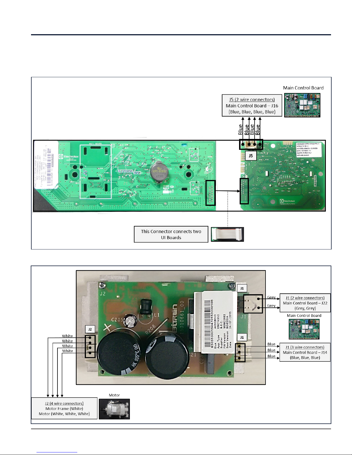
7.1.3 Motor Control Board
Motor Control Board transforms the energy from single-phase to threephase, which can be modulated in breadth and frequency respectively
to adjust the power and number of revolutions of the motor.
It receives signals from the main control board and sends voltage to
the drive motor to spin the drive motor in the proper direction and at
the proper speed. The motor control board detects the speed of the
drive motor through a tachometer component. If the motor control is
not working properly, the drive motor might not spin at all or might spin
at the wrong speed.
Motor Control Board
14
Electrical Characteristics
7.2 Schematic Diagrams - EFLS617SIW / EFLS517SIW / EFLS417SIW
7.2.1 User Interface Board
7.2.2 Motor Control Board
15
Electrical Characteristics
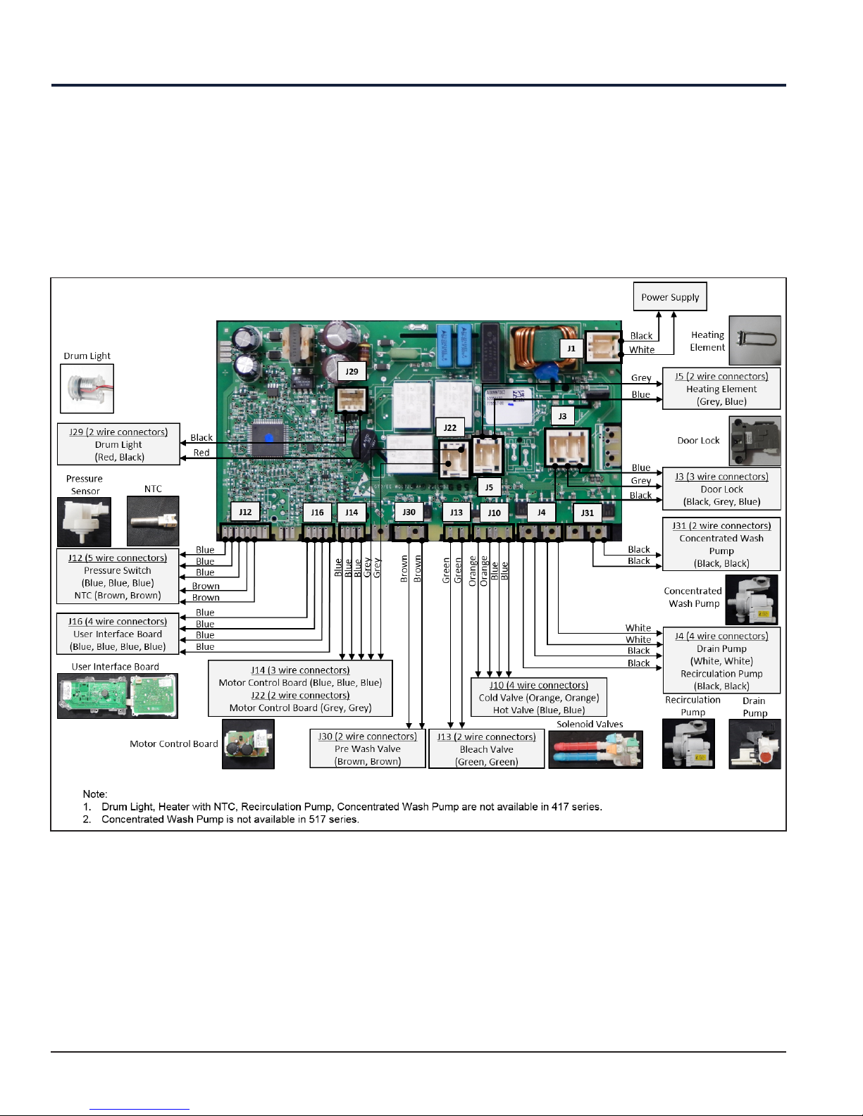
7.2.3 Main Control Board
16
Electrical Characteristics
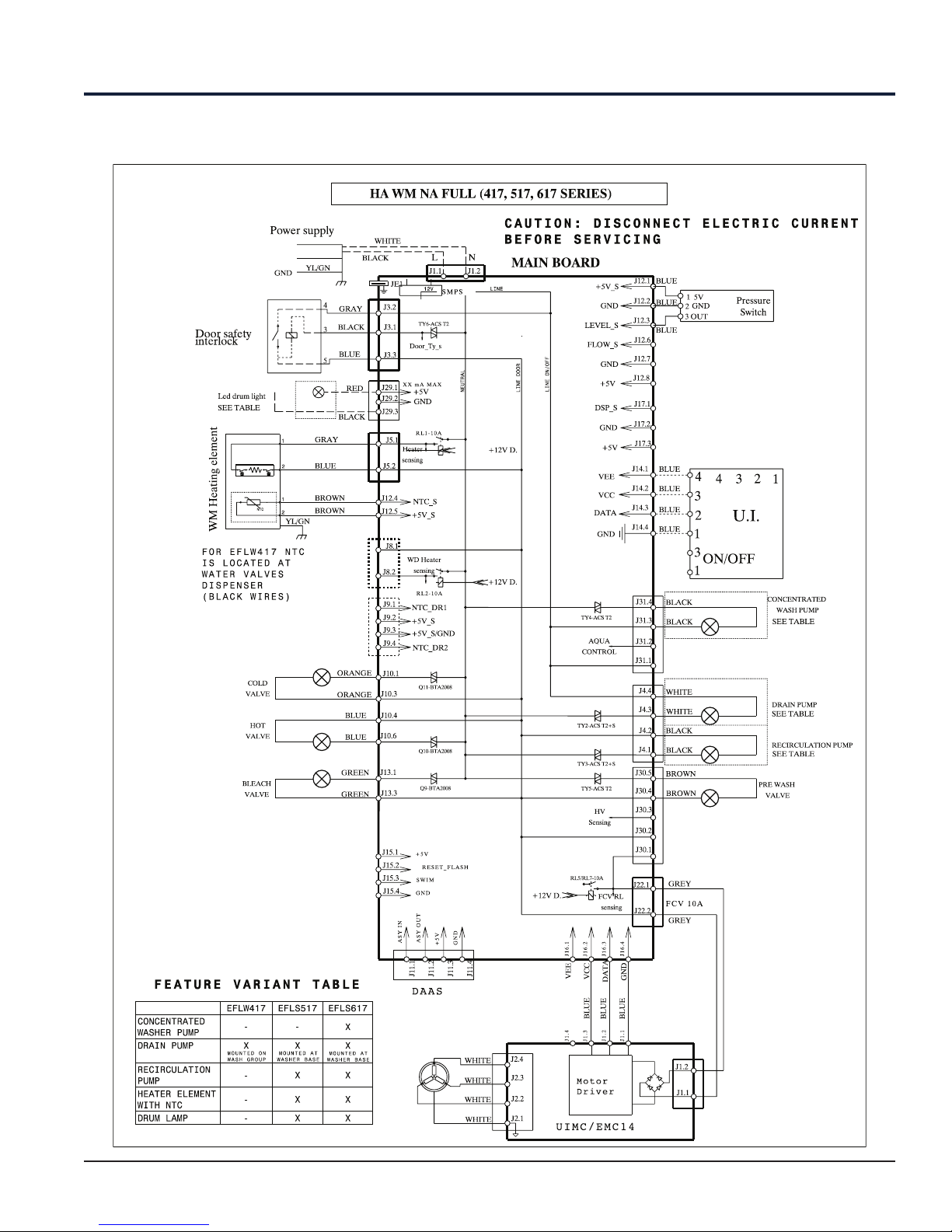
7.3 Wiring Diagram - EFLS617SIW / EFLS517SIW / EFLS417SIW
17
8. Electrical Components – EFLS617SIW / EFLS517SIW /
EFLS417SIW
Electrical Component Resistance and Specification Table
S. No. Component Resistance Specification
Supply voltage 120 V (95-132 V
1 Door Lock --
2 Dispenser Solenoid valve Coils resistance @25ºC 990±10% Ω
3 Motor --
60Hz) / 230 V (180-265 V 50-60
Hz), Coil insulation: F
Cold water temperature-25 ºC
Hot water temperature-60 ºC
Coils room temperature-60 ºC
Nominal Voltage-120 V
Voltage tolerance-(-15% + 10%)
Nominal Frequency-60 Hz
200 V, 4 A, 330 Hz. (Max.),
RPM (Max.), - 18,600, Insulation
Class-F
4
5
6 Pressure Sensor --
7
(Not applicable for 417 series)
(Not applicable for 417 series)
(Not applicable for 417 series)
Heating Element
NTC
LED Drum Light
13 Ω to 15 Ω 120 V, 60 Hz, 1000 W
Temp Ω
0 ºC 15771 ± 6.1%
30 ºC 3891 ± 4%
40 ºC 2573 ± 3.4%
50 ºC 1742 ± 2.8%
60 ºC 1204 ± 2.2%
70 ºC 849 ± 2.4%
95 ºC 383 ± 3.6%
--
--
5 ± 0.25 V DC, 5 mA (Max.)
85 ºC operating temp (Max.)
44 Hz empty drum
Everlight LED
ELSW-F91C1-OLPGS-C6500
350 mA (Max. LED Current)
Power 1 W
Min. Flux:35 Lumen (55 Typical)
White LED (Cold White) Typical
6500 K
Recirculation pump
(Not applicable for 417 series)
8
and Concentrated Wash Pump
(Not applicable for 417 and 517
series)
9 Drain Pump Winding Resistance-14 ± 10% Ω
31.5 ± 10% Ω @20 ºC
18
Nominal Voltage-120 V, 60
Hz, Insulation Class F (155),
Working Voltage 95-132 V
Rated-120 VAC / 60 Hz,
Working Voltage-95-132 V AC,
Current and Power with Rotor
locked-1.4 A, 80 W Max.
 Loading...