

Page 1
Instructions Manual
Manuel d’Instructions
Bedienungsanleitung
Manual de instrucciones
Kullanim Kilavuku
EFC 6540
EFC 7540
EFC 9540
EFC 1540
Libretto di Istruzioni
Page 2

EN FR DE ES TR
INDICE
CONSIGLI E SUGGERIMENTI ..............................................................................................................................................3
CARATTERISTICHE..............................................................................................................................................................4
INSTALLAZIONE....................................................................................................................................................................5
USO........................................................................................................................................................................................8
MANUTENZIONE.................................................................................................................................................................10
IT
INDEX
RECOMMENDATIONS AND SUGGESTIONS....................................................................................................................12
CHARACTERISTICS............................................................................................................................................................13
INSTALLATION ....................................................................................................................................................................14
USE.......................................................................................................................................................................................17
MAINTENANCE....................................................................................................................................................................19
SOMMAIRE
CONSEILS ET SUGGESTIONS ..........................................................................................................................................21
CARACTERISTIQUES.........................................................................................................................................................22
INSTALLATION ....................................................................................................................................................................23
UTILISATION........................................................................................................................................................................26
ENTRETIEN..........................................................................................................................................................................28
INHALTSVERZEICHNIS
EMPFEHLUNGEN UND HINWEISE....................................................................................................................................30
CHARAKTERISTIKEN..........................................................................................................................................................31
MONTAGE............................................................................................................................................................................32
BEDIENUNG.........................................................................................................................................................................35
WARTUNG............................................................................................................................................................................37
ÍNDICE
CONSEJOS Y SUGERENCIAS ...........................................................................................................................................39
CARACTERÍSTICAS............................................................................................................................................................40
INSTALACIÓN......................................................................................................................................................................41
USO......................................................................................................................................................................................44
MANTENIMIENTO................................................................................................................................................................46
IÇERIKLER
TAVSIYELER VE ÖNERILER ..............................................................................................................................................48
ÖZELLIKLER........................................................................................................................................................................49
MONTAJ...............................................................................................................................................................................50
KULLANIM............................................................................................................................................................................53
BAKIM...................................................................................................................................................................................55
2
2
Page 3

IT
CONSIGLI E SUGGERIMENTI
Questo libretto di istruzioni per l'uso è previsto per più versioni
dell' appare
c
chio.
650 mm min.
É possibile che siano descritti singoli particolari della dotazione, che non riguardano il Vostro apparec c hio.
INSTALLAZIONE
• Il produttore declina qualsiasi responsabilità per danni dovuti ad installazione non
corretta o non confor me alle regole d ell’art e.
• La distanza minima di sicurezza tra il Piano di cottura e la Cappa deve essere di
650 mm, (alcuni modelli possono esser e installati ad un’alt ezza inferiore, fare riferimento ai paragrafi i ngo mbro e i nst al laz ione) .
• Verificare che la tensione di rete corrisponda a quella riportata nella targhetta
posta all’interno della Cappa.
• Per Apparecchi in Cl asse I
sca un corretto sc ar ic o a ter ra.
• Collegare la Cappa all’uscita dell’aria aspirata con tubazione di diametro pari o
superiore a 120 mm. Il percorso della tubazione deve essere il più breve possibile.
• Non collegare la Cappa a condotti di scarico dei fumi prodotti da combustione
(caldaie, caminet ti , ec c.) .
• Nel caso in cui nella stanza vengano utilizzati sia la Cappa che apparecchi non
azionati da energia elettrica (ad esempio apparecchi utilizzatori di gas), si deve
provvedere ad una aerazione sufficiente dell’ambiente. Se la cucina ne fosse
sprovvista, praticare un’apertura che comunichi con l’esterno, per garantire il richiamo d’aria pulita.
USO
• La Cappa è stata progettata esclusivamente per uso domestico, per abbattere gli
odori della cucina.
• Non fare mai uso improprio dell a Cap pa.
• Non lasciare fiamme libere a f ort e int ens it à sott o la Cappa i n funz ione.
• Regolare sempre le fiamme in modo da evitare una evidente fuoriuscita laterale
delle stesse ri spet t o al fondo dell e p entol e.
• Controllare le friggit ric i durant e l’ uso: l’ oli o surri scal dat o potr ebbe i nf iammar si .
• Non preparare alimenti f lambè s ot to l a cappa da c uc ina; peri c olo d'i ncen di o.
• Questo apparecchio non deve esse re utiliz zato da persone (b ambini in clusi) con
ridotte capacità psichiche, sensoriali o mentali, oppure da persone senza esperienza e conoscenza, a meno che non siano controllati o istruiti all’uso
dell’apparecchio da person e r esponsabili della loro sicurezza.
• I bambini devono essere supervisionati per assicurarsi che non giochino con
l’apparecchio.
MANUTENZIONE
• Prima di procedere a qualsiasi operazione di manutenzione, disinserire la Cappa
togliendo la spina elettrica o spegnendo l’interruttore generale.
• Effettuare una scrupolosa e tempestiva manutenzione dei Filtri secondo gli intervalli consigliati (Rischio di incendio).
• Per la pulizia delle su pe rfici d e lla C a ppa è suffi cie n te u tiliz za re u n pa nno um ido e
detersivo liqui do neutr o.
a
accertarsi ch e l’imp ianto e lettrico dome stico ga ranti-
Il simbolo sul prodotto o sulla confezione indica che il prodotto non deve essere considerato
come un nor m ale rifiuto dom estico, ma dev e es sere portato n el p u nto di raccolta a ppropriato per
il ricicl aggi o di a ppar ec c hi atur e el et tri che e d el et tro nic he. P r ovv edendo a smaltire questo prodotto in modo appropriato, si contribuisce a evitare potenziali conseguenze negative per l’ambiente
e per la salute, che potrebbero derivare da uno smaltimento inadeguato del prodotto. Per informazioni più dettagliate sul riciclaggio di questo prodotto, contattare l’ufficio comunale, il servizio
locale di smaltimento rifiut i o il negozio in cui è stato acqu istat o il prodot to .
3
3
Page 4

IT
CARATTERISTICHE
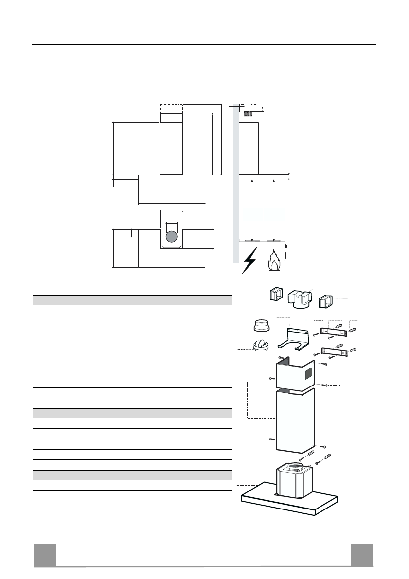
740
108
490 60
598-698-898-1198
300
150
Ingombro
870
260
1200
Min.
650mm
42
Min.
650mm
64
Componenti
Rif. Q.tà Componenti di Prodotto
1 1 Corpo Cappa completo di: Comandi, Luce, Gruppo
Ventilatore, Filtri
2 1 Ca mino Telescopico formato da:
2.1 1 Camino Superiore
2.2 1 Camino Inferiore
9 1 Flangia di Riduzione ø 150-120 mm
10 1 Flangia con valvola
14.1 2 Prolunga Raccordo Uscita Aria
15 1 Raccordo Uscita Aria
Rif. Q.tà Componenti di Installazione
7.2.1 2 Staffe Fiss aggi o Camino Superiore
7.3 1 Staffa Sostegno Raccordo
11 6 Tasselli
12a 6 Viti 4,2 x 44,4
12c 6 Viti 2,9 x 9,5
Q.tà Documentazione
1 Libretto Istruzioni
15
14.1
7.3
9
10
2.1
2
2.2
1
12a
7.2.1 11
12c
11
12a
4
4
Page 5

IT
INSTALLAZIONE
Foratura Parete e Fissaggio Staffe
7.2.1
7.3
1÷2
X
11
12a
320
116
116
650 min.
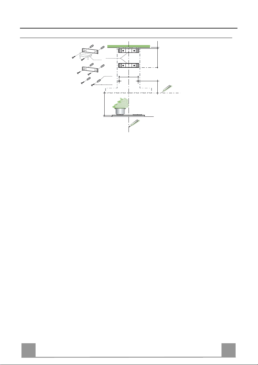
Tracciare sulla Parete:
• una linea Verticale fino al soffitto o al limite superiore, al centro della zona prevista per il
montaggio della Cappa;
• una linea Orizzontale a: 650 mm min. sopra il Piano di Cottura.
• Appoggiare come indicato la Staffa 7.2.1 a 1-2 mm dal soffitto o dal limite superiore, allineando il suo centro (intagli) sulla linea Verticale di riferimento.
• Segnare i centri dei Fori della Staffa.
• Appoggiare come indicato la Staffa 7.2.1 a X mm sotto la prima staffa (X = altezza Camino
Superiore in dotazione), allineando il suo centro (intagli) sulla linea Verticale di riferimento.
• Segnare i centri dei Fori della Staffa.
• Segnare come indicato, un punto di riferimento a 116 mm dalla linea Verticale di riferimento, e 320 mm sopra la linea Orizzontale di riferimento.
• Ripetere questa operazione dalla parte opposta.
• Forare ø 8 mm i punti segnati.
• Inserire i tasselli 11 nei fori.
• Fissare la Staffa inferiore 7.2.1 utiliz z ando le Vi ti 12a (4,2 x 44,4 ) in do tazione.
• Fissare insieme la Staffa superiore 7.2.1 e la Staffa sostegno raccordo 7.3 utilizzando le 2
viti 12a (4,2 x 44,4) in dotazione.
• Avvitare 2 Viti 12a (4,2 x 44,4) in dotazione nei fori per il fissaggio del corpo Cappa, lasciando uno spazio di 5-6 mm fra la parete e la testa della vite.
5
5
Page 6

IT
Montaggio Corpo Cappa
9
ø 120ø 150
10
10
ø 150
15
14.1
7.3
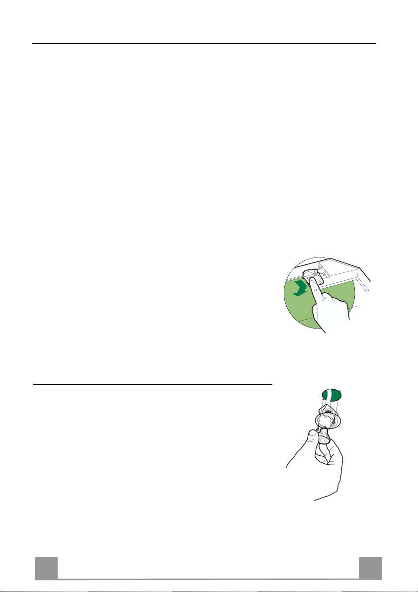
• Prima di agganciare il Corpo Cappa, serrare le 2 Viti Vr situate
sui punti di aggancio del Corpo Cappa.
• Agganciare il Corpo Cappa alle Viti 12a.
• Serrare definitivamente le Viti 12a di supporto.
• Agire sulle Viti Vr per livellare il Corpo Cappa.
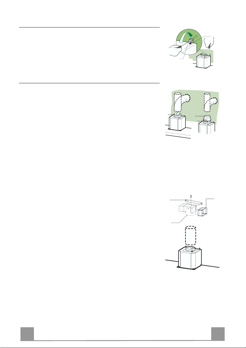
Connessioni
USCITA ARIA VERSIONE ASPIRANTE
Per installazione in Versione Aspirante collegare la Cappa alla
tubazione di uscita per mezzo di un tubo rigido o flessibile di
ø150 o 120 mm, la cui scelta è lasciata all'installatore.
Collegamento tubo ø 150
• Inserire la Flangia ø 150 10 sull’Uscita del Corpo Cappa.
• Fissare il tubo con adeguate fascette stringitubo. Il materiale
occorrente non è in dotazione.
Collegamento tubo ø 120
• Per collegamento con tubo ø120 mm, inserire la Flangia di riduzione 9 sulla flangia ø 150 10 precedentemente installata.
• Fissare il tubo con adeguate fascette stringitubo. Il materiale
occorrente non è in dotazione.
• In ambedue i casi, togliere eventuali Filtri Antiodore al Carbone attivo.
Vr
12a
USCITA ARIA VERSIONE FILTRANTE
• Inserire lateral mente le Prolun ghe Raccordo 14.1 sul Raccordo
15.
• Inserire il Raccordo 15 nella Staffa di Sostegno 7.3 fissandolo
con una Vite.
• Assicurarsi che l ’uscita delle Prolunghe Raccord o 14.1 risulti
in corrispondenza delle bocchette del Camino sia in orizzontale
che in verticale.
• Collegare il Raccordo 15 all’Uscita del Corpo Cappa per mezzo di un tubo rigido o flessibile di ø150 mm, la cui scelta è lasciata all'installatore.
• Assicurarsi della presenza del Filtro Antiodore al Carbone attivo.
6
6
Page 7
IT
CONNESSIONE ELETTRICA
12c
2.1
2.2
2
7.2.1
12c
• Collegare la Cappa all’Alimentazione di Rete interponendo un
Interruttore bipolare con apertura dei contatti di almeno 3 mm.
• Rimuovere i Filtri antigrasso (vedi par. “Manutenzione”) e assicurarsi che il connettore del Cavo di alimentazione sia correttamente inserito nella presa dell’Aspiratore
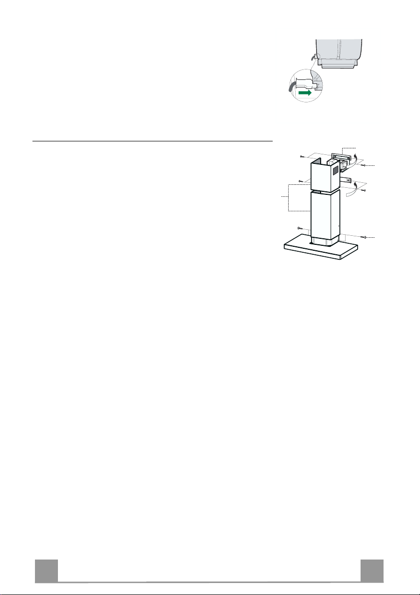
Montaggio Camino
Camino superiore
• Allargare leggermente le due falde laterali, agganciarle dietro
le Staffe 7.2.1 e richiuderle fino a battuta.
• Fissare lateralmente alle Staffe con 4 Viti 12c (2,9 x 9,5) in
dotazione.
• Assicurarsi che l’uscita delle Prolunghe Raccordo risulti in corrispondenza delle bocc hette de l C am i no.
Camino inferiore
• Allargare leggermente le due falde laterali del Camino, agganciarle tra il Camino superiore e la parete e richiuderle fino a
battuta.
• Fissare lateralmente la parte inferiore al Corpo Cappa, con 2
Viti 12c (2,9 x 9,5) in dotazione.
7
7
Page 8
IT
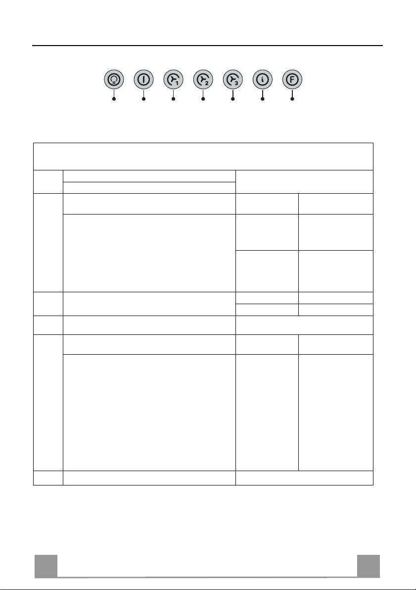
USO
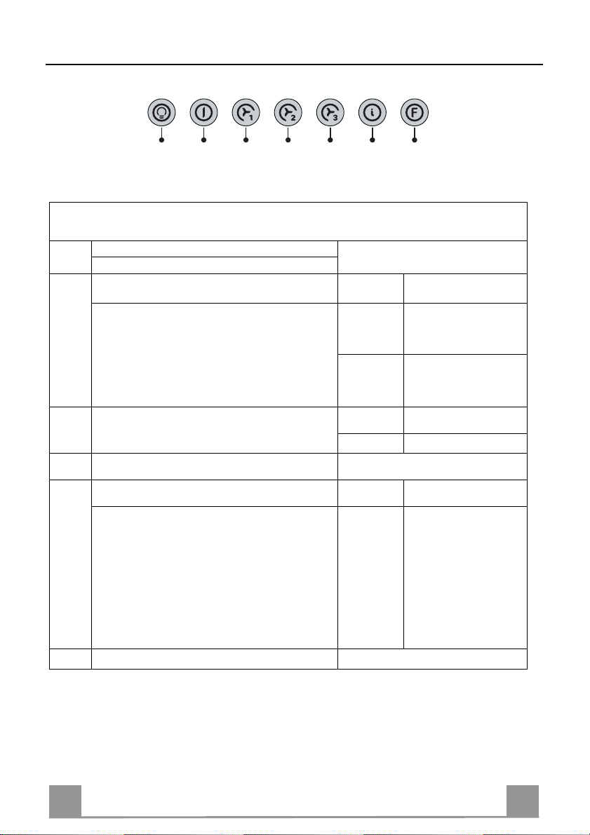
L T1 T2 T3 T4 T5 F
La cappa può essere accesa direttamente alla velocità desiderata, premendo il relativo tasto
senza passare per il tasto 0/1 motore.
Funzione base Tasto
Segnalazioni luminose
Doppia Funzione
Premuto brevemente accende e spegne l’im pianto di
L
illuminazione.
Premendo il tasto per 2 secondi si attiva l’impianto
di illuminazione in modalità “luce di cortesia”. Le
lampade ven gono alimentat e ad una potenza ridotta
di circa 5W. Tale funzione può essere disinserita ripremendo il tasto per 2 secondi o premendolo brevemente per passare alla normale modalità di illuminazione. Nella modalità luce di cortesia il tasto non è
illuminato.
Spegne il motore da qualsiasi velocità impostata
T1
Attiva il motore alla prima velocità
T2
Premuto brevemente attiva il motore alla seconda veloci-
T3
tà
Premendo per circa 2” il tasto, si attiva la funz ione
Delay, cioè lo spegnimento rit ardato
dell’appar ecchio. Adatto per completare
l’eliminazione di odori residui. Attivabile dalla posizione OFF e dall e velocità 1, 2, 3 ; si disattiva anticipatamente premendo qualsiasi tasto (T) ad eccezione di T3. I l Delay avviene secondo il segu ente
schema:
1° velocità / OFF = 20 minuti
2°velocità = 15 minuti
3°velocità = 5 minuti
Attiva il motore alla terza velocità
T4
Tasto spento Luci spente
Tasto illuminato
Tasto spento Luce di c ortesia acces a
Tasto illuminato
Tasto spento Motore inattivo
Tasto acceso Seconda velocità attiva
Tasto lam-
peggiante
Luci accese
Motore attivo
Tasto acceso
Funzione Delay
Attiva
Tasto acceso
8
8
Page 9
IT
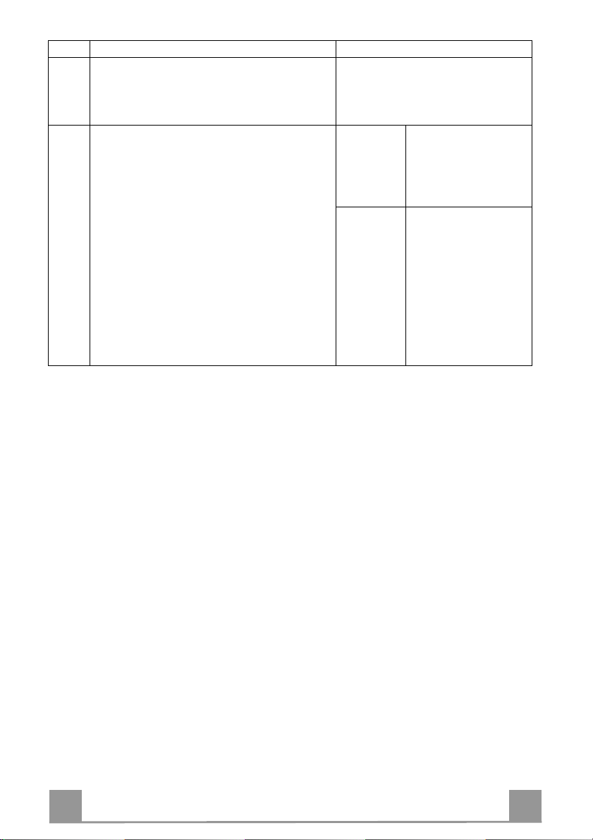
Tasto Funzione base Segnalazioni luminose
Attiva il motore alla velocità intensiva temporizzata a 5
T5
minuti. Al termine dei 5 minuti l’apparecchio ritorna alla
velocità precedentemente impostata. Nel caso di attivazione da apparecchio spento alla scadenza dei 5 minuti il
sistema ritorna all a pri ma vel oc it à.
Premuto per 4 se condi ripr istina la se gnalazione d i allar-
F
me filtri segnalandola con il lampeggio del tasto T1. Questa procedura è eseguibile solo a motore spento.
Tasto acceso
Tasto lampeggiante
Tasto acceso
Segnala l’allarme saturazione Filtri Antigrasso Metallici
e la necessità di lavarli.
L’allarme entra in funzione
dopo 100 ore di lavoro effettivo della Cappa.
Segnala, quando è attivato,
l’allarme saturazione Filtro
Antiodore al Ca rbo ne A ttivo ,
che deve essere sostituito;
devono anche essere lavati
i Filtri Antigrasso Metallici.
L’allarme saturazione Filtro
Antiodore al Carbone Attivo
entra in funzione do po 200
ore di lavoro effettivo della
Cappa. (Attivazione vedi
parag. Filtro antiodore)
9
9
Page 10
IT 110
MANUTENZIONE
Filtri antigrasso
PULIZIA FILTRI ANTIGRASSO METALLICI AUTOPORTANTI
Reset del segnale di allarme
• Spegnere il Motore di aspirazion e.
• Premere il tasto F per almeno 4 secondi, sino al lampeggio di
conferma del tasto T1.
Pulizia Filtri
• Sono lavabili anche in lavastoviglie, e necessitano di essere
lavati ogni 2 mesi circa di utilizzo o più frequentemente, per un
uso particolarmente intenso.
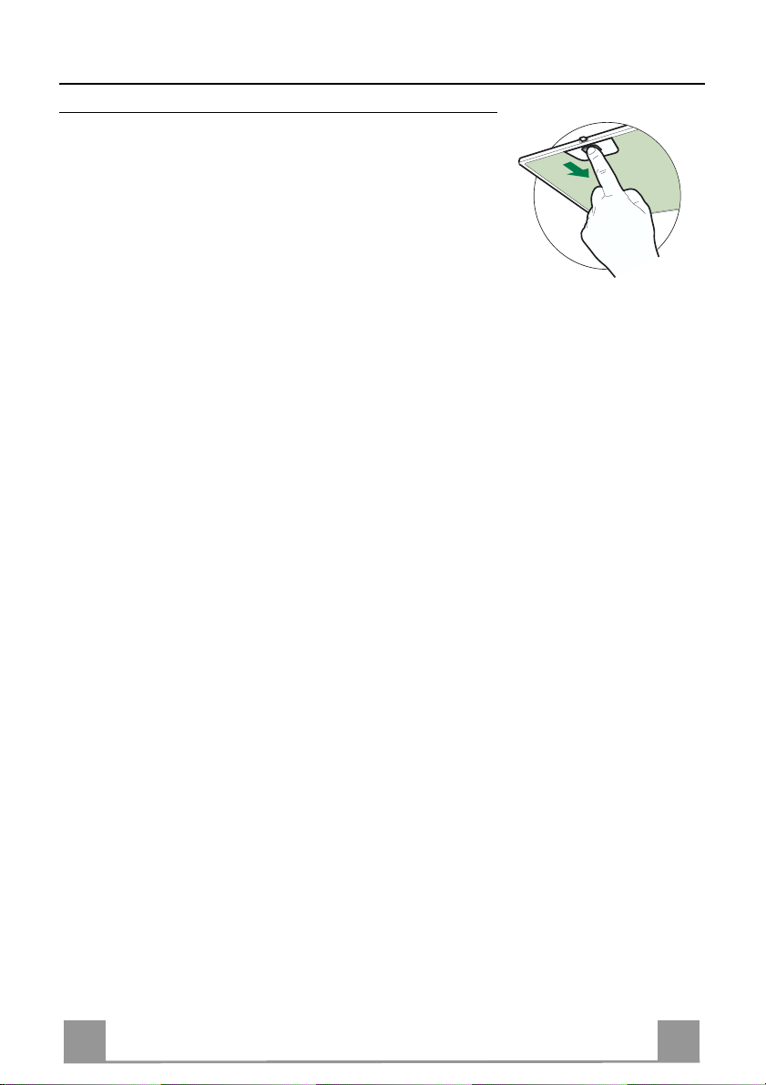
• Togliere i Filtri uno alla volta, spingendoli verso la parte posteriore del gruppo e tir ando contemporaneamente verso il basso.
• Lavare i Filtri evitando di piegarli, e lasciarli asciugare prima
di rimontarli.
• Rimontarli facendo attenzione a mantenere la maniglia verso la
parte visibile esterna.
Page 11
IT 111
Filtro antiodore (Versione Filtrante)
Non è lavabile e non è rigenerabile, va sostituito quando il tasto F lampeggia o almeno ogni 4
mesi. La segnalazione di allarme si verifica solo quando é azionato il Motore di aspirazione.
Attivazione/Dis attivazione del segnale di allarme
• Nelle Cappe in Versione Filtrante, la segnalazione di Allarme saturazione Filtri va attivata al
momento dell'installazione o successivamente.
• Spegnere le Luci e il Motore di aspirazione.
• Scollegare l’alimentazione di rete della Cappa sfilando il connettore del Cavo Alimentazione dal gruppo motore o azionando l'Interruttore bipolare interposto sull'alimentazione di Rete o agendo sull'Interruttore generale.
• Ripristinare il collegamento tenendo premuto il tasto T2.
• Rilasciare il tasto, i tasti L, T2 e F sono accesi in posizione fissa.
• Entro 3 secondi premere il tasto F sino al lampeggio di conferma del tasto stesso:
• 2 lampeggi - Allarme saturazione Filtro antiodore al Carbone ATTIVATO
• 1 lampeggio - Allarme saturazione Filtro antiodore al Carbone DISATTIVATO
SOSTITUZIONE FILTRO ANTIODORE AL CARBONE ATTIVO
Reset del segnale di allarme
• Spegnere il Motore di aspirazion e.
• Premere il tasto F per almeno 4 secondi, sino al lampeggio di
conferma del Tasto T1.
Sostituzione Filtro
• Togliere i Filtri antigrasso metallici.
• Rimuovere il Filtro antiodore al Carbone attivo saturo, agendo
sugli appositi agganci.
• Montare il nuovo Filtro agganciandolo nella sua sede.
• Rimontare i Filtri antigrasso metallici.
Illuminazione
SOSTITUZIONE LAMPADE
Lampade alogene da 20 W.
• Togliere le due viti che fissano il Supporto illuminazione e sfilarlo dalla Cappa.
• Estrarre la Lampada dal Supporto.
• Sostituirla con una nuova di uguali caratteristiche, facendo attenzione di inserire correttamente i due spinotti nella sede del
Supporto.
• Rimontare il Supporto fissandola con le due Viti precedentemente tolte.
Page 12

EN 112
RECOMMENDATIONS AND SUGGESTIONS
The Instructions for Us e a pply t o seve ral versio ns of this appl ianc e. Ac cor
d-
650 mm min.
ingly, you may fin d descriptions of indi vidual features that d o not apply to
your specific appliance.
INSTALLATION
• The manufact urer will not be held liabl e for any damages res ulting from incorrect or i mpr op er in sta l lat ion .
• The minimum safety distance between the cooker top and the extractor
hood is 650 mm (som e m od el s can be installed at a low er height, please refer to the paragraphs on working dimensions and installation).
• Check that the mains voltage cor responds to that indicated o n the rating
plate fixed to the inside of the hood.
• For Class I appliances, c heck that the domestic p ower supply guarantees
adequate earthing.
Connect the extract or t o the exh aust fl ue thr ough a pi pe of m inim um diam e-
ter 120 mm. The route of the flue must be as short as possible.
• Do not c onnect the extractor hood to exh aust ducts carrying combustion
fumes (boilers, fireplaces, etc.).
• If the extractor is used in c onjunction with non-electrical appliances (e.g. gas
burning applia nces), a suffi cient degree of aeration must be guarantee d in
the room in order to prevent t he backfl ow of exha ust gas. T he kitch en must
have an opening communicating directly with the open air in order to
guarantee the entry of clean air.
USE
• The extractor hood has been designed exclusively for domestic use to eliminate kitchen smells.
• Never use the hood for purposes other than for which it has been designed.
• Never lea ve hi gh na ked fl a me s unde r the ho od wh en i t is in op er at ion .
• Adjust the flame intensit y to direct it onto the bottom of t he pa n o nly , m aki ng
sure that it does not engulf the sides.
• Deep fat fryers m ust be continu ously monitored during use: ov erheated oil
can burst into flames.
• Do not flambè under the range hood; risk of fire
• This applianc e is not intended f or use by persons (i ncluding childre n) with
reduced physical , sensory or mental capabilitie s, or lack of ex perience and
knowledge, unless th ey have been g iven su pervi sion o r in structi on con cern ing use of the appliance by a person responsible for their safety.
• Children should be sup erv i se d to ensure that they do not play with t he appliance.
MAINTENANCE
• Switch off or unplug the appl i an c e fr om the m ains supply before carrying out
any maintenance work.
• Clean and/or replace the Filters after the specified time period (Fire hazard).
• Clean the hood using a damp cloth and a neutral liquid detergent.
The symbol on the product or on its packaging indicates that this product may not be treated
as household waste. Instead it shall be handed over to the applicable collection point for the
recycling of electrical and electronic equipment. By ensuring this prod uct is disposed of correctly,
you will help prevent potential negative consequences for the environment and human health,
which could otherwise be caused by inappropriate waste handling of this product. For more
detailed information about recycling of this product, please contact your local city office, your
household waste disposal service or the shop where you purchased the product.
Page 13
EN 113
CHARACTERISTICS
740
108
490 60
Dimensions
598-698-898-1198
300
150
Min.
650mm
42
Min.
650mm
64
1200
870
260
Components
Ref. Q.ty Product Components
1 1 Hood Body, complete with: Controls, Light, Blower,
Filters
2 1 Telescopic Chimney comprising:
2.1 1 Upper Section
2.2 1 Lower Section
9 1 Reducer Flange ø 150-120 mm
10 1 Damper ø 150
14.1 2 Air Outlet Conn ection Extension
15 1 Air Outlet Connection
Ref. Q.ty Installation Components
7.2.1 2 Upper Chimney Section Fixing Brackets
7.3 1 Air Outlet Connection Support
11 6 Wall Plugs
12a 6 Screws 4,2 x 44,4
12c 6 Screws 2,9 x 9,5
Q.ty Documentation
1 Instruction Manual
15
14.1
7.3
9
10
2.1
2
2.2
1
12a
7.2.1 11
12c
11
12a
Page 14
EN 114
INSTALLATION
Wall drilling and bracket fixing
7.2.1
7.3
1÷2
X
11
12a
116
116
320
650 min.
Wall marking:
• Dra w a vertical line on the supporting wall up to the ceiling, or as high as practical, at the
centre of the area in which the hood will be installed.
• Draw a horizontal line at 650 mm above the hob.
• P l ace bracket 7.2.1 on the wall as shown about 1-2 mm from the ceiling or upper limit aligning the centre (notch) with the vertical reference line.
• Mark the wall at the centres of the ho les in the bracket.
• P l ace br acket 7.2.1 on the wall as shown at X mm below the first bracket (X = height of the
upper chimney section supplied), aligning the centre (notch) with the vertical line.
• Mark the wall at the centres of the ho les in the bracket.
• Mark a reference point as in dicated at 116 mm from the vertical reference li ne and 320 mm
above the horizontal reference l ine.
• Repeat this operation on the other side.
• Drill ø 8 mm holes at all the centre points marked.
• Insert the wall plugs 11 in the holes.
• Fix the lower bracket 7.2.1 using the 12a screws (4,2 x 44,4) supplied.
• Fix the upper bracket 7.2.1 and the air outlet connect ion support 7.3 together using th e 2
screws 12a (4,2 x 44,4) supplied.
• Insert the two screws 12a (4,2 x 44,4) supplied in the hood body fixing holes, leaving a gap
of 5-6 mm between the wall and the head of the screw.
Page 15
EN 115
Mounting the hood body
9
ø 120ø 150
10
10
ø 150
15
14.1
7.3
• Before attaching the hood body, tighten the two screws Vr located on the hood body mounting points.
• Hook the hood body onto the screws 12a.
• Fully tighten support screws 12a.
• Adjust screws Vr to level the hood body.
Connections
DUCTED VERSION AIR EXHAUST SYSTEM
When installing the ducted version, connect the hood to the
chimney using either a flexible or rigid pipe ø 150 or 120mm, the
choice of which is left to the installer.
To install a ø 150
• To install the dumper 10
• Fix the pipe in position using sufficient pipe clamps (not supplied).
To install a ø 120
• To install a ø 120 mm air exhaust connection, insert the reducer flange 9 on the dumper 10.
• Fix the pipe in position using sufficient pipe clamps (not supplied).
• Remove any activated charcoal filters.
Vr
12a
RECIRCULATION VERSION AIR OUTLET
• Insert th e conn ection exten sion pieces lat erally 14.1 in co nnection 15.
• Insert the Connector 15 into the Support bracket 7.3 and fix it
with a screw.
• Make su re that the outlet of the extension pieces 14.1 is horizontally and vertically aligned with the chimney outlets.
• Connect th e air outlet connection 15 to the hood body outlet
using either a flexible or rigid pipe ø 150 mm, the choice of
which is left to the installer.
• Ensure that the activated charcoal filters have been inserted.
Page 16

EN 116
ELECTRICAL CONNECTION
12c
2.1
2.2
2
7.2.1
12c
• Connect the hood to the mains through a two-pole switch having a contact gap of at least 3 mm.
• Re move the grease filters (see paragraph Maintenance) being
sure that the conn ector of the feeding cable is correctl y insert ed
in the socket placed on th e side of the fan.
Flue assembly
Upper exhaust flue
• Slightly widen the two sides of the upper flue and hook them
behind the brackets 7.2.1, making sure that they are well
seated.
• Secure the sides to the brackets using t he 4 screws 12c (2,9 x
9,5) supplied.
• Make sure that the outlet of the extensi ons pieces is aligned
with the chimney outlets.
Lower ex haust flue
• Slightly widen the two sides of the flue and hook them between the upper flue and t he wall, making sure that they are
well seated.
• Fix the lower part laterally to the hood body using the 2 screws
12c (2,9 x 9,5) supplied.
Page 17
EN 117
USE
Dual Function
L T1 T2 T3 T4 T5 F
The hood can be switched on pushing directly onto the requested speed without firstly having to select 0/1 button .
Touch
control
T1
T2
T3
T4
Basic functions
When briefly pressed it switches the lighting system
L
on and off.
When pressed for 2 seconds it starts the lighting
system in “courtesy light” mode. The lamps are
fed at a reduced power of approximately 5W.
Such function can be stopped by pressing the
touch control for 2 seconds or just by pressing it
shortly in order to return to the normal lighting
mode. In courtesy light mode the touch control is
not lit.
When pressed the motor is stopped, regardless of the
speed it is set to.
When pressed the motor is set to the first speed
By a brief pressing the motor is set to the second
speed.
By pressing the touch control for approximately 2
seconds the Delay function is enabled, i.e de-
layed shutdown of the appliance ensuring a com-
plete elimination of the residual odours. This fun-
ction can be activated at OFF-position and at 1°,
2° and 3°speeds. It can be stopped in advance
by pressing any of the touch controls (T) with the
exception of T3. The Delay function works accor-
ding to the following scheme:
1°speed / OFF = 20 minuets
2°speed = 15 minutes
3°speed = 5 minutes
When pressed the motor is set to the third speed
Indicator lights
Touch control unlit Lights off
Touch control lit Lights on
Touch control unlit Courtesy light on
Touch control lit Motor on
Touch control unlit Motor off
Touch control lit
Touch control lit Second spe ed on
Flashing touch
control
Touch control lit
Delay function on
Page 18

EN 118
Touch
Touch control lit
control
T5
Basic functions Indicator lights
When pressed the motor is set to the intensive speed
timed to 5 minutes. At the end of 5 minutes of intensive speed the hood starts again at the speed it was
set to previously. In case the hood is set to the intensive speed directly from OFF-state it will then start
from the first speed after 5 minutes of intensive
speed.
When pressed for 4 seconds it resets the filter alarm
F
signal indicated by flashing of the touch control T1.
This procedure can be carried out only when the motor is stopped.
Flashing touch
control
Touch control lit
Metal grease filters saturation alarm. Metal gr e ase
filters need to be washed.
The alarm star ts up after
100 working hours.
Charcoal odour filter saturation alarm. Char coal
filter has to be replaced
and metal grease filters
washed. The alarm starts
up after 200 working
hours. (Activation; check
the paragraph “Odour
filter”)
Page 19

EN 119
MAINTENANCE
Grease filters
CLEANING OF THE METAL CASSETTE FILTERS
Alarm reset
• Stop the motor.
• Press the F -touch control for at least 4 seconds until the T1 -
touch control flashes.
Cleaning the filters
• Filters can be washed in the dish machine. They need to be
washed every 2 mont hs o r even more fr equ en tly in case of particularly intensive use of the hood.
• Remove the filters one by one pushing them towards the back
side of the unit and simultaneously pulling downwards.
• Any kind of bending of the filters has to be avoided when
washing them. Before fitting them again into the hood make
sure that they are completely dry.
• When fitting the filters into the hood pay attention that they are
mounted in correct position and that the handle faces outwards.
Page 20

EN 220
Odour filter (Recirculation Version)
This filter cannot be washed or regenerated, and must be replaced when the F touch control starts
to flash, or at least once ev e ry 4 months. The alarm is only triggere d w hen the m otor is on.
Enabling/Disabling the alarm signal
• In Recirculation Version Hoods, the Filter saturation Alarm must be enabled at the time of
installation or later.
• Switch off the lights and the motor.
• Disconnect the mains power supply to the hood by removing the motor unit power supply
cable connector, switching off the power supply at the Mains or turning the Main switch off.
• Restore the connection, pressing and holding T2.
• Release the touch control, touch controls L, T2 and F will light up normally.
• Within 3 seconds press the touch control F until the key itself flashes to confirm as follows:
• 2 flashes – Charcoal odour Filter saturation Alarm ENABLED
• 1 flash - Charcoal odour Filter saturation Alarm DISABLED
REPLACING THE CHARCOAL ODOUR FILTER
Reset the alarm signal
• Stop the motor.
• Press the touch control F for at least 4 seconds, until the touch
control T1 flashes.
Replace the Filter
• Remove the metal grease filters.
• Remove the sat urated charco al filter, tu rning the fasten ers provided.
• Fit the new filter and fasten it its correct position.
• Put the metal grease filters in their seats.
Lighting
LIGHT REPLACEMENT
20 W halogen light.
• Remove the 2 screws fixing the Lighting support, and pull it
out of from the Hood.
• Extract the lamp from the Support.
• Replace with another of the same t ype, making sure that th e
two pins are properly inserted in the lamp holder socket holes.
• Replace the Support, fixing it in place with the two screws removed as above.
Page 21

FR 221
CONSEILS ET SUGGESTIONS
650 mm min.
La présente notice d'emploi vaut pour plusieurs versions de l'appareil. Elle peut conte-
nir des descriptions d'accessoir es ne fi gurant pas dan s votr e apparei l.
INSTALLATION
• Le fabricant décline toute responsabilité en cas de dommage dû à un e in sta llatio n n on
correcte ou non conforme aux règles de l ’ art.
• La distance minimale de sécurité entre le plan de cuisson et la hotte doit être de 650
mm au moins (certains modèles peuvent être installés à une hauteur inférieure : se reporter aux paragraphes « Encombrem ent » et « Instal lati on »).
• Vérifier que la tension du secteur correspond à la valeur qui figure sur la plaquette
apposée à l’intérieur de la hotte.
• Pour les Appareils appartenant à la Ière Classe, veiller à ce que la mise à la terre de
l’installation électrique domestique ait été effectuée conformément aux normes en vigueur.
• Connecter la hotte à la sortie d’air aspiré à l’ai de d’une tuyauterie d’un diamètre égal ou
supérieur à 120 mm. Le parcours de la tuyaut eri e doit être le plus court possibl e.
• Ne pas connecter la hotte à des conduites d’évacuation de fumées issues d’une combustion tel que (Chaudière, chemi née, et c…).
• Si vous utilisez des appareils qui ne fonctionnent pas à l ’électricité dans la pièce ou est
installée la hotte (par exemple: des appareils fonctionnant au gaz), vous devez prévoir
une aération suffisante du milieu. Si la cuisine en est dépourvue, pratiquez une ouverture qui communique avec l’ext érieur pour garant ir l’infil trati on de l’ai r pur.
UTILISATION
• La hotte a été conçue exclusivement pour l’usage domestique, dans le but d’éliminer
les odeurs de la cuisine.
• Ne jamais utiliser abusivement la hotte.
• Ne pas laisser les flammes libres à forte intensité quand la hotte est en serv ice.
• Toujours régler les flammes de manière à éviter toute sortie latérale de ces dernières
par rapport au fond des marmites.
• Contrôler les friteuses lors de l’utilisation car l’hui le surc hauffée pour rai t s’ enfl ammer.
• Ne pas préparer d’aliments flambés sous la hotte de cuisine : ri sque d’i ncendie
• Cet appareil ne doit pas être utilisé par des personnes (y compris les enfants) ayant
des capacités psychiques, sensorielles ou mentales réduites, ni par des personnes
n’ayant pas l’expérience et la connaissance de ce type d’a ppar eils, à moins d'être sous
le contrôle et la formation de personn es respo nsables de l eur sécuri té.
• Les enfants doivent être surveillés pour s'assurer qu'ils ne jouent pas avec l'app arei l.
ENTRETIEN
• Avant de procéder à toute opération d’entretien, retir er la hotte en retirant la fi che ou en
actionnant l’interrupteur général.
• Effectuer un entretien scrupuleux et en temps dû des Filtres, à la cadence conseillée
(Risque d’incendie).
• Pour le nettoyage des surfaces de la hotte, il suffit d’utiliser un chiffon humide et détersif liquide neutr e.
Le symbole sur le produit ou son emballage indique que ce produit ne peut être traité comme
déchet ménager. Il doit plutôt être remis au point de ramassage concerné, se chargeant du recyclage du matériel électrique et électronique. En vous assurant que ce produit est éliminé correctement, vous favorisez la prévention des conséquences négatives pour l’environnement et la santé
humaine qui, sinon, seraient le résultat d’un traitement inapproprié des déchets de ce produit. Pour
obtenir plus de détails sur le recyclage de ce produit, veuillez prendre contact avec le bureau municipal de votre région, votre service d’élimination des déchets ménagers ou le magasin où vous avez
acheté le produit.
Page 22

FR 222
CARACTERISTIQUES
740
108
490 60
Encombrement
598-698-898-1198
300
150
Min.
650mm
42
Min.
650mm
64
1200
870
260
Composants
Réf. Q.té Composants de Produit
1 1 Corps Hotte équipé de:Comandes, Lumière,Groupe
2 1 Cheminée Télescopique formée de :
2.1 1 Cheminée Supérieure
2.2 1 Cheminée Infér i eur e
9 1 Flasque de Réduction ø 150- 1 20 mm
10 1 Buse avec clapet
14.1 2 Rallonge Raccord Sortie Air
15 1 Raccord Sortie Air
Réf. Q.té Composants pour l ’installation
7.2.1 2 Brides Fixation Cheminée Supérieure
7.3 1 Bride Support Raccord
11 6 Chevilles
12a 6 Vis 4,2 x 44,4
12c 6 Vis 2,9 x 9,5
Q.té Documentation
1 Manuel d’instructions
Ventilateur,Filtres
15
14.1
7.3
9
10
2.1
2
2.2
1
12a
7.2.1 11
12c
11
12a
Page 23

FR 223
INSTALLATION
Perçage Paroi et Fixation Brides
7.2.1
7.3
1÷2
X
116
116
11
12a
320
650 min.
Tracer sur la paroi:
• une ligne verticale allant jusqu’au plafond ou à la limite supérieure, au centre de la zone
prévue pour le montage de la hotte;
• une ligne horizontale à 650 mm min. au-dessus du plan de cuisson.
• Poser comme indiqué une bride 7.2.1 sur la paroi à 1-2 mm du plafond ou de la limite supérieure, en alignant son centre (découpes) sur la ligne verticale de repère.
• Marquer les centres des trous rainurés de la bride.
• Poser comme indiqué la bride 7.2.1 à X mm sous la première bride (X = hauteur cheminée
supérieure fournie), en al ignant son centre (découpes) sur la ligne verticale d e repère.
• Marquer les centres des trous rainurés de la bride.
• Marquer comme indiqué, un point de référence à 116 mm de la ligne verticale de repère, et
320 mm au-dessus de la ligne horizontale de repère.
• Répéter cette opération sur le côté opposé.
• Percer de ø 8 mm tous les points marqués.
• Insérer les chevilles 11 dans les trous.
• Fixer la bride inférieure 7.2.1 en utilisant les vis 12a (4,2 x 44,4) fournies.
• Fixer ensemble la bride supérieure 7.2.1 et le support 7.3 en utilisant les vis 12a (4,2 x 44,4)
fournies.
• Visser les 2 vis 12a (4,2 x 44,4) fournies dans les trous de fixation du corps hotte, en laissant
un le espace de 5-6 mm entre le mur et la tête de la vis
Page 24

FR 224
Montage Corps Hotte
9
ø 120ø 150
10
10
ø 150
15
14.1
7.3
• Avant d’accro cher le corp s hotte, serrer les deux vis Vr situées
sur les points d’accrochage du corps hotte.
• Accrocher le corps hotte aux vis 12a prévues à cet effet.
• Serrer définitivement les vis 12a de support.
• Agir sur les vis Vr pour niveler le corps hotte.
Branchements
SORTIE AIR VERSION ASPIRANTE
En cas d’installation en version aspirante, brancher la hotte à la
tuyauterie de sortie via un tube rigide ou flexible de ø 150 ou 120
mm, au choix de l’installateur.
Branchement avec un tube de ø150
• Insérer la buse avec clapet 10.
• Fixer le tube par des colliers appropriés. Le matériau nécessaire n’est pas fourni.
Branchement avec un tube de ø120
• Insérer le flasque de réduction 9 sur la buse avec clapet 10.
• Fixer le tube par des colliers appropriés. Le matériau nécessaire n’est pas fourni.
• Retirer les éventuels filtres anti-odeur au charbon actif.
Vr
12a
SORTIE AIR VERSION FILTRANTE
• Insérer latéralement les rallonges raccord 14.1 sur le raccord
15.
• Placer le raccord 15 dans l’étrier de soutien 7.3 en le fixant
avec une vis.
• S’assurer que la sortie des rallonges racco rd 14.1 se trouve au
niveau des bouches de la cheminée aussi bien en horizontal
qu’en vertical.
• Brancher le raccord 15 à la sortie du corps de la hotte avec un
tube rigide ou flexible de ø 150 mm, selon le choix de
l’installateur.
• S’assurer de la présence des filtres anti-odeur au charbon actif.
Page 25

FR 225
BRANCHEMENT ELECTRIQUE
12c
2.1
2.2
2
7.2.1
12c
• Brancher l a hotte sur le secteur en interposant un interrupteur
bipolaire avec ouvertu re des contacts d’au moins 3 mm.
• Enlever les filtres à graisse (voir § "Entretien") et s'assurer que
le connecteur du câbl e d'al imentati on so it bien bran ché dan s la
prise du diffuseur.
Montage Cheminée
Cheminée supérieure
• Elargir légèrement les deux bords latériaux, et les accrocher
derrières les brides 7.2.1 ; refermer
jusqu’à la butée.
• Fixer latéralement aux brides à l’aide des 4 vis
12c fournies.
• S’assurer que la sortie des rallonges raccord se trouve au niveau des bouches de la cheminée.
Cheminée inférieure
• Elargir légèrement les deux bords latériaux de la Cheminée et
les accrocher entre la Cheminée sup éri eure et la paroi; refermer
jusqu’à la butée.
• Fixer latéralement la partie inférieure au corps
hotte, à l’aide des deux 2 vis 12c fournies.
Page 26

FR 226
UTILISATION
L T1 T2 T3 T4 T5 F
Il est possible d’allumer la hotte directement à la vitesse demandée en pressant la touche
sans devoir d’abord utiliser la touche 0/1.
Touche
Fonction base
Témoins lumineux
Double fonction
Appuyer brièv ement sur cette touche pour allumer et
L
éteindre les lumières.
Appuyer sur cette touche pendant 2 secondes
pour allumer les lumières en mode « lumière de
courtoisie » La puissance d es lampes est al ors
réduite à envi ron 5W. Cette fonction peut être
désactivée en appuyant à nouveau brièvement
sur la touche pour passer au mode normal
d’éclairage. Dans ce mode d’éc lairage de courtoisie, la touche n’est pas allumée.
Eteint le moteur fonctionnant à n’importe quelle vi-
T1
tesse
Fait fonctionner le moteur en première vitesse
T2
Appuyer brièv ement pour faire fonctionner le moteur
T3
en deuxième vites s e
Appuyer sur cette touche pendant env. 2 secondes pour d éclencher la fonction “Retard”, c-àd. l’arrêt retardé de l’appareil. Utile pour achever
d’éliminer toute odeur résiduelle. Peut être activée depuis la position « Arrêt » ou les vitesses
1,2,3 ; pour dés activer cette fonction, il suffit
d’appuyer sur n’importe quelle touche (T), sauf la
T3. Le Retard prend effet selon les modalités
suivantes:
1° vitesse / arrêt (OFF) = 20 minutes
2°vitesse = 15 minutes
3°vitesse = 5 minutes
Fait fonctionner le moteur en troisième vit esse
T4
Voyant éteint Lumières éteintes
Voyant allumé Lumières allumées
Voyant éteint Lumière de courtoisie
Voyant allumé Moteur actif
Voyant éteint Moteur inactif
Voyant allumé Deuxième vitesse active
Voyant cligno-
tant
allumée
Voyant allumé
Fonction Retar d
Active
Voyant allumé
Page 27

FR 227
Touche
T5
F
Fonction base
Fait fonctionner le moteur en vitesse intensive
pendant 5 minut es. Après 5 minutes, l’appareil
retourne à la v itesse choisie auparavant. Si la
mise en marche es t effectuée quand l’appareil est
éteint, après 5 minutes le système retourne à la
première vitesse.
Appuyer sur cette touche pendant 4 secondes
pour rétabli r le signal d’al arme des filt res, le témoin lumineux T1 clignotera. Cette procédure
peut être eff ectuée seulement quand le mot eur
est éteint.
Témoins lumineux
Voyant allumé
Voyant allumé Signale que les Filtres à
Voyant clignotant
Graisse Métalliques sont saturés et qu’il est temps de les
laver. L’alarme se déclenche
après 100 heures de fonctio nnement effectif de la Hotte.
Quand il est ac tivé, l’alarme
signale que le Filtre anti-odeur
au charbon actif doit être remplacé ; les Filtres à Graisse
Métalliques doivent égalem ent
être lavés. L’alarme indiquant
la saturation des Filtres Antiodeur au charbon actif se déclenche après 200 de fonctionnement effectif de la Hotte.
(Pour la mise en marche voir
leparagraphe Filtre anti-odeur)
Page 28

FR 228
ENTRETIEN
Filtres à graisse
NETTOYAGE FILTRES A GRAISSE METALLIQUES
Rétablissement du signal d’alarme
• Éteindre le Moteur d’aspiration.
• Appuyer sur la touche F pendant au moins 4 secondes, jusqu’à
ce que le voyant T1 clignote pour confirmer la mise en marche.
Nettoyage Filtres
• Ils sont lavables même en lave-vaisselle et doivent être lavés
environ tous les 2 mois ou plus souvent, en cas d’utilisation
particulièrement intensive.
• Retirer les Filtres, un à un, en les poussant vers la partie postérieure du groupe tout en tirant vers le bas.
• Laver les Filtres en évitant de les plier, et les faire sécher avant
de les remonter.
• Re monter les Filtres en faisant attention de tenir la poignée
vers la partie externe visible.
Page 29

FR 229
Filtre anti-odeur (Version Filtrante)
Il ne peut être ni lavé ni récupéré, il faut le changer quand la touche F clignote ou au moins
tous les 4 mois. L’alarme fonctionne seulement quand le Moteur d’aspiration est en marche
Activation/Désa cti vation du signal d’alarme
• Pour les Hottes en Version Filtrante, l’alarme indiquant la saturation des Filtres doit être activée au moment de l’installation ou ultérieurement.
• Éteindre les lumières et le Moteur d’aspiration.
• Débrancher la Hotte en retirant la prise du groupe moteur ou en éteignant l’Interrupteur bipolaire de la hotte ou du réseau électrique.
• Rétablir le branchement en appuyant sur la touche T2.
• Relâcher la touche, les touches L, T2 et F s’allument sans clignoter.
• Dans les 3 secondes qui suivent, appuyer sur la touche F jusqu’à ce qu’elle clignote pour
confirmer la mise en marche :
• Le voyant clignote deux fois : MISE EN MARCHE alarme saturation Filtre anti-odeur au
Charbon
• Le voyant clignote une fois : EXTINCTION alarme saturation Filtre anti-odeur au Char-
bon
REMPLACEMENT FILTRE ANTI- ODEUR AU CHAR BON ACTIF
Rétablissement du signal d’alarme
• Éteindre le Moteur d’aspiration.
• Appuyer sur la touche F pendant au moins 4 secondes, jusqu’à
ce que le voyant T1 clignote pour confirmer la mise en marche.
Changement du Filtre
• Retirer les Filtres à graisse métalliques.
• Retirer le Filtre anti-odeur au Charbon actif saturé en agissant
sur les crochets qui le tiennent en place.
• Mettre le nouveau Filtre en l’accrochant bien en place.
• Re monter les Filtres à graisse métalliques.
Eclairage
REMPLACEMENT LAMPES
Lampe halogène de 20 W.
• Retirer les 2 Vis qui fixent le Support éclairage et ôter ce d ernier de la Hotte.
• Extraire la Lampe du Support.
• Re mplacer par un e nouvelle lampe possédant les mêmes caractéristiques, en veillant à ce que les deux fiches soient correctement insérées dans le logement de la Douille.
• Remonter le Support en le fixant à l’aide des deux Vis précédemment retirées.
Page 30

DE 330
EMPFEHLUNGEN UND HINWEISE
Diese Gebrauchsanleitung gilt für mehrere Geräte
-
Ausführunge
n. Es ist möglich, dass
650 mm min.
einzelne Ausstattungsmerkmal e besc hrieben si nd, di e nicht auf Ihr Ger ät zutref fen.
MONTAGE
• Der Hersteller haftet nicht für Schäden, die auf eine fehlerhafte und unsachgemäße
Montage zurückzuführen sind.
• Der minimale Sicherheitsabstand zwischen Kochmulde und Haube muss 650 mm
betragen (einige Modelle können an einer geri nger en Höhe installiert werden, beziehen
Sie sich dazu auf den Absatz Raumbed arf und I nstall ation) .
• Prüfen, ob die Netzspannung mit dem Wert auf dem im Haubeninneren angebrachten
Schild übereinstimmt.
• Bei Geräten der Klasse I ist sicherzustellen, dass die elektrische Anlage des Wohnhauses über eine vorschrif tsmäßi ge Erdung ve r fügt.
• Das Anschlussrohr der Haube zur Luftaustrittsöffnung muss einen Durchmesser von
120 mm oder darüber aufweisen. Der Rohrver lauf muss so kur z wi e mögli ch sein.
• Die Haube darf an keine Entlüftungsschächte angeschlossen werden, in die Verbrennungsgase (Heizkessel, K amine usw .) gel eitet wer den.
• Werden im Raum außer der Dunstabzugshaube andere, nicht elektrisch betriebene
(z.B. gasbetriebene) Geräte verwendet, muss für eine ausreichende Belüftung gesorgt
werden. Sollte die Küche diesbezüglich nicht entsprechen, ist an einer Aussenwand
eine Öffnung anzubringen, di e Fri schluf tzuf uhr gew ährlei stet .
BEDIENUNG
• Die Dunstabzugshaube ist ausschließlich zum Einsatz im privaten Haushalt und zur
Beseitigung von Küchengerüc hen v orgese hen.
• Unsachgemäßer Einsatz der Haube ist zu unterlassen.
• Große Flammen bei eingeschalteter Haube niemals unbe deckt l assen.
• Die Intensivität der Flamme ist so zu regulieren, dass sie den Topfboden nicht überragt.
• Frittiergeräte müssen während des Gebrauchs stets beaufsichtigt werden: überhitztes
Öl kann sich entzünden.
• Keine flambierten Speisen unter der Abzugshaube zub erei ten: Brandgef ahr.
• Dieses Gerät darf nicht von Personen, auch Kindern, mit verminderten psychischen,
sensorischen und geistigern Fähigkeiten, oder von Personen ohne Erfahrung und
Kenntnisse benutzt werden, sofern sie nicht von für ihre Sicherheit verantwortlichen
Personen beaufsichtigt und bei m Gebr auch de s Ger äts angel eit et wer den.
• Kinder dürfen sich nicht unbeaufsichtigt in der Nähe des Geräts aufhalten und auf
keinen Fall mit dem Gerät spielen.
WARTUNG
• Bevor Wartungsarbeiten durchgeführt werden, muss die Stromzufuhr zur Haube unterbrochen werden, indem der Stecker gezogen oder der Hauptschalter abgeschaltet
wird.
• Bei der Filterwartung müssen die vom Hersteller empfohlenen Zeiträume zum Austauschen der Filter genauestens eing ehal ten wer den (B randgefa hr ).
• Zur Reinigung der Haubenflächen Wir empfehlen ein feuchtes Tuch und ein mildes
Flüssigreinigungsmittel .
Das Symbol auf dem Produkt oder seiner Verpackung weist darauf hin, dass dieses Produkt nicht
als normaler Haushaltsabfall zu behandeln ist, sondern an einem Sammelpunkt für das Recycling von
elektrischen und elektronischen Geräten abgegeben werden muss. Durch Ihren Beitrag zum korrekten
Entsorgen dieses Produkts schützen Sie die Umwelt und die Gesundheit Ihrer Mitmenschen. Umwelt
und Gesundheit werden durch falsches Entsorgen gefährdet. Weitere Informationen über das Recycling
dieses Produkts erhalten Sie von Ihrem Rathaus, Ihrer Müllabfuhr oder dem Geschäft, in dem Sie das
Produkt gekauft haben.
Page 31

DE 331
CHARAKTERISTIKEN
740
108
490 60
Platzbedarf
598-698-898-1198
300
150
Min.
650mm
42
Min.
650mm
64
1200
870
260
Komponenten
Pos. St. Produktkomponenten
1 1 Haubenkörper mit Schaltern,Beleuchtung, Gebläse-
2 1 Teleskopkamin bestehend aus:
2.1 1 oberer Kaminteil
2.2 1 unterer Kami nt eil
9 1 Reduzierflansch ø 150-120 mm
10 1 Flansch mit Ruckstauklappe
14.1 2 Verlängerung Luftaustritt-Anschlussstück
15 1 Luftaustritt-Anschlussstück
Pos. St. Montagekomponenten
7.2.1 2 Befestigungsbügel oberer Kaminteil
7.3 1 Bügel für Anschlusshalter
11 6 Bügel
12a 6 Schrauben 4,2 x 44,4
12c 6 Schrauben 2,9 x 9,5
St. Dokumentation
1 Bedienungsanleitung
gruppe,Filter
15
14.1
7.3
9
10
2.1
2
2.2
1
12a
7.2.1 11
12c
11
12a
Page 32

DE 332
MONTAGE
Bohren der Befestigungslöcher und Fixieren der Befestigungsbügel
7.2.1
7.3
12a
116
116
11
650 min.
Nachstehende Linien an die Wand zeichnen:
• Eine vertikale Linie bis zur Decke oder oberen Begrenzung, und zwar in der Mitte des Bereiches,
in dem die Haube montiert werden soll;
• Eine horizontale Linie: mit einem minimalen Abstand von 650 mm zur Kochfläche.
• Einen Bügel 7.2.1 zirka 1-2 mm unter der Decke oder oberen Begrenzung an die Wand legen und
seinen Mittelpunkt (Einschnitte) auf die vertikale Bezugslinie ausrichten.
• Die Mitte der beiden Bügellöcher an der Wand markieren.
• Den zweiten Bügel 7.2.1 an die Wand legen, wobei ein Abstand X mm vom oberen Bügel einzuhalten ist (X = Höhe des jeweiligen oberen Kaminteils); den Mittelpunkt (Einschnitte) auf die vertikale Bezugslinie aus richten.
• Die Mitte der Bügellöcher an der Wand markieren.
• Wie bes chrieben einen Bezugspunkt 116 mm von der vertikalen Bezugslinie und 320 mm oberhalb der horiz ontalen Bezugslinie kennzeichnen.
• Gleichermaßen an der gegenüberliegenden Seite vorgehen.
• Mit einem Bohrer ø 8 mm die markierten Punkte bohren.
• Die Dübel 11 in die Bohrungen einfügen.
• Den unteren Bügel mit den mitgelieferten Schrauben 12a (4,2 x 44,4) fixieren.
• Den Bügel für Anschlusshalter mit den 2 mi tgelieferten Schrauben 12a (4,2 x 44,4) auf den beren
Bügel 7.2.1 befestigen.
• 2 der mitgelieferten Schrauben 12a(4,2 x 44,4)bei den Befestigungslöchern des Haubenkörpers
einschrauben, wobei zwischen Wand und Schraubenkopf ein Freiraum von 5-6 mm zu belassen
ist.
1÷2
X
320
Page 33

DE 333
Montage des Haubenkörpers
9
ø 120ø 150
10
10
ø 150
15
14.1
7.3
• Bevor der Haubenkörper eingehakt wird, die 2 Schrauben Vr
bei den Haubenkörper-Anhakpunkten festziehen.
• Den Haubenkör pe r be i de n Sc hraube n 12a e i nhä ng e n.
• Die Halteschrauben 12a definitiv festziehen.
• Den Haubenkörper mit Hilfe der Schrauben Vr ausrichten.
Anschlüsse
ANSCHLUSS IN ABLUFTVERSION
Bei Abluftbetrieb kann die Haube vom Installateur wahlweise
mittels Rohr oder Schlauch (ø150 oder 120mm) an die Außenrohrleitung angeschlossen werden.
Anschlussrohres ø 150
• Den Flansch mit Ruckstauklappe 10 anbringen.
• Das Roh r mit geeigneten Rohrschellen fixieren.Das hierzu erforderliche Material wird nicht mitgeliefert.
Anschlussrohres ø 120
• Bei Verwendung eines Anschlussrohres ø 120 den Reduzierflansch 9 am Flansch mit Ruckstauklappe 10 anbringen.
• Das Roh r mit geeigneten Rohrschellen fixieren.Das hierzu erforderliche Material wird nicht mitgeliefert.
• Eventuell vorhandene Aktivkohlefilter entnehmen.
Vr
12a
Anschluss der Umluftversion
• Die Verl ängeru ngen 14.1 beim Anschluss 15 seitlich einfügen.
• Den Anschluss 15 am Haltebügel 7.3 einset zen und mit einer
Schraube fixieren.
• Überprüfen, ob d ie Verlängerungen 14.1 mit den entsprechenden Kaminstutzen sowohl horizontal wie auch vertikal übereinstimmen.
• Vom Installateur wahlweise mittels Rohr oder Schlauch (ø 150
mm), den Anschluss 15 am Haubenaustritt anbringen.
• Kontrollieren, ob der Aktivkohle-Geruchsfilter montiert ist.
Page 34

DE 334
ELEKTROANSCHLUSS
12c
2.1
2.2
2
7.2.1
12c
• Bei Anschluss der Haube an das Stromnetz muss ein zweipoliger Schalter mit einem Öffnungsweg von mindestens 3 mm
zwischengeschaltet werden.
• Entfernen Sie die Fettfilter (s. Abschnitt „Wartung“) und versichern Sie sich, daß di e Kabelverbindung in die Steckd ose des
Gebläses einwandfrei eingesteckt wird.
Kaminmontage
Oberer Kaminteil
• Die beiden seitlichen Schenkel leicht auseinanderbiegen, hinter
den Bügeln 7.2.1 einhängen und bis zu m Anschlag wieder
schließen.
• Bei den Bügeln 7.2.1 mit Hilfe der 4 mitgelieferten Schrauben
12c fixieren.
• Überprüfen, ob die Verlängerungen mit den entsprechenden
Kaminstutzen überein stimmen.
Unterer Kaminteil
• Die beiden seitlichen Schenkel des Kaminteils leicht auseinander biegen, zwischen dem oberen Kaminteil und der Wand
einhängen und bis zum Anschlag wieder schließen.
• Den unteren Teil seitlich am Haubenkörper mit 2 der mitgelieferten Schrauben 12c fixieren.
Page 35

DE 335
BEDIENUNG
L T1 T2 T3 T4 T5 F
Die Haube kann direkt auf die gewünschte Stufe eingeschaltet werden ohne daß man vorher
auf die Gebläsetaste 0/1 drückt.
Grundfunktion
Taste
Doppelfunktion
Ein kurzer Tas tendruck schaltet die Beleu chtungsanlage
L
ein und aus.
Wird die Taste 2 Sekunden lang gedrückt, schaltet sich
die “Nachtbeleuchtung” ein. Die Lampe n werden mit
einer verringerten Leistung von cirka 5W gespeist. Diese Funktion kann deakti viert werden , indem die Taste 2
Sekunden lang gedrückt wird bzw. kurz gedrückt wird,
um auf den normalen Beleuchtungsmodus überzugehen. Im Modus „Nachtbeleuchtung“ leuchtet die Taste
nicht auf.
Schaltet den Motor unabhängig von der Gebläsestufe ab
T1
Aktiviert den Motor mit der ersten Gebläsest ufe
T2
Bei kurzem Drüc ken dieser Taste wird der Motor mit der
T3
zweiten Gebläsestufe aktiviert
Wird die Tast e cirka 2 Sekunde n lang gedrückt, aktiviert
sich die Funkt ion Delay, d.h. die verzögerte Abschaltung des Gerätes. Eignet sich zur kompletten Beseitigung von Rest gerüchen. Kann in der Position OFF und
den Gebläses tufen 1, 2, 3 akti viert werden; kann vorzeitig durch Drüc ken jeder beliebigen Taste (T) (mit Ausnahme der Tas te T3) deaktiviert werden. Die D elayFunktion erfolgt nach nachstehendem Zei t pl an:
1. Stufe / OFF = 20 Minuten
2. Stufe = 15 Minuten
3. Stufe = 5 Minuten
Aktiviert den Motor mit der dritten Gebläsestufe
T4
Taste erloschen
Taste leuchtet auf
Taste erloschen
Taste leuchtet auf
Taste erloschen
Taste leuchtet auf
Taste blinkt Delay-Funktion akti v ier t
Leuchtsignale
Beleuchtung abgeschaltet
Beleuchtung eingeschaltet
Nachtbeleuc ht ung ei n geschaltet
Motor aktiviert
Motor deaktivi ert
Taste leuchtet auf
Zweite Gebläsestufe aktiviert
Taste leuchtet auf
Page 36

DE 336
Taste
T5
Grundfunktion
Aktiviert den Motor mit der 5 Minuten dauernden Intensivstufe. Nach Ablauf der 5 Minuten läuft das Gerät wieder
mit der zuvor eingestellten Sauggeschwindigkeit. Wird
diese Funktion bei ab ges c hal tetem Gerät aktivi ert , wird
nach Ablauf der 5 Minute n auf die ers te Gebläsestufe
übergegangen.
Wird die Taste 4 Sekunden lang gedrückt, erfolgt die
F
Rückstellung des Filteralarms, der durch Blinken der Taste T1 angezeigt wird. Dieses Verfahren kann nur bei abgeschaltete m Motor durchgeführt werden.
Leuchtsignale
Taste leuchtet auf
Taste leuchtet auf
Taste blinkt Sättigungsanzeige der Ak-
Sättigungsanzeige der Metallfettfilter, die gewaschen
werden müssen. Der Alarm
erfolgt nach 100 effektiven
Arbeitsstund en der Ha ube.
tivkohle-Geruchsfilter, falls
diese aktiv iert wurde; die
Filter sind auszutauschen;
die Metallfettfilter müssen
ebenfalls gewaschen werden. Die Sättigungsanzeige
des AktivkohleGeruchsfilters erfolgt nach
200 effektiven Arbeitsstunden der Haube. (Aktivierung
siehe Abschn.
Geruchsfilter)
Page 37

DE 337
WARTUNG
Fettfilter
REINIGUNG DER SELBSTTRAGENDEN METALLFETTFILTER
Rückstellen der Sättigu ngsanzeige
• Den Gebläsemotor abschalten.
• Die Taste F mindestens 4 Sekunden lang drücken, bis die Taste
T1 als Bestätigung zu blinken beginnt.
Filterreinigung
• Die Filter können auch im Geschirrspüler gereinigt werden und
sollten cirka alle 2 Monate - bzw. bei sehr intensivem Einsatz
auch häufiger - gereinigt werden.
• Die Filter einzeln entnehmen, indem sie zur Rückseite der
Gruppe geschoben und gleichzeitig nach unten gezogen werden.
• Die Filter waschen, darauf achten, sie nicht zu verbiegen und
vor der Remontage trocknen lassen.
• Bei der Remontage darauf achten, dass sich der Griff an der
sichtbaren Außenseite befindet.
Page 38

DE 338
Geruchsfilter (Umluftbetrieb)
Dieser Filter ist weder wasch- noch wiederverwendbar und ist auszutauschen, wenn die Taste
F blinkt oder zumindest alle 4 Monate. Die Sättigungsanzeige erfolgt nur, wenn der Gebläsemotor eingeschaltet ist.
Aktivierung/Deaktivierungder S ättigungsa nzeige
• Bei Hauben mit Umluftbetrieb erfolgt die Aktivierung der Sättigungsanzeige bei der Installation oder später.
• Die Beleuchtung und den Gebläsemotor abschalten.
• Die Haube vom Stromnetz trennen, indem der Verbinder des Speisekabels der Motorgruppe
gezogen oder der zwischengeschaltete zweipolige Schalter oder der Hauptschalter betätigt
wird.
• Den Anschluss wieder herstellen, während die Taste T2 gedrückt gehalten wird.
• Die Taste loslassen; die Tasten L, T2 und F leuchten pausenlos auf.
• Innerhalb von 3 Sekunden die Taste F solange drücken, bis sie als Bestätigung zu blinken
beginnen:
• 2-maliges Blinken – Sättigungsanzeige Aktivkohle-Geruchsfilter AKTIVIERT
• 1-maliges Blinken – Sättigungsanzeige Aktivkohle-Geruchsfilter DEAKTIVIERT
AUSTAUSCHEN DES AKTIVKOHLE-GERU CHSF IL T ER
Rückstellen der Sättigu ngsanzeige
• Den Gebläsemotor abschalten.
• Die Taste F mindestens 4 Sekunden lang drücken, bis die Taste
T1 als Bestätigung zu blinken beginnt
Filterwechsel
• Die Metallfettfilter entfernen.
• Den gesättigten Aktivkohle-Geruchsfilter anhand der entsprechenden Anhakvorrichtungen demontieren.
• Den neuen Filter montieren, indem er in seinem Sitz eingehakt
wird.
• Die Metallfettfilter wieder montieren.
Beleuchtung
Halogenlampe 20 W
• Vor dem Auswechseln der Lampen, die beiden Schrauben der
Lampenhalterung loesen und die Lampenhalterung aus der
Dunstabzugshaube ziehen.
• Die Lampe aus der Halterung nehmen.
• Die Lampe durch eine gleichwertige ersetzen und bei der Remontage darauf achten, daß die beiden Steckerstifte vorschriftsmäßig in die Lampenfassung eingeführt werden.
• Die Lampenhalterung wieder montieren, indem die beiden zuvor entfernten Schraub en wieder angezogen werden.
AUSWECHSELN DER LAMPEN
Page 39

ES 339
CONSEJOS Y SUGERENCIAS
Las presentes instrucciones de servicio son válidas para diferentes modelos de
650 mm min.
aparato; por ello puede ser posible que se describan detalles y características de
equipamiento que no c oncuerden íntegrament e con l as de su apar ato c onc ret o.
INSTALACIÓN
• El fabricante declina cualquier responsabilidad debida a los daños provocados
por una instalación i ncor r ect a o no c onfor me con l as regl as.
• La distancia mínima de seguridad entre la encimera y la campana debe ser de
650mm (algunos modelos pueden ser instalados a una altura por debajo, se refieren a los párraf os huell a y la i nst alaci ón).
• Comprobar que la tensión de red corresponda a la indicada en la placa situada
en el interior de la campan a.
• Para los aparatos de 1ª clase asegurarse de que la instalación eléctrica doméstica posea una toma de ti err a efi c az.
• Conectar la campana a la salida del aire de aspiración mediante un tubo de
120mm de diámetro como mínimo. El recorrido del tubo debe ser lo más corto
posible.
• No conectar la campana a tubos de descarga de humos producidos por combustión (calderas, chim eneas, etc . ).
• En el caso que en la cocina se utilice de manera silmultánea la campana y otros
aparatos no eléctricos (por ejemplo aparatos de gas), debe existir un sistema de
ventilación suficiente para todo el ambiente. Si la cocina no posee un orificio que
comunique con el exterior, hay que realizarlo para garantizar el recambio del aire.
USO
• La campana ha sido concebida exclusivamente para un uso doméstico, para
eliminar los olor es de l a c ocina. No uti liz arla de ma nera i na decu ada.
• No dejar llamas libres de fuerte intensidad mientras la campana esté funcionando.
• Regular siempre las llamas de manera que éstas no sobresalgan lateralmente
con respecto al f ondo de las oll as.
• Controlar las freídoras durant e su us o: el aceit e muy cali ente s e pued e inf lamar .
• No preparar alimentos flambè debajo de la campana de la cocina; peligro de
incendio
• Este aparato no tiene que ser utilizado por personas (niños incluídos) con capacidades psíquicas, sensoriales o mentales reducidas, o bien por personas sin
experiencia y conocimientos en la mater ia, a menos que no lo hagan bajo el control, o instruí dos, por per sonas r espons abl es de s u s eguri dad.
• Controlar que los niños no j ueguen c on el apar at o.
MANTENIMIENTO
• Antes de efectuar cualquier operación de mantenimiento, desenchufar la campana de la red eléctric a o apag ar el int err upt or gener al.
• Efectuar un mantenimiento escrupuloso e inmediato de los filtros, según los intervalos de tiempo ac ons ejad os (r ies go de incendi o) .
• Para limpiar las superficies de la campana es suficiente utilizar un trapo moj ado y
detergente líquido n eut ro.
El símbolo en el producto o en su embalaje indica que este producto no se puede tratar
como desperdicios normales del hogar. Este producto se debe entregar al punto de recolección
de equipos eléc tric os y elec tró nicos par a reci cl aje. A l as eg urars e de que es te prod ucto s e d eseche correc ta me n te, u st e d ayu d ará a evi t ar p osi bl es c o ns ec uenc i as neg ati vas p ar a el am bie nt e
y la salud pública, lo cual podría ocurrir si este producto no se manipula de forma adecuada.
Para obtener información más detallada sobre el reciclaje de este producto, póngase en contacto con la administración de su ciudad, con su servicio de desechos del hogar o con la tienda
donde compró el producto.
Page 40

ES 440
CARACTERÍSTICAS
740
108
490 60
Dimensiones
598-698-898-1198
300
150
Min.
650mm
42
Min.
650mm
64
1200
870
260
Componentes
Ref. Cant. Componentes del Producto
1 1 Cuerpo Campana dotado con: mandos, luz, grupo de
ventilaciòn, filtros
2 1 Chimenea telescópica formada por:
2.1 1 Chimenea superior
2.2 1 Chimenea inferior
9 1 Brida de reducción ø 150-120 mm
10 1 Arandela con válvula
14.1 2 Extensión del racor de salida del aire
15 1 Racor de salida del aire
Ref. Cant. Componentes de Instalación
7.2.1 2 Bridas de fijación chimenea superi or
7.3 1 Bridas de fijación Racor
11 6 Tacos ø 8
12a 6 Tornillos 4,2 x 44,4
12c 6 Tornillos 2,9 x 6,5
Cant. Documentación
1 anual de instrucciones
15
14.1
7.3
9
10
2.1
2
2.2
1
12a
7.2.1 11
12c
11
12a
Page 41

ES 441
INSTALACIÓN
Taladrado pared y fijación de las bridas
7.2.1
7.3
11
12a
116
116
650 min.
Trazar en la pared:
• una línea vertical hasta el cielorraso o límite superior, al centro de la zona prevista para el
montaje de la campana;
• una línea horizontal a 650 mm mín. sobre el plano de cocción.
Apoyar como se indica la brida 7.2.1 a 1-2 mm del cielo o del límite superior, alineando su
centro (muescas) con la línea vertical de referencia.
• Marcar los centros de los orificios de la brida.
• Apoyar co mo se indica l a brid a 7.2.1 a X mm debajo de l a primera br ida (X = altu ra chimenea superior en dotación), alineando su centro (muescas) con la línea vertical de referencia.
• Marcar los centros de los orificios de la brida.
• Marcar como se indica, un punto de referencia a 116 mm de la línea vertical de referencia, y
320 mm sobre la línea horizontal de referencia.
• Repetir esta operación en la parte opuesta.
• Perforar ø 8 mm los puntos marcados.
• Introducir los tacos 11 en los orificios.
• Sujetar la brida inferior 7.2.1 usando los tornillos 12a (4,2x44,4) en dotación.
• Sujetar la brida superior 7.2.1 a la brida sujeción empalme 7.3 usando los dos tornillos 12a
(4,2x44,4) en dotación.
• Atornillar 2 tornillos 12a (4,2x44,4) en dotación en los agujeros de sujeción del cuerpo de la
campana, dejando un espacio de 5-6 mm entre la pared y la cabeza del tornillos.
1÷2
X
320
Page 42

ES 442
Montaje del cuerpo de la campana
9
ø 120ø 150
10
10
ø 150
15
14.1
7.3
• Antes de enganchar el cuerpo de la campana,apretar los 2
tornillos Vr situados en los puntos de enganche del cuerpo de
la campana .
• Enganchar el cuerpo de la campana en los tornillos 12a predispuestos.
• Apretar definitivamente los tornillos 12a de soporte.
• Operar en los tornillos Vr para nivelar el cuerpo de la campana.
Conexiones
SALIDA DEL AIRE VERSION ASPIRANTE
Para instalar la campana en versión aspirante conectarla a l a tubería de salida mediante un tubo rígido ó flexible de 150 ó 120
mm, cuya elección se d eja al instalador.
Conexión mediante tubo de Ø 150
• Insertar la arandela Ø 150 10 en la salida del cuerpo de la campana.
• Sujetar el tubo con unas fajillas. El material necesario no está
incluído en la dotación.
Conexión mediante tubo de Ø 120
• Para conectarla mediante un tubo de Ø 120 mm, insertar la
arandela de reducción 9 en la arandela Ø 150 10 que hemos
colocado antes.
• Sujetar el tubo con unas fajillas. El material necesario no está
incluído en la dotación.
• En los dos casos, quitar el filtro antiolor al cabón activado si
estubiera colocado.
Vr
12a
SALIDA DEL AIRE VERSIÓN FILTRANTE
• Introducir lateralmente las extensiones del racor 14.1 en el racor 15.
• Insertar el racor 15 en la brida de soporte 7.3 fijándolo con un
tornillo.
• Comprobar que la salida de las extensiones del racor 14.1 resulte en el punto correspondiente a las bocas de la chimenea
tanto en horizontal como en vertical.
• Conectar el racor 15 a la salid a del cuerpo de la campana mediante un tubo rígido o flexible de Ø 150 mm, cuya elección se
deja al instalador.
• Comprobar la presencia del filtro antiolor de carbón activo.
Page 43

ES 443
CONEXIÓN ELÉCTRICA
12c
2.1
2.2
2
7.2.1
12c
• Conectar la ca mpana a la red de alimentación eléctrica instalando un interruptor bipolar con apertura de los contactos de 3
mm como mí n imo.
• Quitar los Filtros antigrasa y asegurase de que el conector del
Cable de acometida esté colo cado correctamente en el ench ufe
del Aspirador.
Montaje de la chimenea
Chimenea superior
• Ensanchar ligeramente las dos faldas laterales, engancharlas
detrás de las bridas 7.2.1 cerrarlas hasta el tope.
• Fijar a los lados de las bridas con los 4 tornillos 12c (2,9 x 9,5)
en dotación.
• Asegurarse que la salida de las extensiones del racor coincida
con las boquillas de la chimenea.
Chimenea inferior
• Ensanchar ligeramente las dos faldas laterales de la chimenea,
engancharlas entre la chi menea superior y la pared y cerrarlas
hasta el tope.
• Fijar lateralmente la parte inferior en el cuerpo de la campana,
con los 2 tornillos 12c (2,9 x 9,5) en dotación.
Page 44

ES 444
USO
L T1 T2 T3 T4 T5 F
La campana puede encen derse directamente a la velocidad desea da, presionando la tecla
correspondiente sin pasar por la tecla 0/1 motor.
Función base Tecla
Señalizaciones luminosas
Doble Función
Presionada brevemente enciende y apaga la instalación
L
de iluminación.
Al presionar la tecla por 2 segundos se activa la instalación de iluminación en modalidad “luz auxiliar”
Las lámparas son alimentadas a una potencia reducida de aproxi madamente 5W. Dicha función p uede
desconectarse volviendo a presionar la tecla por 2
segundos o pr esionándola brevemente pa ra pasar a
la modalidad de i luminación normal. En la modalidad luz auxiliar la tecla no está iluminada.
Apaga el motor desde cualqui era velocidad implementa-
T1
da
Activa el motor a la primera vel ocidad
T2
Presionada brevemente act iva el motor a la segunda
T3
velocidad
Al presionar por aproximada mente 2” la tecla, se activa la función Delay es decir el apag ado retrasado
del aparato. Adecuada para completar la elimi nación
de olores residuales. Activable desde la p osición
OFF y desde las velocidades 1,2,3, se desactiva anticipadamente presionando cualquier tecla (T) a excepción de T3. El Delay se produce según el siguiente esquema.
1° velocidad / OFF = 20 minutos
2° velocidad = 15 minutos
3° velocidad = 5 minutos
Activa el motor a la tercera velocidad
T4
Tecla
apagada
Tecla
iluminada.
Tecla
apagada
Tecla
iluminada.
Tecla
apagada
Tecla
encendida
Tecla
intermitente
Luces apagadas
Luces encen didas
Luz auxiliar encendida
Motor activo
Motor inactivo
Tecla encendid a
Segunda velocidad activa
Función Delay Acti v a
Tecla encendid a
Page 45

ES 445
Tecla Función base Señalizaciones luminosas
Activa el motor a la velocidad intensiva tempori-
T5
zada en 5 minutos. Al final de los 5 minutos el
aparato vuelve a la velocidad implementada precedentemente. En el caso de activación desde
aparato apagado al vencer los 5 minutos el sistema vuelve a la pr imera velocidad.
Presionado por 4 segundos restablece la señali-
F
zación de alarma filtros señalándola con el parpadeo de la tecla T1. Este procedimiento es ejecutable sólo c on el motor apagado.
Tecla encendid a
Tecla encendida
Tecla intermitente
Señala la alarma de saturación
Filtros Antigrasa Metálicos y la
necesidad de lavarlos. La alarma
entra en función después de
100horas de trabajo efectivo de
la Campana
Señala, cuando está activada, la
alarma de saturación Filtro Antiolor al Carbon o Activo que debe
ser sustituido;deben lavarse
además los filtros Antigrasa
Metálicos. La alarma de
saturación Filtro Antiolor al
Carbono Activo entra en función
después de 200 hora s de trabajo
efectivo de la Campana
(Activación ver párr. Filtro
antiolor)
Page 46

ES 446
MANTENIMIENTO
Filtros antigrasa
LIMPIEZA DE LOS FILTROS ANTIGRASA METALICOS AUTOPOR-
TANTES
Reset de la señal de alarma
• Apagar el motor de aspiración
• Apretar la tecla F durante 4 segundos, hasta que relampaguee
la tecla T1
Limpieza de los filtros
• Se pueden lavar en el lavavajillas cada 2 meses ó con mayor
frecuencia si se usa la campan a intensamente.
• Quitar los filtros uno a la vez, apretándolos hacia la parte posterior del grupo y tirando contemporaneamente hacia abajo.
• Lavar los filtros sin doblarlos, y dejar que se sequen bien antes
de volver a colocarlos.
• V o lver a colocarlos prestando atención a que la manilla quede
hacia el lado exterior visible.
Page 47

ES 447
Filtro antiolor (Versión Filtrante)
No se pueden lavar y no son regenerables, hay que substituirlos cuando la tecla F relampaguea
ó, por lo menos, cada 4 meses. La señalación de alarma se v erifica solo cuando el motor de
aspiración funciona.
Activación/Desactivación de la señal de alarma
• En las campanas en versión filtrante, la señalación de la alarma de saturación de los filtros
se activa cuando se instala la campana ó sucesivamente.
• Apagar las luces y el motor de aspiración.
• Desconectar la campana, quitando el cable de acometida, desenchufándola ó quitando momentaneamente los plomos.
• Volver a conectar la campana apretando la tecla T2.
• Soltar la tecla, las teclas L, T2 y F se quedan encendidas.
• En el espacio de 3 segundos apretar la tecla F hasta que relampaguee:
• 2 relampagueos - Alarma saturación filtro antiolor al carbón ACTIVADO
• 1 relampagueo - Alarma saturación filtro antiolor al Carbón DESACTIVADO
SUBSTITUCION FILTRO ANTIOLOR AL CARBON ACTIVO
Reset del señal de alarma
• Apaga el motor de aspiración.
• Apretar la tecla F durante 4 segundos, hasta que relampaguee
la tecla T1.
Substituci ó n del fil t ro
• Quitar los filtros antigrasa metálicos.
• Quitar el filtro antiolor al carbón activado saturado, maniobrando en los enganches correspondientes.
• V o lver a colocar el filtro nuevo enganchándolo en su sede.
• Volver a colocar los filtros antigrasa metálicos.
Iluminación
SUSTITUCIÓN DE LAS BOMBILLAS
Lámparas halógenas de 20 W
• Quitar los dos tornillos que fijan el soporte.
• Extraer la lámpara desde el soporte.
• Susti tuirla con una nueva con las mismas características, poniendo cuidado en insertar correctamente los dos enchufes en
el asiento del soporte.
• Montar nuevamente el soporte fijándolo con los dos tornillos
que se habían quitado precedentemente.
Page 48

TR 448
TAVSIYELER VE ÖNERILER
Bu kullanma talimatι birden fazla cihaz modeli i
çin geçerlidir.
650 mm min.
Cihazιnιza uymayan bazι donanιm özellikleri tarif edilmiş olabilir.
MONTAJ
• Yalnιş veya eksik montajdan doğan herhangi bir z ararιn sorumluluğu
üreticiye ait değildir.
• Davlumbaz ile pişirici cihazιn ocak kιsmι arasιndaki minimum güvenlik
mesafesi 650 mm.dir (bazı modeller daha alçak s eviyede bi r yüks ekliğe kurulabilir, hacim ve kurulum ile ilgili paragraflara bakınız).
• Besleme voltajιnιn, davlumbaz içerisine yerleştirilen bilgi etiketinde
belirtilenle aynι olup olmadιğιnι kontrol edin.
• Sιnιf I elektrikli aletleri için, güç kaynağιnιn yeterli topraklamayι
sağlayιp sağlamadιğιnι kontrol edin. Minimum 120 mm çapιnda bir
boru yoluyla davlumbazι çιkιş bacasιna bağlayιn. Baca bağlantιsι
mümkün oldu- ğunca kιsa olmalιdιr.
• Davlumbaz borusunu yanιcι duman taşιyan baca deliğine (buhar
kazanι, şömine, vb.) bağlamayιn.
• Davlumbazιn elektrikle çalιşmayan aletlerle (örneğin; gazlι cihazlar)
bağιntιlι olarak kullanιlmamasι halinde çιkιş gazιnιn geri tepmesini
önlemek amacιyla odada yeterl i bir havalandιrma sağlanmalιdιr. Temiz hava girişini temin etmek için mutfakta doğrudan dιşarιya açιlan
bir açιklιk bulunmalιdιr.
KULLANIM
• Davlumbaz mutfaktaki kokularιn emilmesi amacιyla evlerde kullanιm
için tasarlanmιştιr.Ticari ve endüstriyel amaçlar için kullanmayιnιz.
• Davlumbazι tasarlandιğι amaçlarιn dιşιnda kesinlikle kullanmayιnιz.
• Davlumbaz çalιşιrken altιnda kesinlikle yüksek çιplak ateş
bιrakmayιn.
• Alev yoğunluğunu doğrudan tencerenin altιnda kalacak şekilde
ayarlayιn, kenarlarιnι sarmadιğιndan emin olun.
• Yağda kιzartma tavalarιnι kullanιrken sürekli olarak takip edi n: fazla
ιsιnan yağ tutuşabilir.
• Kapağın altında kıvılcımdan kaçının, yangın riski
• Bu alet, güvenliklerinden sorumlu k işiler tarafından k ontrol edilmedikleri veya eğitilmedikleri sürece; fiziksel, duyumsal ve zi hinsel kapasitesinde kısıtlama olan (çocuk lar dahil) veya aleti kullanma tecrübes i
ve bilgisi olmayan kişiler tarafından kullanılamaz.
• Bebeklerin, aletle oynamadıkl arından emin olmak i çin kontrol edi lmeli
gerekir.
BAKIM
• Herhangi bir bakιm işlemini gerçekleştirmeden önce davlumbazι
kapatιn veya fişini çιkarιn.
• Filtreleri beli rtilen zamanlarda temizleyin ve / veya değiştirin(Yangın
riski).
• Cihazι nemli bir bez ve nötr bir sιvι deterjan kullanarak temizleyin.
Ürün veya p aketi üz erind eki sembolü, bu ür ünün nor mal bi r evs el atık ol arak görülm emesi
ve bu tip elektrik li vey a elektro nik cihaz ların at ıldı ğı dönüşümlü toplam a nok tala rın a terk edi lmesi
gerektiğine işaret eder. Bu ürünü ger ekti ği gibi eli m ine e tm e kur all ar ın a uy ars an ız ç evr e ve i nsa n
sağlığı üzerindeki ol umsuz etkil erini bertar af etmeye kat kı sağlamış olursunuz. Bu ürünün geri
dönüşüm koşulları hakkında daha ayrıntılı bilgi için hudutları içinde bulunduğunuz belediyenin
ilgili diaresine, atık yoketme servisine veya ürünün satı cısına danı şınız.
Page 49

TR 449
ÖZELLIKLER
Boyutlar
Min.
650mm
42
Min.
650mm
64
1200
740
598-698-898-1198
300
150
108
490 60
870
260
Parçalar
Ref. Adet Ürünün parçaları
1 1 Şunlardan oluşan davlumbaz gövdesi: Kumandalar,
lamba, fan grubu, filtreler
2 1 Şunlardan oluşan teleskopik baca:
2.1 1 Üst baca
2.2 1 Alt baca
9 1 Redüksiyon flanşı ø 150-120 mm
10 1 Valfli flanş ø 150 mm
14.1 2 Hava Çıkışı Uzatma Rakoru
15 1 Hava Çıkışı Rakoru
Ref. Adet Montaj parçaları
7.2.1 2 Üst Baca Tesbit Braketleri
7.3 1 Rakor Destek Braketi
11 6 Dübeller
12a 6 Vidalar 4,2 x 44,4
12c 6 Vidalar 2,9 x 9,5
Adet Belgeler
1 Talimat Kılavuzu
15
14.1
7.3
9
10
2.1
2
2.2
1
12a
7.2.1 11
12c
11
12a
Page 50

TR 550
MONTAJ
Duvarın delinmesi ve braketlerin sabitlenmesi
1÷2
7.2.1
7.3
X
11
12a
320
116
116
650 min.
Duvara şunları çiziniz:
• Tavana yada üst sınıra kadar uzunan Dikey bir çizgi: Davlumbazın monte edileceği yerin
tam merkezinden geçmelidir;
• Tezgâh (setüstü ocak) yüzeyinden 650 mm mesafeden geçen bir Yatay çizgi.
• Gösterildiği gibi Braketi 7.2.1 tavandan 1-2 mesafeye dayayınız ve bunun merkezini (çen-
tik) Dikey referans çizgisine hizalayınız.
• Braketin deliklerinin ortasından işaret koyunuz.
• Gösterildiği gibi Braketi 7.2.1 ilk braketin altına ve bundan X mesafeye dayayınız (X = Üst
Bacanın boyu) ve bunun merkezini (çentik) Dikey referans çizgisine hizalayınız.
• Braketin deliklerinin ortasından işaret koyunuz.
• Gösterildiği gibi Dikey referans çizgisinden 116 mm mesafeye, Yatay referans çizgisinin de
320 mm üzerine gelecek şekilde bi r referans deliği işaretleyiniz.
• Bu işlemi diğer taraftan da tekrar ediniz.
• İşaretlenen yerlere ø 8 mm çapında delikler açınız.
• Dübelleri (11) deliklere yerleştiriniz.
• Cihaz donanımında verilen vidaları 12a (4,2 x 44,4 ) kullanarak alt Braketi 7.2.1
sabitleyiniz.
• Üs Braket 7.2.1 ile rakor destek Braketini 7.3 cihaz donanımında verilen 2 adet vidayı 12a
(4,2 x 44,4 ) kullanarak birlikte sabitleyiniz.
• Davlumbaz gövdesinin sabitlenmesi için, açılan deliklere donanımdaki 2 adet vidayı 12a
(4,2 x 44,4) takıp, sıkınız ve vidanın kafası ile duvar arasında 5-6 mm’lik bir mesafe bırakınız.
Page 51

TR 551
Davlumbaz Gövdesi Montajı
9
ø 120ø 150
10
10
ø 150
15
14.1
7.3
• Davlumbaz Gövdesini kan calara takmadadan önce gövde üzerindeki kancalama noktalarında bulunan 2 adet vidayı Vr sıkınız.
• Davlumbaz Gövdesini vidalara 12a takınız.
• Destek vidalarını 12a nihai olarak sıkınız.
• Vr vidalarına müdahale ederek Davlumbaz Gövdesi seviyesini
hizalayınız.
Anschlüsse
ANSCHLUSS IN ABLUFTVERSION
Bei Abluftbetrieb kann die Haube vom Installateur wahlweise
mittels Rohr oder Schlauch (ø150 oder 120mm) an die Außenrohrleitung angeschlossen werden.
Anschlussrohres ø 150
• Den Flansch mit Ruckstauklappe 10 anbringen.
• Das Roh r mit geeigneten Rohrschellen fixieren.Das hierzu erforderliche Material wird nicht mitgeliefert.
Anschlussrohres ø 120
• Bei Verwendung eines Anschlussrohres ø 120 den Reduzierflansch 9 am Flansch mit Ruckstauklappe 10 anbringen.
• Das Roh r mit geeigneten Rohrschellen fixieren.Das hierzu erforderliche Material wird nicht mitgeliefert.
• Eventuell vorhandene Aktivkohlefilter entnehmen.
Vr
12a
FİLTRE VERSİYONUNDA BAĞLANTILAR
• Rakor Uzantılarını 14.1 diğer rakora takınız 15.
• Soketi 15 destek mesnedine 7.3 yerleştirin ve bir vida ile
sabitleyin.
• Rakor uzantıları çıkışının 14.1 hem dikey hem yatay planda
baca ağızlarına denk gelmesine dikkat ediniz.
• Rakoru 15 mon tö rün seçec eği sert yada esnek 150 mm çapında
bir boru ile da vlumbaz gövdesi Çıkışına bağlayınız.
• Aktif karbonlu koku filtresinin mevcut olduğundan emin olunuz.
Page 52

TR 552
ELEKTRİK BAĞLANTISI
12c
2.1
2.2
2
7.2.1
12c
• Davlumbazı şebeke cereyan ına bağlarken ara y temas aralığı en
az 3 mm olan çift kutuplu bir elektrik anahtarı koyunuz.
• Yağ tutucu filtreleri çıkarınız (bakınız "Bakım" paragrafı) ve
besleme kablosu soketinin aspiratör prizine iyice takılmış olduğundan emin olunuz.
Bacanın montajı
Üst baca
• İki yan kenarı hafifçe açınız, bunları braketlerin 7.2.1 arkasına
geçiriniz ve tam dayanana kadar tekrar kapatınız.
• Cihaz donanımında verilen 4 adet vidayla 12c (2,9 x 9,5 ) yan
taraflarından braketlere sabitley iniz .
• Rakor uzantılarının çıkışının baca ağızlarına denk gelmesine
dikkat ediniz.
Alt baca
• Bacanın iki yan kenarını hafifçe açınız, Üst baca ile duvar arasına geçirip tam dayanana kadar kapatınız.
• Cihaz donanımında verilen 2 adet vidayla 12c (2,9 x 9,5 ) alt
tarafını davlumbaz gövdesine sabitleyiniz.
Page 53

TR
53
KULLANIM
L T1 T2 T3 T4 T5 F
0/1 motor tuşu ile birlikte ilgili tuşa basarak davlumbaz istediğiniz hızda çalıştırılabilmekte-
dir.
Temel fonksiyon Tuş
Işıklı işaretler
Çift Fonksiyon
Kısa bir süre b asılı tutulmak suretiyle aydınlatma tertiba-
L
tını açar ve kapatır.
İki saniye süresince tuş basılı tutularak aydınlatma cihazı “courtesy light” biçiminde aktive olmaktadır.
5W’lık bir güç ile beslenmektedir.
saniye süreyle basılı tutularak bu işlev devreden çıkartılır veya tuşa daha kısa bir süre
basarak normal a y dınlanma biçimine geçilir.
“Courtesy light” aydınlanma versiyonunda tuş ışığı
yanmamaktadır.
Ayarlanmış olan her hangi bir hızda motoru kapat-
T1
maktadır.
Motoru ilk hızda aktive etmekt edir.
T2
Kısa bir süreyle basılı tutulması halinde motoru ikinci
T3
hızda aktive eder .
Motoru üçüncü hız da ak ti ve etm ek tedi r .
T4
Yaklaşık 2’ süreyle tuş basılı tutularak Delay Fonksiyonu, yani gecikmiş söndürme aktive edilmektedir.
Kalan yemek kokularının yok edilme işleminin
tamamlanmasına uygundur. OFF pozisyonunda
ve 1, 2, 3, hızlarında aktive edilebilir; T3 dışında herhangi bir tuşa (T) basar ak devreden
çıkartılır. Delay fonksiyonu aşağıdaki şemaya
göre gerçekleşir:
1º hızda / OFF = 20 dakika
2º hızda = 15 dakika
3º hızda = 5 dakika
Lambalar düşük güçte, yaklaşık
Aynı tuş 2
Tuş sönük Işıklar sönük
Tuş ışığı açık Işıklar açık
Tuş ışığı
sönük
Tuş ışığı açık Motor Aktif
Tuş ışığı
sönük
Tuş ışığı açık İkinci hızda aktif
Yanıp sön-
dürme tuşu
“Courtesy Lig ht” ışığı açık
Motor aktif değil
Tuş ışığı açık
Delay fonksiyonu aktif
Tuş ışığı açık
Page 54

TR 554
Tuş Temel fonksiyon Işıklı işaretler
Motoru 5 dakikay a ayarlanmış yoğun hızda aktive etmek-
T5
tedir. 5 dakikanın sonunda cihaz bir önceki ayarla nmış
hıza dönmekt edir. 5 dakikalık sür enin sonunda sönmüş
olan cihazın tekrardan çalıştırılması halinde sistem ilk
hızına geri dönmektedir.
4 saniye süreyl e basılı tutulmas ı halinde T1 tuşu yanarak
F
filtre alarm si nyali eski durumun da geri döner . Bu pros edür sadece motor sönük iken gerçekleştirilebilir.
Tuş ışığı açık Yağ Tutucu Metal Filtrelerinin
Yanıp söndürme
tuşu
Tuş ışığı açık
doygunluğunu ve yıkanmaları
gerektiğini belirtmektedir. Alarm
Davlumbazın 100 saatlik yoğun
kullanım süres in den s onra devr ey e
girmektedir.
Aktif Karbon Koku Emici Filtrenin
dolduğunu ve değiştirilmesi gerektiğini belirtmektedir. Alarm 100
saatlik bir çalışma süresinden
sonra devreye girmektedir. Aynı
zamanda Yağl anmaya karşı Metal
Filtrelerin de yıkanması g erekmektedir. Aktif Karbon Koku Emici
Filtrenin doy gunluk alarm ı davlumbazın 200 saatlik yoğun çalışma
saatinden sonra devreye girmektedir. (Aktivasyon için Koku Emici
Filtre paragr afına bakınız.)
Page 55

TR 555
BAKIM
Yağlanmaya karşı filtreler
KENDİLİĞİNDEN YAĞ TUTUC U ME TA L F İLTRELERİN TEMİZLENMESİ
Alarm sinyalinin resetlenmesi (sıfırlanması)
• Aspirasyon Motorunu kapatınız.
• F tuşuna en az 4 saniye süreyle, T1 onay ışığı yanana kadar
basınız.
Filtrelerin temizlenmesi
• Bulaşık makinasında yıkanabilirler ve yaklaşık her 2 aylık kullanım sonrasında veya özellikle yoğun kullanım durumunda
daha sıklıkla yıkanmaları gerekir.
• Yağlanmaya Karşı Filtreleri, grubun arka bölümüne doğru iterek ve aynı anda aşağıya doğru çekerek birer birer çıkartınız.
• Filtreleri kıvrılmamalarına dikkat ederek sökünüz ve yıkayınız,
tekrar takmadan önce kurumaya bırakınız.
• Tutamağın dış görünür tarafta o lduğuna dikkat ederek filtreleri
tekrar monte ediniz.
Page 56

TR 556
Koku Emici Filtre (Filtre edici Versiyon)
Yıkanamaz, geri dönüşümlü değildir, ekranda F sembolü görüntülendiğinde veya en az 4 ayda
bir değiştirilir. Alarm sinyali sadece Aspirasyon Motoru çalıştırıldığı zaman devreye girmektedir.
Alarm sinyalinin devreye sokulması /devred e n çıkartılması
• Filtre edici versiyon Davlumbazlarda, Filtreler doygunluk Alarm sinyali, kurulum anında
veya devamında aktive olur.
• Işıkları ve emme Motorunu kapatınız.
• Beslenme Kablosu bağlantısını motor gurubundan ayırarak veya beslenme şebekesine üzerine yerleştirilmiş olan bipolar şalteri kullanarak veya genel şalteri kullanarak Davlumbazın
beslenme şebekesiyle bağlantısını kesiniz.
• T2 tuşunu basılı tutarak bağlantıyı eski durumuna getiriniz.
• Tuşu bırakınız, L,T2 ve F tuşları sabit bir şekilde yanmaktadırlar.
• 3 saniye içinde aynı tuşun onay tuşu yanana kadar F tuşuna basınız.
• 2 kez yanıp sönme –Koku Emici Karbon Filtre doygunluk alarmı AKTİF
• 1 kez yanıp sönme- Koku Emici Karbon Filtre doygunluk alarmı AKTİF DEĞİL
AKTİF KARBONLU KOKUYA KARŞI FİLTRENİN DEĞİŞTİRİLMESİ
Alarm sinyalinin resetlenmesi (sıfırlanması)
• Aspirasyon Motorunu kapatınız.
• F tuşuna en az 4 sani ye süreyle, T1 tuşunun on ay ışığı yanana
kadar basınız.
Filtrenin değiştirilmesi
• Yağlanmaya karşı metal filtreler
• Aktif Karbonlu kokuya karşı doymuş filtreyi ilgili kancalara
müdahale ederek çıkartınız.
• Yeni Filtreyi yuvasına takarak monte ediniz.
• Yağlanmaya karşı metal filtreler.
Aydınlatma
AMPUL DEĞİŞTİRME
20 W halojen ampuller
• Lamba Destek parçasını sabitleyen iki vidayı söküp, parçayı
Davlumbazdan çıkarını z.
• Ampulü Destek parçasından çıkarınız.
• Aynı özelliklere sahip bir yenisi ile değiştiriniz ve iki küçük
(iğne) fişinin Destek parçası içindeki yuvalarına iyi oturduğun-
dan emin olunuz.
• Destek parçasını tekrar yerine takıp daha önce sökülen vidaları
ile sabitleyiniz.
Page 57

Page 58

Page 59

Page 60

436003604_ver5
 Loading...