

Electrolux E48GC76EPS - 48"" Sealed Burner Slide-In Gas Cooktop, E36GC76EPS, 5995447108 Installation Instructions Manual
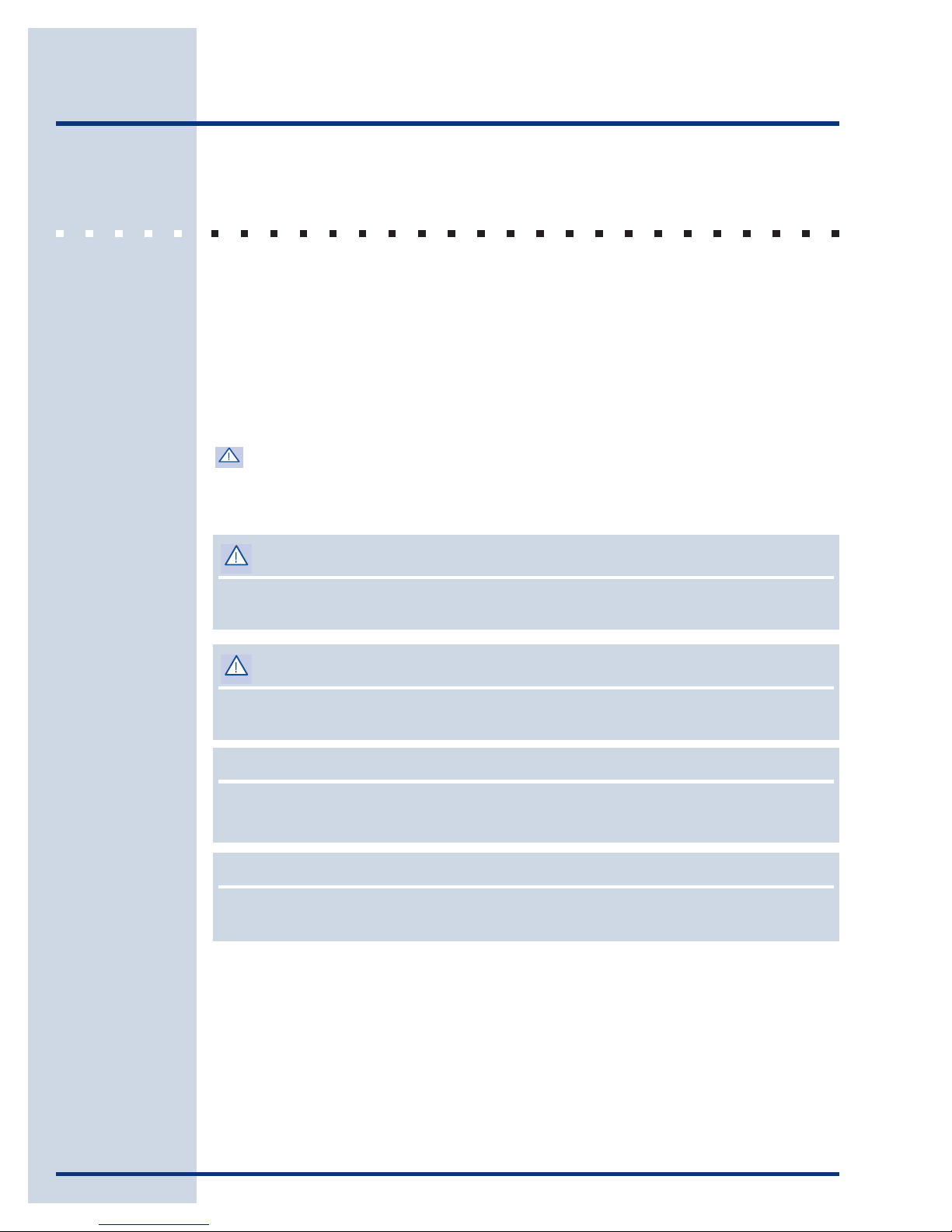
Installation Instructions
Slide In Gas Cooktop
E36GC76EPS E48GC76EPS
5995447108
2
Safety
IMPORTANT SAFETY INSTRUCTIONS
Safety Precautions
Do not attempt to install or operate your unit until you have read the safety
precautions in this manual. Safety items throughout this manual are labeled with a
Warning or Caution based on the risk type.
Definitions
This is the safety alert symbol. It is used to alert you to potential personal
injury hazards. Obey all safety messages that follow this symbol to avoid possible
injury or death.
WARNINGWARNING
WARNING
WARNINGWARNING
WARNING indicates a potentially hazardous situation which, if not avoided, could
result in death or serious injury.
CACA
UTIONUTION
CA
UTION
CACA
UTIONUTION
CAUTION indicates a potentially hazardous situation which, if not avoided, may result
in minor or moderate injury.
CACA
UTIONUTION
CA
UTION
CACA
UTIONUTION
CAUTION used without the safety alert symbol indicates a potentially hazardous
situation which, if not avoided, may result in property damage.
IMPORIMPOR
IMPOR
IMPORIMPOR
Indicates installation, operation or maintenance information which is important but
not hazard related.
TT
ANTANT
T
ANT
TT
ANTANT
Safety
SAFETY PRECAUTIONS
WARNINGWARNING
WARNING
WARNINGWARNING
• Read all instructions before using the appliance.
• Improper installation, adjustment, alteration, service, or maintenance can cause
personal injury or property damage. Refer to these instructions and the
accompanying Use & Care Manual. For assistance or additional information,
consult a qualified installer, service agency, manufacturer (dealer), or the gas
supplier.
• For your safety:
- Do not obstruct the flow of combustion and ventilation air to the unit.
- Keep appliance area clear and free from combustible material, gasoline and
other flammable vapors and liquids.
- Do not use or attempt to use this appliance in the event of a power failure.
• This unit is designed as a cooking appliance. Never use it for warming or heating
a room.
• This appliance must be installed with the gas pressure regulator supplied with it.
• Disconnect the electrical supply before installing or servicing the appliance.
• This appliance must be grounded. Connect only to a properly grounded
electrical supply. Refer to “Electrical Requirements”.
• Install or locate this appliance only in accordance with these installation
instructions.
• Use this appliance only for its intended use as described in this manual. Do not
use corrosive chemicals or vapors in this appliance. This type of appliance is not
designed for industrial or laboratory use.
• As with any appliance, close supervision is necessary when used by children.
• Do not operate this appliance if it has a damaged electrical cord, plug, conduit or
wires, if it is not working properly, or if it has been damaged or dropped.
• This appliance should be installed and serviced only by qualified service
personnel.
• Some products, such as whole eggs, and sealed containers, such as closed glass
jars, may explode and should not be heated on this cooktop.
3

4
Safety
WARNINGWARNING
WARNING
WARNINGWARNING
• Based on safety considerations, the top burner flame should be adjusted so it
does not extend beyond the edge of the cooking utensil.
• If the information in this manual is not followed exactly, a fire or explosion
may result causing property damage, personal injury, or death.
• What to do if you smell gas:
- Do not try to light any appliance.
- Do not touch any electrical switch, do not use any phone in your building.
- Immediately call the gas supplier from a neighbor’s phone.
- Follow the gas supplier’s instructions.
- If you cannot reach your gas supplier, call thefire department.
• For your safety:
- Do not store or use gasoline or other flammable vapors and liquids in the
vicinity of this or any other appliance.
• Installation of this appliance must be performed by a qualified installer, service
agency or the gas supplier. Contact the nearest Electrolux Authorized Servicer,
call 1-877-435-3287, or contact us on the internet at www.electroluxusa.com.

Finding Information
READ AND SAVE THESE INSTRUCTIONS
5
NONO
TETE
NO
TE
NONO
TETE
Installer: Leave instructions with owner.
Owner: Read your cooktop Use & Care Manual. It contains important safety information
for operating this appliance. It also has many suggestions for getting the best results
from your cooktop.
Read all instructions before installing the cooktop.
For your safety, please read and observe all safety instructions. This guide will help
you anticipate all installation connections.
QUESTIONS?
For toll-free telephone support in the U.S. and Canada:
1-877- 4ELECTROLUX (1-877-435-3287)
Attach your sales
receipt to this
page for future
reference.
For online support and Internet product information:
www.electroluxusa.com
©2005 Electrolux Home Products, Inc.
Post Office Box 212378, Augusta, Georgia 30917, USA
All rights reserved. Printed in the USA

6
Finding Information
TABLE OF CONTENTS
Safety..................................................................... 2
Definitions ........................................................... 2
Important Safety Instructions ............................... 2
Safety Precautions .............................................. 3
Finding Information ............................................ 5
Please Read And Save This Guide .................... 5
Questions?.......................................................... 5
Table Of Contents ............................................... 6
Preparing for Installation ................................... 7
Verifying Package Contents ................................ 7
Cabinet/Counterop Preparation.......................... 7
Making the Gas/Electric Connection ............... 11
Requirements ................................................... 11
L.P. Gas Conversion ........................................ 12
Installation.......................................................... 14
Installing the Cooktop ........................................ 14
Connecting the Gas .......................................... 14
Gas and Electric Requirements Table ............... 15
Installing the Burner Components ..................... 16
Making the Electrical Connection ...................... 17
Operation ............................................................ 18
Verifying the Operation...................................... 18
Preparing for Installation
VERIFY PACKAGE CONTENTS
• Literature Pack • Griddle
• Bolts/Washers • Simmer Plate
• Burner Grate Pack • Wok Stand
• Burner Set • Stainless Steel Cleaner
• Gas Pressure Regulator • LP Conversion Kit
• Burner Cap Pack
CABINET/COUNTERTOP PREPARATION
The installation of this built-in appliance must be completed by a qualified appliance
technician or contractor. Proper installation is the owner’s responsibility.
7
Carefully check the location where the cooktop is to be installed. The cooktop
should be placed for convenient access, but away from drafts that may be caused
by open doors and windows or by HVAC duct outlets. Make certain that gas and
electrical power can be provided in the selected locations. Plan the installation so
that all minimum clearances are met or exceeded. Dimensions shown provide
minimum clearances, unless otherwise noted.
WARNINGWARNING
WARNING
WARNINGWARNING
• To reduce the risk of personal injury caused by reaching over a hot appliance,
cabinet storage space located directly above the cooktop should be avoided.
• Keep appliance area clear and free from combustible materials, gasoline and
other flammable vapors and liquids.
• Failure to provide proper clearances may result in a fire hazard!
• Do not store combustible materials or items adversely affected by heat
immediately above or below the cooktop.
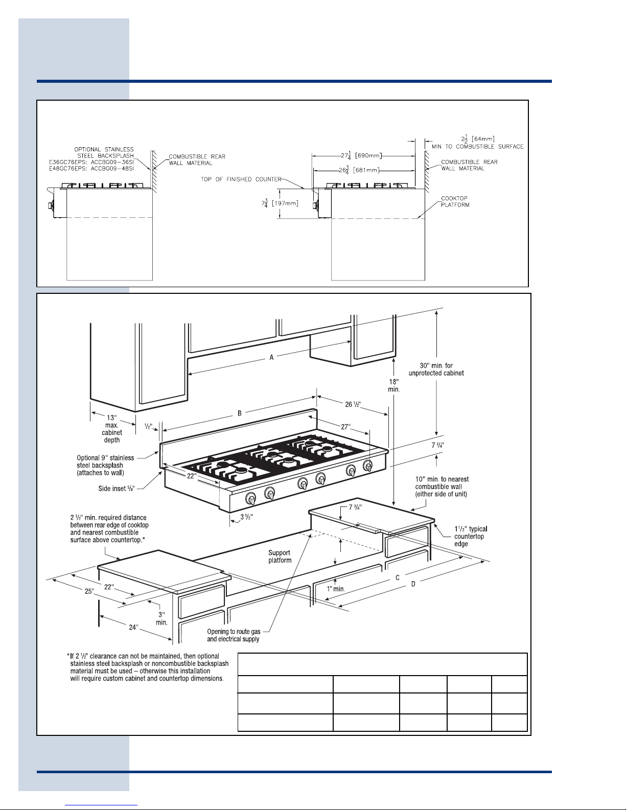
• The back edge of the cooktop must remain a minimum of 2 1/2" (64mm) from any
combustible backsplash material. This will require special cabinet and
countertop dimensions. Installations with less than 2 1/2” from the rear of the
cooktop to a combustible backsplash must use Electrolux Backsplash models
ACCBG096S1 (for E36GC76EPS) or ACCBG0948S1 (for E48GC76EPS).
8
Preparing for Installation
Figure 1
10" (254mm)
Min. to
combustible side
wall, both sides
IMPORIMPOR
IMPOR
IMPORIMPOR
TT
ANTANT
T
ANT
TT
ANTANT
• When installing the cooktop into a laminated (Formica, etc.) or synthetic (Corian,
etc.) countertop, radius the corners of the cutout to prevent cracking of the
countertop.
• Follow the countertop manufacturer’s instructions regarding the minimum corner
radius, use of heat reflective tape, reinforcement of corners, etc.
• If cabinet storage space is to be provided directly above the cooktop, the risk of
personal injury may be reduced by installing a ventilating hood that projects
horizontally a minimum of 5 inches beyond the face of the cabinets.
• Both models are designed to allow installation in standard 24 inch deep base
cabinets with 25 inch overall depth countertops. Deeper cabinets and
countertops may be used to provide required clearances to combustible rear wall
materials or for design purposes.
• The specified cabinet dimensions must be provided. The cabinet and/or
countertop must completely enclose the recessed portion of the countertop.
All contact surfaces between the appliance and the countertop must be solid
and level.
Plan the installation so that the electrical connection, gas shut-off valve, and
pressure regulator are accessible from the front of the cabinet and so that all of the
minimum required
E36GC76EPS: 42" (1067mm) Recommended
36" (914mm) Minimum
E48GC76EPS: 54" (1372mm) Recommended
E36GC76EPS: 36” (914mm) Minimum
48" (1219mm) Minimum
E48GC76EPS: 48” (1219mm) Minimum
dimensions are provided.
Dimensions apply to both
models unless otherwise
stated (see Figure 1). Locate
Hood
the electrical supply box
within reach of the included
48 inch long flexible cord so
the connection is accessible
when the cooktop is in place.
30" (762mm)
5/8" (16mm) Overhang, both sides
1 1/2" (38mm)
Typical Countertop
18"
(457mm)
Minimum
Cooktop opening
E36GC76EPS: 36" (914mm)
E48GC76EPS: 48" (1219mm)
6"
(152mm)
C
L
Utilities
Location
E36GC76EPS:
24" (610mm)
E48GC76EPS: 30" (762mm)
7 3/4"
(197mm)
15 1/2"
(393mm)
10"
(254mm)
28 1/4"
(717mm)
36"
(914mm)
Preparing for Installation
9
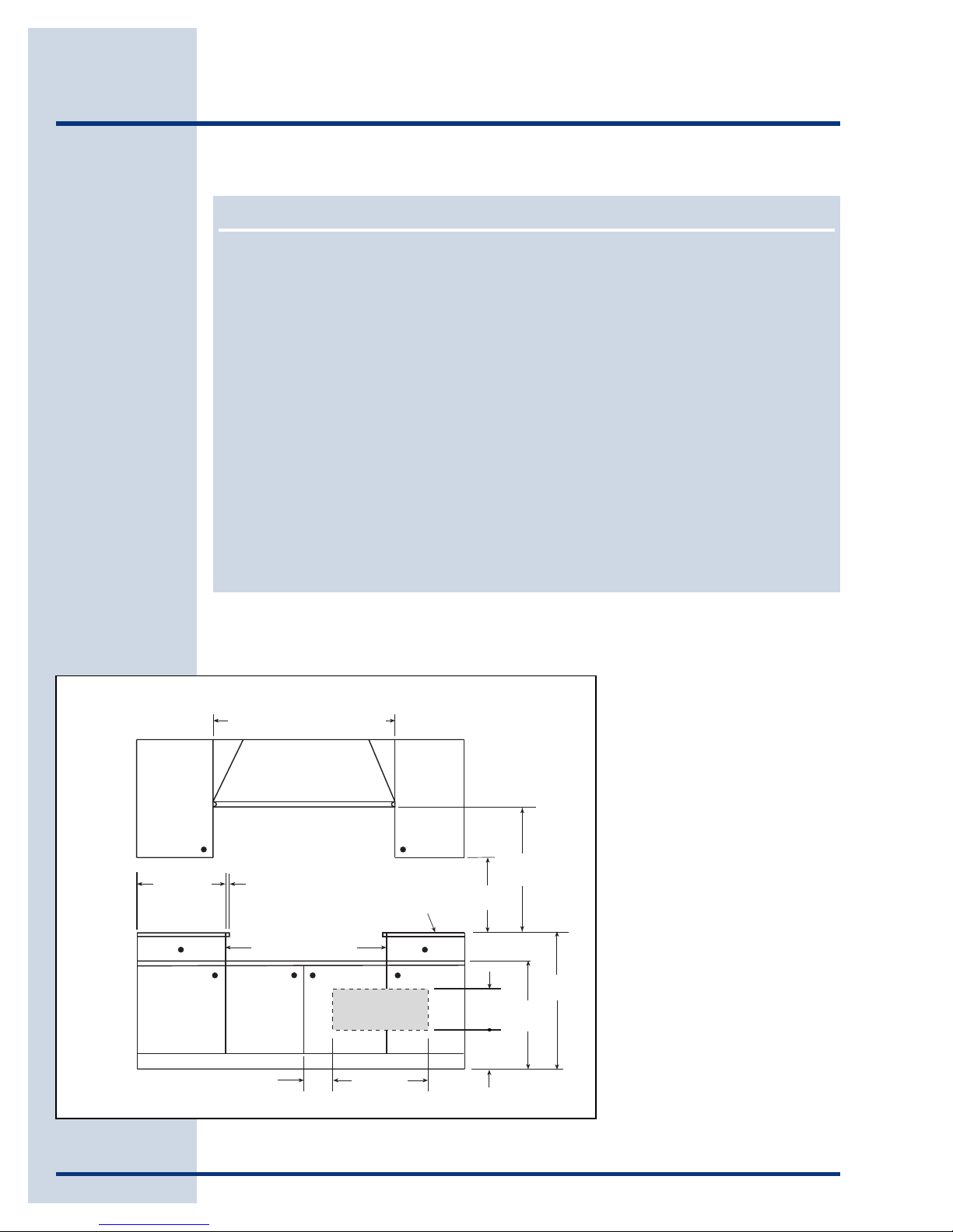
Provide an opening in the countertop
as shown (see Figures 2, 3, 4, 5
and 6). Position the cutout so that
minimum clearances are met.
Base Cabinet Preparation
Countertop Preparation
Top View
Figure 2
Figure 3
(when Cooktop is to be installed with Downdraft Vent Hood
Countertop Cut-out Dimensions
36” model: E36DD75ESS; 48” model: E48DD75SS)
Figure 4
10
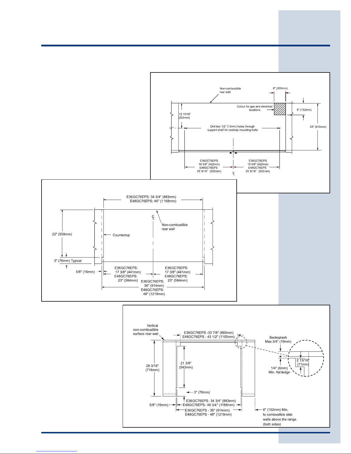
Preparing for Installation
Overall Dimensions - Side Views
Clearance to Combustible Rear Wall
Figure 5
Overall Dimensions
Cutout Dimensions
Clearance to Combustible Rear Wall
Figure 6
Dimensions
Cooktop Model A B C D
E48GC76EPS 48” Min. 48” 46” 48”
E36GC76EPS 36” Min. 36” 34¾” 36”
 Loading...