

Page 1
Installation InstructionsInstallation Instructions
Installation Instructions
Installation InstructionsInstallation Instructions
Retractable Ventilation System
Instrucciones de Instalación
Sistema de ventilación retráctil
Instructions d’installationInstructions d’installation
Instructions d’installation
Instructions d’installationInstructions d’installation
Système de ventilation rétractable
Dishwasher
E30DD75ESS E36DD75ESS E46DD75ESS E48DD75ESS
5995426227
Page 2

2
Finding Information
READ AND SAVE THESE INSTRUCTIONS
Attach your sales
receipt to this
page for future
reference.
NONO
TETE
NO
TE
NONO
TETE
Installer: Leave instructions with owner.
Owner: Read your Retractable Ventilation System Use & Care Manual. It contains
important safety information for operating this appliance. It also has many suggestions
for getting the best results from your downdraft vent.
Read all instructions before installing the downdraft vent.
For your safety, please read and observe all safety instructions. This guide will help
you anticipate all installation connections.
QUESTIONS?
For toll-free telephone support in the U.S. and Canada:
1-877- 4ELECTROLUX (1-877-435-3287)
For online support and Internet product information:
www.electroluxusa.com
©2004 Electrolux Home Products, Inc.
Post Office Box 212378, Augusta, Georgia 30917, USA
All rights reserved. Printed in the USA
Page 3

Finding Information
TABLE OF CONTENTS
Finding Information ........................................... 2
Please Read And Save This Guide ................... 2
Questions .......................................................... 2
Table Of Contents .............................................. 3
Safety ................................................................... 4
Important Safety Instructions .............................. 4
Safety Precautions ............................................. 5
Preparing for Installation .................................. 7
Verifying Package Contents ............................... 7
Installation Planning ........................................... 7
Specifications and Dimensions ........................... 8
Electrical Power Supply ..................................... 9
Requirements .................................................... 9
3
Duct Preparation ............................................... 10
Duct Installation ................................................ 10
Countertop Preparation ................................... 13
Preparing the Countertop ................................ 13
Installation ........................................................ 16
Installing the Downdraft Vent ............................ 16
Connecting the Exhaust Duct ........................... 16
Making the Electrical Connection ..................... 17
Installing with a Cooktop/Range ....................... 18
Operation ........................................................... 19
Verifying the Operation .................................... 19
Page 4
4
Safety
IMPORTANT SAFETY INSTRUCTIONS
Safety Precautions
Do not attempt to install or operate your unit until you have read the safety
precautions in this manual. Safety items throughout this manual are labeled with a
Warning or Caution based on the risk type.
Definitions
!
This is the safety alert symbol. It is used to alert you to potential personal injury
hazards. Obey all safety messages that follow this symbol to avoid possible injury
or death.
!
WARNINGWARNING
WARNING
WARNINGWARNING
WARNING indicates a potentially hazardous situation which, if not avoided, could
result in death or serious injury.
!
CACA
UTIONUTION
CA
UTION
CACA
UTIONUTION
CAUTION indicates a potentially hazardous situation which, if not avoided, may result
in minor or moderate injury.
CACA
UTIONUTION
CA
UTION
CACA
UTIONUTION
CAUTION used without the safety alert symbol indicates a potentially hazardous
situation which, if not avoided, may result in property damage.
IMPORIMPOR
IMPOR
IMPORIMPOR
Indicates installation, operation or maintenance information which is important but
not hazard related.
TT
ANTANT
T
ANT
TT
ANTANT
Page 5

Safety
5
SAFETY PRECAUTIONS
!
WARNINGWARNING
WARNING
WARNINGWARNING
• To reduce the risk of fire, electric shock, or injury to persons, observe the following:
a) Installation work and electrical wiring must be done by qualified person(s) in
accordance with all applicable codes and standards, including fire-rated
construction.
b) Sufficient air is needed for proper combustion and exhausting of gases
through the flue (chimney) of fuel burning equipment to prevent back
drafting. Follow the heating equipment manufacturer’s guidelines and safety
standards such as those published by the National Fire Protection
Association (NFPA), and the American Society for Heating, Refrigeration and
Air Conditioning Engineers (ASHRAE), and the local code authorities.
c) When cutting or drilling into wall or ceiling, do not damage electrical wiring
and other hidden utilities.
d) Ducted fans must always be vented outdoors.
e) Use this unit only in the manner intended by the manufacturer. If you have
questions, contact the manufacturer.
• To reduce the risk of fire, use only metal ductwork.
• Grounding Instructions
This appliance must be grounded. In the event of an electrical short circuit,
grounding reduces the risk of electric shock by providing an escape wire for the
electric current. This appliance is equipped with a cord having a grounding wire
with a grounding plug. The plug must be plugged into an outlet this is properly
installed and grounded.
• Improper grounding can result in a risk of electric shock.
• Consult a qualified electrician if the grounding instructions are not completely
understood, or if doubt exists as to whether the appliance is properly grounded.
• Do not use an extension cord. If the power supply cord is too short, have a
qualified electrician install an outlet near the appliance.
Page 6

6
Safety
!
CACA
UTIONUTION
CA
UTION
CACA
UTIONUTION
To reduce the risk of fire and electric shock, install this retractable ventilation unit only
with remote blower models rated maximum 8 amp (total of all interconnected remote
blowers).
Page 7

Preparing for Installation
VERIFY PACKAGE CONTENTS
• Use & Care Guide
• Anchoring Legs and Hardware
INSTALLATION PLANNING
A qualified technician must complete the installation of this appliance. Proper
installation is your responsibility.
Sufficient air is needed for proper combustion and exhausting of gases through the
flue (chimney) of fuel burning equipment to prevent back drafting. Follow the
heating equipment manufacturer’s guideline and safety standards such as those
published by he national Fire Protection Association (NFPA), and the American
Society for Heating, Refrigeration and Air Conditioning Engineers (ASHRAE), and
the local code authorities.
7
Plan the installation so that all required minimum clearances between the cooktop,
overhead cabinets and adjacent vertical walls are provided. Refer to the cooktop/
range installation instructions for the minimum dimensions specific to the particular
appliance being installed.
The vent system is designed to remove the contaminants and by-products that
result when cooking with gas or electric appliances. The vent system consists of
the vent intake along with a remote blower. The raised vent downdraft systems are
compatible for use with select cooktops and ranges, therefore, these instructions
offer specific guidelines for mounting the raised vents behind cooktops and ranges.
Make sure that you have everything needed to complete the installation
before proceeding.
Page 8
8
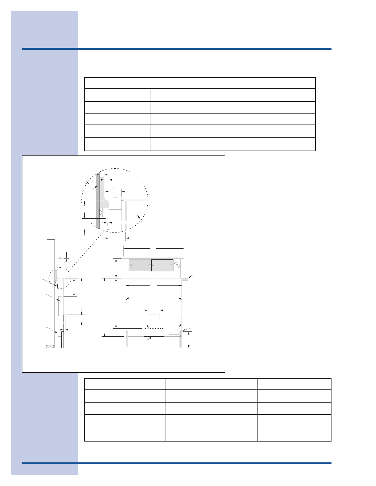
Specifications and Dimensions
Raised Vent System Specifications
Stiffener
1 5/8" x 16"
Exhaust duct
3 1/4" x 10"
Exhaust duct
3/8"
(10mm)
Stud wall
6 5/8"
(168mm)
3/4" (19mm)
Raised Vent Model No.
E30DD75ESS
E36DD75ESS
E46DD75ESS
E48DD75ESS
3/4" (19mm) Max. backsplash thickness
1/4" (6mm) Min. flat area
Wall board
(76mm)
1 15/16"
(49mm)
22 1/2"
(572mm)
3 3/4"
(95mm)
3"
Finished floor
30"
(762mm)
2 1/8"
(54mm)
9/32" (7mm)
2 13/16"
(71mm)
10"
(254mm)
25 7/8"
(657mm)
1 5/8" x 16"
Exhaust duct
3 1/4" x 10"
Rear
Exhaust duct
1 5/8" x 16"
Exhaust duct
For Use With Gas Cooktops Duct Size
E30GC64ESS
E36GC65ESS
E46GC66ESS/E46GC67ESS
E46GC66ESS/E46GC67ESS
Cooktop/Range
A
Countertop
B
1 5/8" x 16"
Exhaust duct
6"
(152mm)
Motor
cover
Electrical
access panel
48", 3 prong grounded
8 1/2"
(216mm)
power cord
3 1/4”x10” & 10”
3 1/4”x10” & 10”
3 1/4”x10” & 10”
3 1/4”x10” & 10”
Figure 1
Model
E30DD75ESS
E36DD75ESS
E46DD75ESS
E48DD75ESS 48” (1219mm) 43 3/8” (1102mm)
Width “A” Width “B”
30” (762mm) 27 3/4” (705mm)
36” (914mm)
33 3/4” (857mm)
46” (1168mm) 43 3/8” (1102mm)
Page 9
Electrical Power Supply
REQUIREMENTS
!
WARNINGWARNING
WARNING
WARNINGWARNING
Failure to disconnect power may result in electrical shock or fire hazard! If the
electric service provided does not meet the product specifications, do not
proceed with the installation. Call the selling dealer or a licensed electrician.
It is the owner’s responsibility to ensure that the electrical connection of this
appliance is performed by a qualified electrician. The electrical installation,
including minimum supply wire size and grounding, must be in accordance with the
National Electric code ANSI/NFPA 70-1993* (or latest revision) and local codes and
ordinances.
A copy of this standard may be obtained from:
9
National Fire Protection Association
1 Batterymarch Park
Quincy, Massachusetts 02269-9101
The correct 120VAC, 60Hz, 15A circuit must be supplied for this appliance from a
separate, grounded, circuit that is protected by a properly sized circuit breaker or
time delay fuse.
Page 10

10
Duct Preparation
DUCT INSTALLATION
!
WARNINGWARNING
WARNING
WARNINGWARNING
• To reduce the risk of fire and to properly exhaust air, ducted fans must be vented
to outside. Do not vent exhaust air into spaces within walls, ceilings, attics, crawl
spaces or garages.
• Improper installation, adjustment, alteration, service, or maintenance can cause
personal injury or property damage.
• To reduce the risk of fire, use only duct work materials deemed acceptable by
state, municipal and local codes.
IMPORIMPOR
IMPOR
IMPORIMPOR
• Best performance is achieved by using round duct instead of rectangular,
especially when elbows are required.
• If multiple elbows are needed, ensure that there is a minimum of 24” of straight
duct between any two elbows.
• Avoid “S” or “back to back” configurations caused by adjacent elbows.
• Thermal breaks, such as a short section of non-metallic duct, should be used in
areas of extreme cold.
• A back-draft damper at the duct outlet may also be required.
• Do not use flexible metal duct.
• Do not use duct work that is smaller in cross-sectional area than the
recommended size duct.
• Do not rely on duct tape alone to seal duct joints. Use sheet metal screws as
require to support the duct weight.
• The vent hood and cooking appliance(s) must be removable if service is required.
• Be certain that the duct work does not interfere with floor joists or wall studs.
• It is important to keep a minimum number of turns in the duct run, and to keep the
run as short as possible.
• Do not restrict the air flow by reducing the duct cross-sectional areas when
making hard joints or squeezing through a tight area.
• With concrete slab construction, “box-in” the duct work to prevent it from
collapsing when the wet concrete is poured. Also allow room for electrical
conduit.
• Cross-drafts or air currents caused by adjacent open windows or doors, HVAC
outlets, and ceiling fans reduce vent efficiency.
TT
ANTANT
T
ANT
TT
ANTANT
Page 11

Duct Preparation
3 1/4" x 10" 90° Elbow 3 1/4" x 10" 45° Elbow 3 1/4" x 10" Wall Cap 3 1/4" x 10"
90° Flat Elbow
Transistion
3 1/4" x 10" to Round
45° Elbow - Round Duct 90° Transistion
3 1/4" x 10" to 10" Round
90° Elbow - Round Duct
15 Feet 7 Feet 2 Feet 20 Feet
10" Diameter - 4 Feet
10" Diameter - 2 Feet
25 Feet
10" Diameter - 5 Feet
Higher volumes of air exhausted by the vent system result in better overall removal
of smoke and fumes from the kitchen. Longer duct runs and greater numbers of
duct transitions reduce air volume, therefore it is extremely important to keep
duct runs as short and straight as possible.
Maximum Equivalent Straight LengthsModel Duct
Size
11
E30DD75ESS
E36DD75ESS
E46DD75ESS
E48DD75ESS
10”
3 1/4” x 10” 60’
70’
We recommend using a certified HVAC contractor for all installations.
To ensure that your installation
meets this requirement, add the
actual straight length of duct to the
equivalent straight length of all duct
fittings to determine the total
equivalent straight length of duct.
(Refer to the table on the right,
which shows various common duct
fittings with their equivalent straight
lengths for various common duct
sizes). If this total equivalent
straight length is less than or equal
to the maximum limits specified,
then the installation is proper.
Consider the duct size that
corresponds to the majority of the duct used in the installation.
Sample problem - for reference only:
Given a system installation having 25 feet of 3 ¼” x 10” rectangular duct, one (1)
90-degree 3 ¼” x 10” elbow, and one (1) 3 ¼” x 10” to 10” round transition, would
this installation be proper?
Solution:
1. Add the total length of straight duct:
25’ (of 3 ¼” x 10”) = 25’.
2. Using Table above, determine the equivalent straight length of all duct fittings:
90-degree 3 ¼” x 10” elbow = 15’. 3 ¼” x 10” to 10” round transition = 4’.
Page 12

12
Duct Preparation
3. Add (1) and (2) to determine the total equivalent straight length of the
complete duct system: 25’ + 15’ + 4’ = 44’ total equivalent straight duct length.
4. For the system with 3 ¼” x 10” duct, the maximum allowable total equivalent
straight length of duct is 60 feet. Thus, this proposed installation is proper.
After determining that your proposed duct work meets the maximum duct length
requirement, proceed with the location planning.
Page 13

Countertop Preparation
13
PREPARING THE COUNTERTOP
!
WARNINGWARNING
WARNING
WARNINGWARNING
• To reduce the risk of personal injury caused by reaching over a hot appliance,
cabinet storage space located directly above the cooktop should be avoided.
• Do not store combustible materials or items adversely affected by heat in cabinet
areas above the appliance.
• Follow the instructions regarding minimum safe clearances and installation
location. Failure to do so may result in a fire or safety hazard.
Plan the installation so that all required minimum clearances between the cooktop,
overhead cabinets and adjacent vertical walls are provided. Refer to the cooktop
installation instructions for the minimum dimensions specific to the particular
appliance being installed.
The raised vent system is designed to remove the contaminants and by-products
that result when cooking with gas or electric appliances. The vent system consists
of the vent intake along with a remote blower. The raised vent downdraft systems
are compatible for use with select cooktops, therefore, these instructions offer
specific guidelines for mounting the raised vents behind the cooktops.
IMPORIMPOR
IMPOR
IMPORIMPOR
Verify that the raised vent and blower being installed are a matched pair before
beginning the installation. (Part number 5304444802 and E30DD75ESS, E36DD75ESS,
E46DD75ESS, and E48DD75ESS.)
For installation of the raised vent system, provide an opening in the countertop as
shown in the Countertop Preparation section. Position the cutout so all required
minimum clearances are met. Make certain that the minimum flat countertop area
meets or exceeds the combined overall width and overall depth, as shown in
Figures 2, 3 and 4 that follow.
TT
ANTANT
T
ANT
TT
ANTANT
Page 14

14
Countertop Preparation
Electrolux Icon Model No.
E30GC64ESS
Cutout “A” Cutout “B”
27 1/2” (698 mm) -
E30EC65ESS 30” (762 mm) 27 1/2” (698 mm)
E36GC65ESS
33 3/4” (857 mm)
E36EC65ESS 36” (914 mm) 33 3/4” (857 mm)
E46GC66ESS
E46GC67ESS 44 1/2” (1130 mm)
Vertical
non-combustible
surface rear wall
25"
(635mm)
23 1/4"
(591mm)
Min.
22 7/16"
(570mm)
44 1/2” (1130 mm)
Figure 2
Flush with
backside of
cabinet front
Backsplash
Max.3/4" (19mm)
1/4" (6mm)
Min. flat ledge
43 1/2” (1105 mm)
43 1/2” (1105 mm)
-
25"
(635mm)
Vertical
non-combustible
surface rear wall
23 1/4"
(591mm)
Min.
A
Overall Cutout Dimensions
(E30GC64ESS and E36GC65ESS)
Figure 3
B
20 3/8"
(508mm)
Flush with
backside of
cabinet front
A
Overall Cutout Dimensions
(E30EC65ESS and E36EC65ESS)
7 1/2" (191mm) Min.
to combustible side
walls above the range
(both sides)
Backsplash
Max.3/4" (19mm)
1/4" (6mm)
Min. flat ledge
7 1/2" (191mm) Min.
to combustible side
walls above the range
(both sides)
2 9/16"
(65mm)
Page 15

Countertop Preparation
Figure 4
Vertical
non-combustible
25"
(635mm)
surface rear wall
23 1/4"
(591mm)
Min.
19 7/8"
(505mm)
B
Flush with
backside of
cabinet front
Backsplash
Max.3/4" (19mm)
1/4" (6mm)
Min. flat ledge
2 9/16"
(65mm)
15
A
Overall Cutout Dimensions
(E46GC66ESS and E46GC67ESS)
7 1/2" (191mm) Min.
to combustible side
walls above the range
(both sides)
Page 16

16
Installation
INSTALLING THE DOWNDRAFT VENT
IMPORIMPOR
IMPOR
IMPORIMPOR
The vent must be installed in a vertical orientation. Do not mount the vent on a slant or
angle.
Remove the knockout from the plenum by cutting the tape and metal cross overs to
remove the insert.
Loosely attach the anchoring legs to the left and right sides of the plenum using the
hex nuts provided. Place the vent into the rear of the countertop cutout. Adjust the
anchoring leg height so that the end caps are gently resting on the counter, then
tighten the hex nuts. Secure the anchoring legs to the cabinet/floor with the screws
provided.
TT
ANTANT
T
ANT
TT
ANTANT
CONNECTING THE EXHAUST DUCT
IMPORIMPOR
IMPOR
IMPORIMPOR
TT
ANTANT
T
ANT
TT
ANTANT
Use duct tape and sheet metal screws to seal the connection between the blower outlet
and duct. Support the duct weight as necessary to ensure sealed joints.
For the side or bottom knockouts use the supplied transition. For the rear knockout
attach a 3 1/4" x 10" duct.
Page 17

Installation
17
MAKING THE ELECTRICAL CONNECTION
!
WARNINGWARNING
WARNING
WARNINGWARNING
• Ensure that the power supply is disconnected before proceeding.
• Verify that the power supply matches the ratings found on the appliance data
plate before proceeding.
• The complete appliance must be properly grounded at all times when electrical
power is applied.
• Do not ground the appliance with the neutral (white) house supply wire. A
separate ground wire must be utilized.
• If aluminum house supply wiring is used, splice the appliance copper wires to the
aluminum house wiring with special connectors designed and agency-certified
for this purpose. Follow the connector manufacturer’s recommended procedure
carefully. Improper connection can result in a fire hazard.
• Failure to complete electrical connections properly may result in a damaged or
nonfunctional system. Follow the wiring diagrams carefully to ensure a proper
installation.
Both vent systems require a properly
grounded, 120 VAC, 60 Hz., 15 Amp
electrical service. Maximum full line
load is 8 amps. Always use a
dedicated circuit. Do not use same
circuit that the cooktop is using.
Make all electrical connections
between the vent and blowers, then
connect power to the vent as per the
wiring diagrams. Use wire nuts
provided and electrical tape to secure
all wiring connections at the blowers.
See wiring diagram in Figure 5.
RVS
GRN
GRN
WHT
BLK
WHT
BLK
Figure 5
Blower
Wiring of RVS
GRN
WHT
BLK
with B
120VAC, 60Hz, 15A
48” (1219mm) power cord with
three prong grounded plug
BLK
WHT
GRN
l
owe
r
Page 18

18
Installation
INSTALLING WITH A COOKTOP
!
WARNINGWARNING
WARNING
WARNINGWARNING
• The cooktops have very different installation requirement. Please make sure you
read the Installation Instructions for the accompanying cooktop thoroughly
before continuing the installation process.
• After the cooktop has been installed ensure that the top cap on the vent intake
does not catch on the back edge of the cooktop when the intake is lowered. If
interference does occur, adjust the position of the cooktop by moving it against
the front edge of the countertop cutout, then re-secure the cooktop to the
countertop. Also, ensure that the vent anchoring legs have been properly
secured to the cabinet base using the screws provided in the instructions
envelope. Failure to eliminate interference may result in permanent damage to the
vent.
Page 19

Operation
19
VERIFYING THE OPERATION
!
WARNINGWARNING
WARNING
WARNINGWARNING
• If the vent system is not operational after completion of the installation, do not
attempt to repair it. See the Problem Solving section of the Use & Care Guide, then
call a qualified service technician if the system is still not functional.
• Always disconnect the appliances from the electrical power when servicing them.
• Install the two (2) front filters and the grill prior to operating the vent. Refer to the
Use & Care Guide for instructions regarding filter and grill installation.
• Press the top cap up/down switch once to raise the vent to its operating
position.
• In the up position, turn the variable speed control switch in both directions
to verify that the blower is operating correctly.
• Press the top cap up/down switch once to lower the vent.
Page 20

Installation InstructionsInstallation Instructions
Installation Instructions
Installation InstructionsInstallation Instructions
External Blower Assembly for
Electrolux Retractable Ventilation Systems
Dishwasher
E30DD75ESS E36DD75ESS E46DD75ESS E48DD75ESS
5995433678
Page 21

2
Safety
IMPORTANT SAFETY INSTRUCTIONS
Safety Precautions
Do not attempt to install or operate your unit until you have read the safety
precautions in this manual. Safety items throughout this manual are labeled with a
Warning or Caution based on the risk type.
Definitions
!
This is the safety alert symbol. It is used to alert you to potential personal injury
hazards. Obey all safety messages that follow this symbol to avoid possible injury
or death.
!
WARNINGWARNING
WARNING
WARNINGWARNING
WARNING indicates a potentially hazardous situation which, if not avoided, could
result in death or serious injury.
!
CACA
UTIONUTION
CA
UTION
CACA
UTIONUTION
CAUTION indicates a potentially hazardous situation which, if not avoided, may result
in minor or moderate injury.
CACA
UTIONUTION
CA
UTION
CACA
UTIONUTION
CAUTION used without the safety alert symbol indicates a potentially hazardous
situation which, if not avoided, may result in property damage.
IMPORIMPOR
IMPOR
IMPORIMPOR
Indicates installation, operation or maintenance information which is important but
not hazard related.
TT
ANTANT
T
ANT
TT
ANTANT
Page 22

Safety
3
SAFETY PRECAUTIONS
!
WARNINGWARNING
WARNING
WARNINGWARNING
• To reduce the risk of fire, electric shock, or injury to persons, observe the following:
a) Installation work and electrical wiring must be done by qualified person(s) in
accordance with all applicable codes and standards, including fire-rated
construction.
b) Sufficient air is needed for proper combustion and exhausting of gases
through the flue (chimney) of fuel burning equipment to prevent back
drafting. Follow the heating equipment manufacturer’s guidelines and safety
standards such as those published by the National Fire Protection
Association (NFPA), and the American Society for Heating, Refrigeration and
Air Conditioning Engineers (ASHRAE), and the local code authorities.
c) When cutting or drilling into wall or ceiling, do not damage electrical wiring
and other hidden utilities.
d) Ducted fans must always be vented outdoors.
e) Use this unit only in the manner intended by the manufacturer. If you have
questions, contact the manufacturer.
f) Before servicing or cleaning unit, switch power off at service panel and lock
the service disconnecting means to prevent power from being switched on
accidentally. When the service disconnecting means cannot be locked,
securely fasten a prominent warning device, such as a tag, to the service
panel.
g) Blower must not be installed in a ceiling thermally insulated to a value
greater than R40.
h) Blower must not be installed in furnace ductwork.
• To reduce the risk of fire, use only metal ductwork.
Page 23

4
Safety
SAFETY PRECAUTIONS
!
WARNINGWARNING
WARNING
WARNINGWARNING
• To reduce the risk of a range top grease fire:
a) Never leave surface units unattended at high settings. Boilovers cause
smoking and greasy spillovers that may ignite. Heat oils slowly on low or
medium settings.
b) Always turn hood ON when cooking at high heat or when flambeing food (i.e.
Crepes Suzette, Cherries Jubilee, Peppercorn Beef Flambe’).
c) Clean ventilating fans frequently. Grease should not be allowed to accumulate
on fan or filter.
d) Use proper pan size. Always use cookware appropriate for the size of the
surface element.
• To reduce the risk of injury to persons in the event of a range top grease fire,
observe the following:
a) SMOTHER FLAMES with a close-fitting lid, cookie sheet, or metal tray, then
turn off the burner. BE CAREFUL TO PREVENT BURNS. If the flames do not go
out immediately, EVACUATE AND CALL THE FIRE DEPARTMENT.
b) NEVER PICK UP A FLAMING PAN - You may be burned.
c) DO NOT USE WATER, including wet dishcloths or towels - a violent steam
explosion will result.
d) Use an extinguisher ONLY if:
1) You know you have a Class ABC extinguisher, and you already know how to
operate it.
2) The fire is small and contained in the area where it started.
3) The fire department is being called.
4) You can fight the fire with your back to an exit.
Page 24

Safety
5
SAFETY PRECAUTIONS
!
CACA
UTIONUTION
CA
UTION
CACA
UTIONUTION
• For general ventilating use only. Do not use to exhaust hazardous or explosive
materials and vapors.
• To reduce risk of fire and to properly exhaust air, be sure to duct air outside – Do
not vent exhaust air into spaces within walls or ceilings or into attics, crawl spaces
or garages.
• This blower assembly is approved for use with the following Electrolux retractable
ventilation systems: E30DD75ESS, E36DD75ESS, E46DD75ESS and E48DD75ESS
only. Use of this blower assembly with any other product or in any other
configuration is hazardous and voids the product warranty.
NONO
TESTES
NO
TES
NONO
TESTES
• Consult a licensed ventilation contractor or qualified technician for proper
installation of exhaust ducting.
• Locate the cooking area for minimum cross drafts – away from doors and windows,
when possible.
• Ducts must be of adequate size and duct runs should be as short and straight as
possible. Where turns are necessary, keep turning radius as large and smooth as
possible.
• The ducting must be air tight. Use a minimum of 2 sheet metal screws at every duct
joint. Then, seal the duct joints with a high quality duct tape.
• In duct runs less than 10 equivalent straight feet, the remote blower may interfere
with the cooktop burner performance due to the high volume of air moved. An
adjustable damper (not included) should be installed in the ducting system. The
damper can be adjusted so that proper ventilation and cooktop burner
performance is achieved.
• Installation of duct work should be carefully planned if it is to go under a concrete
slab floor. The duct trench should be boxed to prevent collapse from the wet
cement. Be sure to allow room to run the electrical wiring and conduit.
Page 25

6
Finding Information
READ AND SAVE THESE INSTRUCTIONS
Attach your sales
receipt to this
page for future
reference.
NONO
TETE
NO
TE
NONO
TETE
Installer: Leave instructions with owner.
Owner: Read your Retractable Ventilation System Use & Care Manual. It contains
important safety information for operating this appliance. It also has many suggestions
for getting the best results from your retractable ventilation system.
Read all instructions before installing the retractable vent.
For your safety, please read and observe all safety instructions. This guide will help
you anticipate all installation connections.
QUESTIONS?
For toll-free telephone support in the U.S. and Canada:
1-877- 4ELECTROLUX (1-877-435-3287)
For online support and Internet product information:
www.electroluxusa.com
©2005 Electrolux Home Products, Inc.
Post Office Box 212378, Augusta, Georgia 30917, USA
All rights reserved. Printed in the USA
Page 26

Finding Information
TABLE OF CONTENTS
Safety ................................................................... 2
Important Safety Instructions .............................. 2
Safety Precautions ............................................. 3
Finding Information ........................................... 6
Please Read And Save This Guide ................... 6
Questions .......................................................... 6
Table of Contents ............................................... 7
Planning for Installation .................................... 8
Installation Planning ........................................... 8
Specifications and Dimensions ........................... 8
Making the Electrical Connection ................... 13
Blower Installation ........................................... 14
Verifying Operation .......................................... 14
7
Page 27

8
r
Planning for Installation
INSTALLATION PLANNING
A qualified technician must complete the installation of this appliance.
Carefully check the location where the remote blower is to be installed. The remote
blower should be placed for convenient access. Make certain that electrical power
can be provided in the selected location.
Plan the installation so that all minimum clearances are met or exceeded.
Dimensions shown provide minimum clearances, unless otherwise noted.
SPECIFICATIONS AND DIMENSIONS
NONO
NO
NONO
All dimensional tolerances are + 1/16”, - 0” unless otherwise stated.
Before commencing installation, remove the top cover of the remote blower. Check to
see if the blower wheel turns freely. Do not replace the top cover until the installation is
complete.
Blower Overall Dimensions
Top View
26" (660mm)
24" (610mm)
12 11/16" (322mm)
CLC
L
Power Supply
Conduit
Location
31 1/2"
(800mm)
33 1/2"
(851mm)
Cutout
Location
Discharge
TETE
TE
TETE
9 1/2"
(241mm)
C
C
Intake Collar
Blower Overall Dimensions
Side View
11 1/2"
(292mm)
9 9/16"
(243mm)
3 1/2"
(89mm)
L
L
12 1/4"
(311mm)
Mounting
Flange
Discharge
10"
(254mm)
Intake Colla
Figure 1
Figure 2
Page 28

Planning for Installation
Blower Overall Dimensions
9
Model
No.
5304444802 26” (660mm) 9 9/16” (243mm) 10” (254mm)
Model
No.
5304444802 1600
* The CFM Fan Rating is valued at 0” (zero-inch) static pressure.
Overall Chassis
Width
Electrical
Supply
Requirements
Refer to
Ventilator
Specifications
Maximum
Duct
Length
Max. 60
Equivalent
Straight Feet
Overall Chassis
Height
Blower Specifications
Total
Connected
Load
Fan
Rating*
CFM
Overall Chassis
Length
33 1/2” (851mm)
Approx.
Shipping
Weight
55 lbs.0.3kW (3A)
Duct
Diameter
Finish
Galvanized
(may be painted)
Page 29

10
Planning for Installation
NONO
TETE
NO
TE
NONO
TETE
The blower must be sealed between the roof or wall and the underside of the flange with
mastic to prevent leaks. For installation on a flat roof, or a roof with a pitch of less than
2:12, install the blower on a curb as shown below. Position the curb on flat roofs so that
the discharge (low) end points away from the prevailing wind.
Blower Flat Roof Installation
Roof Curb
Figure 3
Blower Sloped Roof Installation
Dimensions
2"
(51mm)
33 1/2"
(851mm)
(152mm)
Blower Sloped Roof Installation
Flange
Sealant
45° Adjustable
Elbow
Round Duct
Air
Discharge
REMP
Sealant
Figure 4
6"
2"
(51mm)
26"
(660mm)
30 1/2"
(776mm)
Figure 5
Page 30

Planning for Installation
Blower Roof Installation
Side View
Blower
Air
Discharge
45° Adjustable
Elbow
3 1/4" x 10" to
Round
Transistion
11
Cooktop
3 1/4" x 10"
90° Elbow
Figure 6
AIR
3 1/4" x 10"
90° Elbow
Page 31

12
Making the Electrical Connection
ELECTRICAL CONNECTION
!
WARNINGWARNING
WARNING
WARNINGWARNING
Ensure that the power supply is disconnected before proceeding.
Verify that the power supply matches the ratings found on the appliance data
plate before proceeding.
The complete appliance must be properly grounded at all times when electrical
power is applied.
Do not ground the appliance with the neutral (white) house supply wire. A
separate ground wire must be utilized.
If aluminum house supply wiring is used, splice the appliance copper wires to
the aluminum house wiring with special connectors designed and agencycertified for this purpose. Follow the connector manufacturer’s recommended
procedure carefully. Improper connection can result in a fire hazard.
Failure to complete electrical connections properly may result in a damaged or
non-functional system. Follow the wiring diagrams carefully to ensure a proper
installation.
It is the owner’s responsibility to ensure that a qualified electrician performs the
electrical connection of this appliance. The electrical installation, including
minimum supply wire size, must comply with the latest revision of the National
Electric Code ANSI/NFPA 70* and local codes and ordinances.
A copy of this standard may be obtained from:
National Fire Protection Association
1 Batterymarch Park
Quincy, Massachusetts 02269-9101
NONO
TETE
NO
TE
NONO
TETE
Make all electrical connections between the vent and blowers, then connect
power to the vent as per the wiring diagram shown.
Use wire nuts and electrical tape to secure all wiring connections at the blowers.
Page 32

Installing the Blower
BLOWER INSTALLATION
Mount the blower to the wall or roof using screws,
through mounting trim flange.
13
Wiring of Retractable Ventilation System
(E30DD75ESS, E36DD75ESS, E46DD75ESS
and E48DD75ESS)
Verifying Proper Operation
1 Temporarily re-install the remote blower
cover, using 2 screws per side).
2 Turn on the power supply at the circuit
breaker.
Vent
Gnd
GRN
Gnd
GRN
N1
WHT
L1
BLK
N2
WHT
L2
BLK
3 Refer to the Retractable Vent Installation
Instructions for further instructions on
Blower
5304444802
verifying the proper operation.
Figure 7
IMPORIMPOR
IMPOR
IMPORIMPOR
TT
ANTANT
T
ANT
TT
ANTANT
If the remote blower does not operate properly, follow these troubleshooting steps:
1. Verify that power is being supplied to the Retractable Vent and the remote
blower.
2. Check the electrical connections to ensure that the installation has been
completed correctly.
3. Repeat the above test.
4. If the appliance still does not work, contact Electrolux at 1-877-4Electrolux. Do
not attempt to repair the appliance yourself. Electrolux is not responsible for
service required to correct a faulty installation.
GRN
WHT
BLK
L2
N2
Gnd
120VAC, 60Hz, 15A
Supply power from
dedicated circuit breaker
BLK
WHT
GRN
Page 33

1-877-4Electrolux
www.electroluxusa.com
www.electroluxca.com
 Loading...