

SERVICE MANUAL
© Electrolux Distriparts
Muggenhofer Straße 135
D-90429 Nürnberg
Germany
Fax +49 (0)91 1 323 1022
DGS-TDS-N
Publ.-Nr.:
599 518 252
685
05.09
EN
Edition:
COOKING
Built-in appliances and
floor-mounted stoves
with „RHEA“ input
electronics

- 2 -
DGS-TDS-N 05.09 A. B. © Electrolux 599 518 252 EN
Table of contents
1. ESD=electrostatic discharge .............................................................................................. 3
2. Software specifications, Functions ..................................................................................... 4
2.1 Illustration of the input electronics (UI) RHEA...................................................................... 4
2.2 Button / and display layouts of all appliance groups, countries and brand .......................... 4
2.3 Main features of operation ...................................................................................................6
2.3.1 Clock setting following network reset .................................................................................. 6
2.3.2 Electronic child-safe function .............................................................................................. 6
3. Functions of appliance ........................................................................................................7
3.1 Oven functions, capacities and small consumer - appliance-specific ............................... 7
3.2 Pyrolitical cleaning - Explanation ....................................................................................... 13
3.3 High-speed heating - Explanation...................................................................................... 14
3.4 Safety function safety cutoff of oven.................................................................................. 15
3.5 Safety function safety cutoff of cooking zones .................................................................. 15
4. Functional parts - Component data, installation situation, dismantling.............................. 16
4.1 Functional parts - Oven control ......................................................................................... 16
4.1.1 Input electronic (UI) RHEA.................................................................................................16
4.1.2 Power electronics ............................................................................................................. 17
4.1.2.1 Power electronic (PB) OVC1000 ...................................................................................... 17
4.1.2.2 Power electronic OVC2000............................................................................................... 18
4.1.2.3 SOEC Power Board (power board) .................................................................................. 19
4.1.3 Temperature sensor PT500 .............................................................................................. 20
4.1.4 Door locking systems ........................................................................................................ 21
4.1.4.1 Door locking system, standard.......................................................................................... 21
4.1.4.2 Door locking system, motorics with door-switch light ....................................................... 23
4.1.5 Oven Input Module............................................................................................................. 24
4.1.6 Temperature / Time Predetermined Level Transducer ..................................................... 25
4.1.7 Door switch for the light..................................................................................................... 25
4.1.8 Light bar in the control panel ............................................................................................. 26
4.2 Functional parts - Cooking setting control ......................................................................... 27
4.2.1 Power controller ................................................................................................................ 27
4.2.2 Input electronic HOC2000 and Input module..................................................................... 28
4.2.3 Cooking zone power board HOC2000 .............................................................................. 30
5. Technical equipment ......................................................................................................... 32
5.1 Temperature safety device................................................................................................ 32
5.2 Fan after-running............................................................................................................... 32
5.3 Measure against wrong electrical connection ................................................................... 32
5.4 Oven rack protective circuit............................................................................................... 33
6. Fault diagnosis/ What to do if ...? ...................................................................................... 34
6.1 Alarmmanagement (Faultcodes) ....................................................................................... 34
6.2 Measuring the temperature sensor ................................................................................... 35
6.3 Demo mode ...................................................................................................................... 35
6.4 Factory test / door lock test ............................................................................................... 35
7. Wiring diagram / measuring points ................................................................................... 36
7.1 Connection Point Overview ............................................................................................... 36
7.2 Example circuit diagram OVC 1000.................................................................................. 37
7.3 Example circuit diagram OVC 2000.................................................................................. 38
7.4 Example circuit diagram SOEC ........................................................................................ 39
7.5 Example circuit diagram Prisma ....................................................................................... 40
7.6 Example circuit diagram HOC 2000.................................................................................. 41
7.7 Operative Equipment Overview......................................................................................... 42
Changes.......................................................................................................................................... 43

- 3 -
DGS-TDS-N 05.09 A. B. © Electrolux 599 518 252 EN
1. ESD=electrostatic discharge
As the single electronic interfaces are not protected internally against statical electricity and are
partially open, you must pay attention to that, in case of a repair, there will be a potential
compensation via the housing of the appliance (touch it) in order to neutralize a possible charging
and to prevent a damaging of the affected electronic interface.
You also have to be careful with those electronics delivered as spare parts, which have to be put
out of the ESD protective package only after a potential compensation (discharge of possible
statical electricity).
If a potential compensation with an existing static electricity is not executed, it does not mean that
the electronic is demaged directly. Consequential damages may result due to the damaging of
internal structures which arise only in case of load through temperature and current.
Endangered are all assembly groups which are provided with control entries, wire paths lying open
and free-accessible processors.
- 4 -
DGS-TDS-N 05.09 A. B. © Electrolux 599 518 252 EN
OVF/
PRG
+/-
Position rotary and
shuttle not analog
layout
Time/
Temp
OVF/
PRG
+/-
IS-°C
Position rotary and
shuttle not analog
layout
OVF/
PRG
+/-
IS-°C
1 2 3 4 5
1 6 7 4 5
1 6 4 5
2. Software specifications, Functions
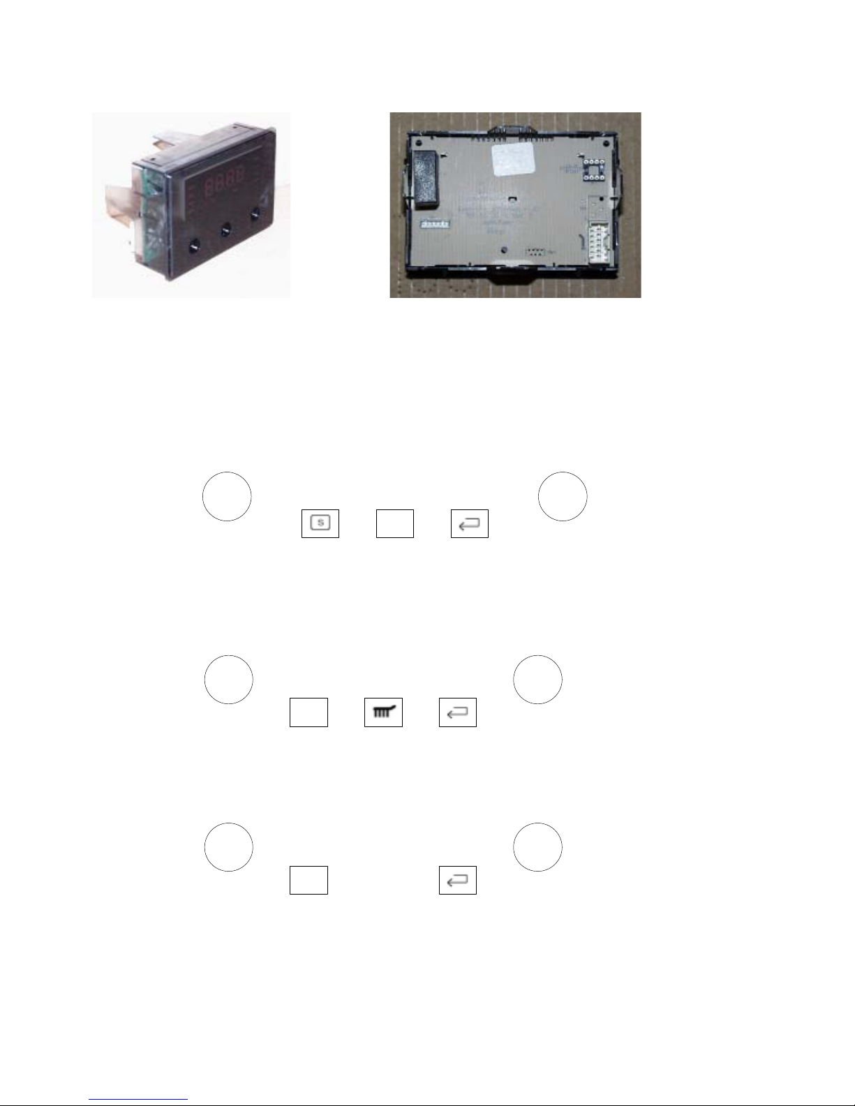
2.1 Illustration of the input electronics (UI) RHEA
2.2 Button / and display layouts of all appliance groups, countries and brand
- Button layout for all built-in appliance groups of the AEG brand (Germany, Export,
UK)
- Button layout for all appliance groups of the Arthur Martin Elux brand with Pyrolyse function or catalytic cleaning
- Button layout for all appliance groups of the Arthur Martin Elux brand without Pyrolyse
function

- 5 -
DGS-TDS-N 05.09 A. B. © Electrolux 599 518 252 EN
OVF/
PRG
+/-
Position rotary and
shuttle not analog
layout
Time/
Temp
KEY_MODE in
MP-fun ctiona lit
y
Time/
Temp
OVF/
PRG
+/-
OVF/
PRG
Position rotary and
shuttle not analog
layout
OVF/
PRG
Position rotary and
shuttle not analog
layout
+/-
Time/
Temp
IS-°C
OVF/
PRG
Position rotary and
shuttle not analog
layout
+/-
Time/
Temp
1 2 3 4
1 8 3 4 5
1 9 4 10
1 7 3 4 5
1 6 3 4 5
- Button layout for floor-mounted appliances of the Electrolux brand with meat
thermometer
- Button layout for built-in appliances of the AEG and Voss brands with meat thermometer
- Button layout for floor-mounted appliances M2-UK
- Button layout for built-in appliances of the Electrolux and Juno brands with Pyrolyse function
- Button layout for built-in appliances of the Electrolux brand without Pyrolyse function

- 6 -
DGS-TDS-N 05.09 A. B. © Electrolux 599 518 252 EN
2.3 Main features of operation
2.3.1 Clock setting following network reset
Information: The oven only functions with set time!
When the appliance must be connected again with the mains e.g. after a repair, you have to set the
clock anew. Proceed as follows:
a) Following connection or a power loss and depending on the display class, either the symbol
for the time of day blinks or the arrow in front of the the ‘time of day’ symbol blinks.
b) With the +/- buttons, it can also be a separate component when necessary (input module) to
set the time of day.
c) If need be, confirm with the MODE button (=Timer button) The appliance is ready for
operation.
2.3.2 Electronic child-safe function
Basic prerequisites: - Power supply voltage is connected
- No oven function selected.
- If the appliance is equipped with a Main Switch, then this
must be activated
To activate and deactivate the child-safety function, the MODE button (=Timer button)
must be activated together with the „„Minus“ button, or, with appliances featuring a
Temperature Selection Switch, this must be put into the „Minus“ position when activating
the MODE button (=Timer button).
1 - Separate component: Input module (Description Chapter 4)
Button 2 - Selection button - Quick Heating
Button 3 - Conversion button - Display Time / Temperature
Button 4 - Selection button MODE (e.g., clock, meat thermometer, etc.)
5 - Separate component: Input module (Description Chapter 4)
Button 6 - Selection button - Real temperature display
Button 7 - Selection button - Cleaning function
Button 8 - Selection button - Meat thermometer
Button 9 and 10 - Selection button - Parameter change Time / Temperature
- 7 -
DGS-TDS-N 05.09 A. B. © Electrolux 599 518 252 EN
3. Functions of appliance
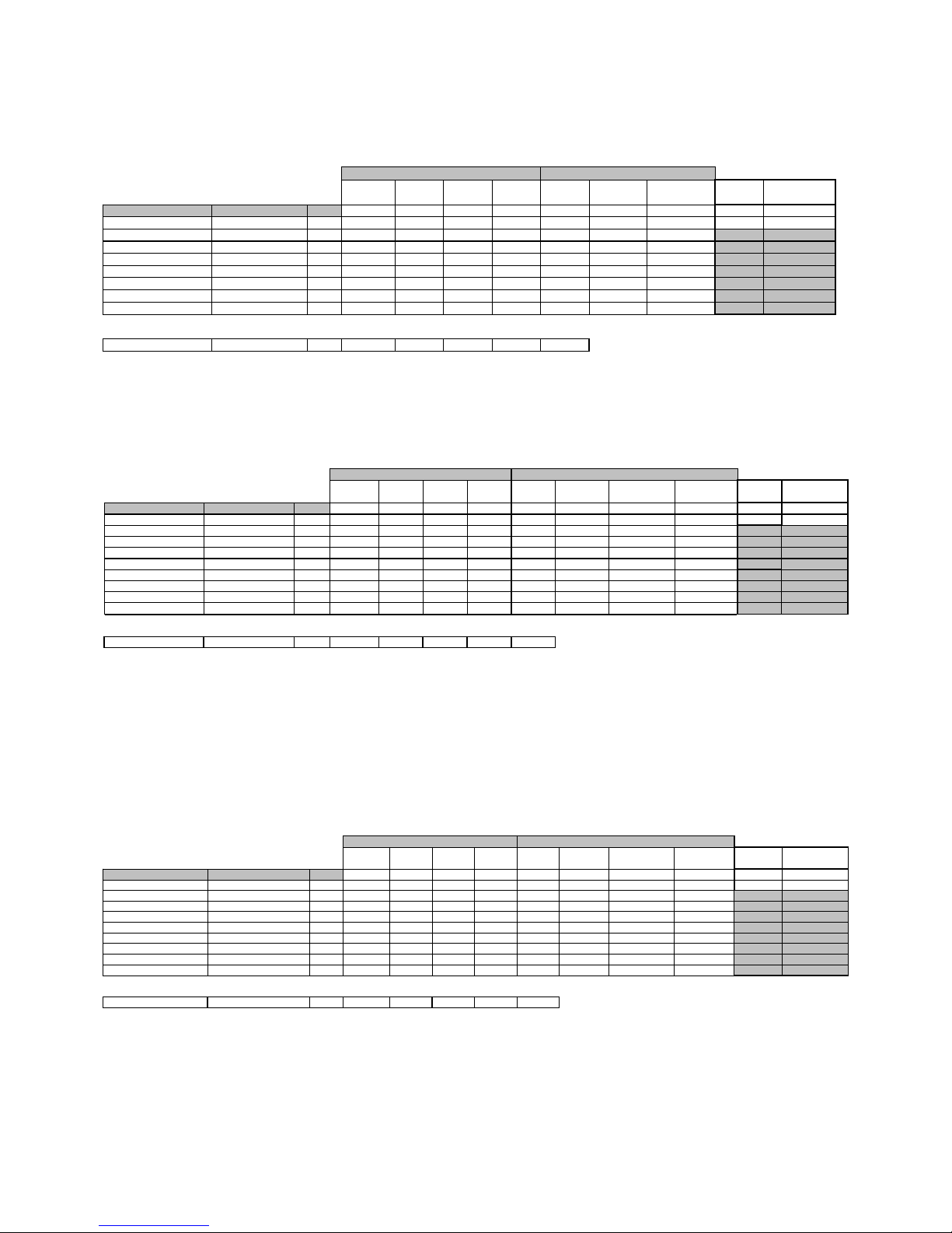
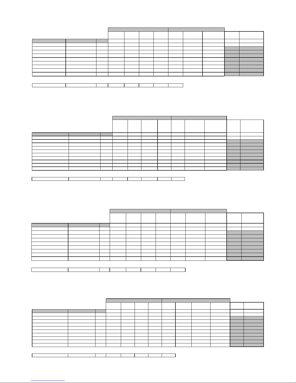
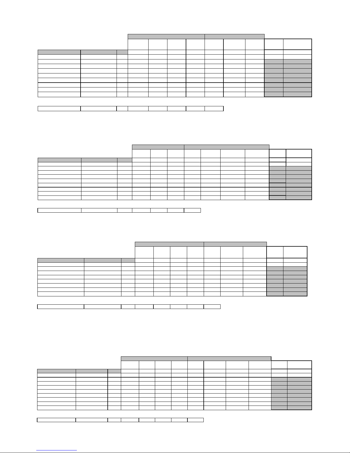
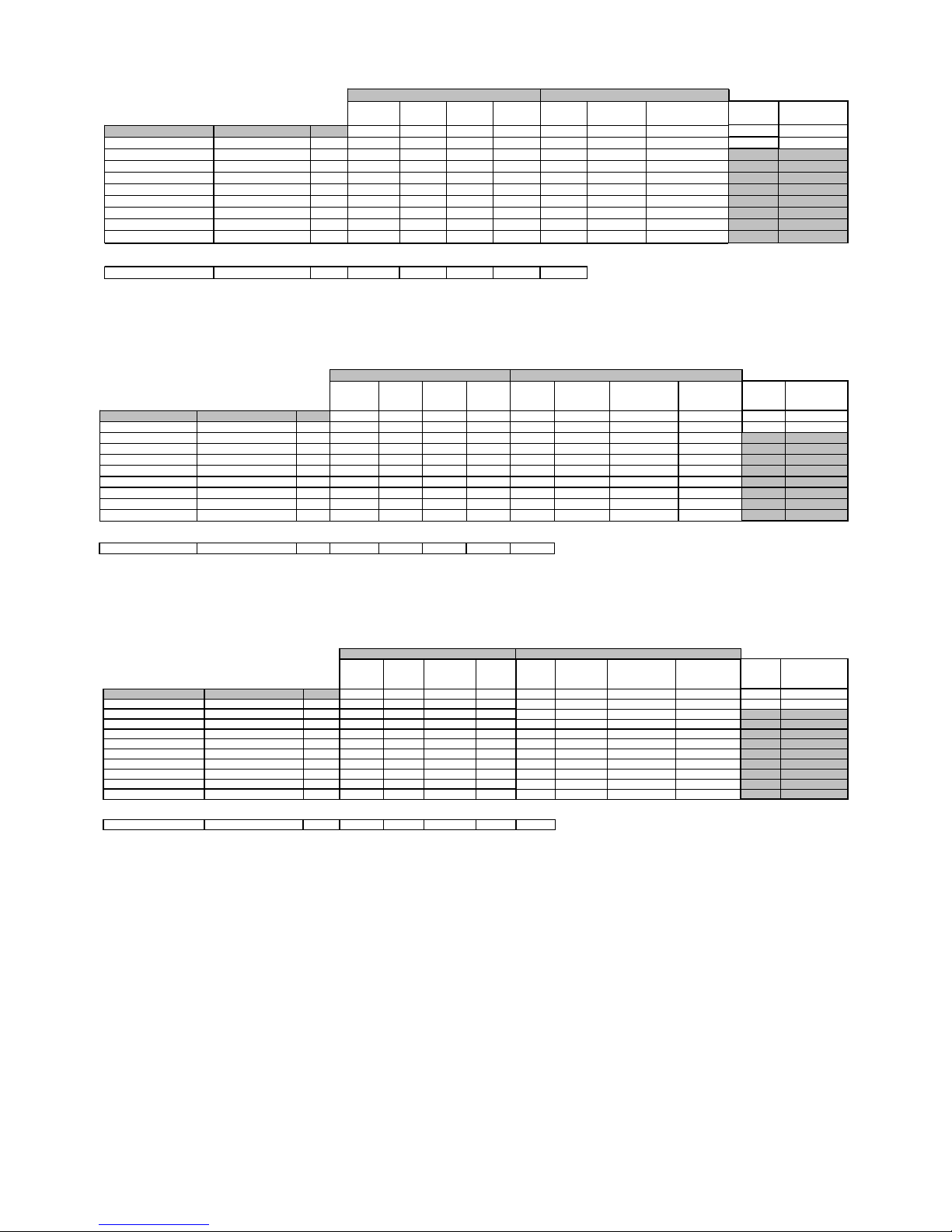
3.1 Oven functions, capacities and small consumer - appliance-specific
Brand / Mar k e t :
AE G (Nexxxt) Germany
Oven class
Perfect1-w ithout pyrolytical cleaning
Ele ct r o n ic:
OVC 1000
grill element
top
element
bottom
element
rear
element
cooking
fan cooling fan
oven lamp back
wall Powe r ( W)
current ampe re
(W)
oven functions suggested temperature Boos t 1900 1000 1000 1900 40 25 40
Pos.0 (OFF)
Pos . 1 (l i ght i ng) - - - - - - - X 40 0, 2
Pos.2 150 A - X X X X X X 3005 13,1
Pos .3 (t op -/bottom el .) 200 A - X X - - X X 206 5 9, 0
Pos.4 180 A X X - - X X X 3005 13,1
Pos.5 300 X X - - - X X 2965 12,9
Pos.6 30 - - - - X - X 80 0,3
Pos.7 150 - - X - - X X 1065 4,6
Manual booster A X X X
small loads (Watt)heatin g ele m ent s (W at t)
Brand / Market: AEG (Nexx xt) Germany
Oven class Perfect1-w ith pyrolytical cleaning
Electronic: OVC 1000
grill element
top
element
bottom
element
rear
element
cookin
g
fan cooling fan
oven lamp back
wall Türverriegelung Power (W)
oven function suggested temperat ure Boost 1900 1000 1000 1900 40 25 40 5
Pos.0 (OFF)
Pos. 1 (l i ght i ng) - - - - - - - X - 40
Pos.2 150 A- XXXX X X - 3005
Pos.3 (top-/bottom el.) 200 A - X X - - X X - 2065
Pos.4 180 A X X - - X X X - 3005
Pos.5 300 X X - - - X X - 2965
Pos.6 30 - ---XX - - 80
Pos.7 150 - - X - - X X - 1065
Pos. 8 (P yro2)
2 diff. D urations
X X X - X X - X 2930
Manual boost er A X X X
small loads (Watt)heating elements (W at t)
Brand / Market:
AEG (Nexxxt) UK
Oven clas s
P e rfect1-with pyro lytical cleaning
Electronic:
OVC 1000
grill element
top
element
bottom
element
rear
element
cooking
fan cooling fan
oven lamp back
wall Türverriegelung
oven functi on suggest ed t emperature Boost 1900 1000 1000 1900 40 25 40 5
Pos.0 (OFF)
Pos.1 300 X X - - - X X Pos.2 300 X - - - - X X Pos.3 150 A - X X X X X X -
Pos. 4 (top-/bottom el.) 200 A - X X - - X X -
Pos.5 180 A X X - - X X X Pos.6 150 A - X X - X X X Pos.7 30 - - - - X - X -
Pos. 8 (P yro2)
2 diff. Durations
XXX-XX - X
Manual boost er A X X X
small l oads (Wat t )heating element s (Watt)
current ampere
(W)
0,2
13,1
9,0
13,1
12,9
0,3
4,6
12,7
Power (W)
current ampere
(W)
2965 12,9
1965 8,5
3005 13,1
2065 9,0
3005 13,1
2105 9,2
80 0,3
2930 12,7
- 8 -
DGS-TDS-N 05.09 A. B. © Electrolux 599 518 252 EN
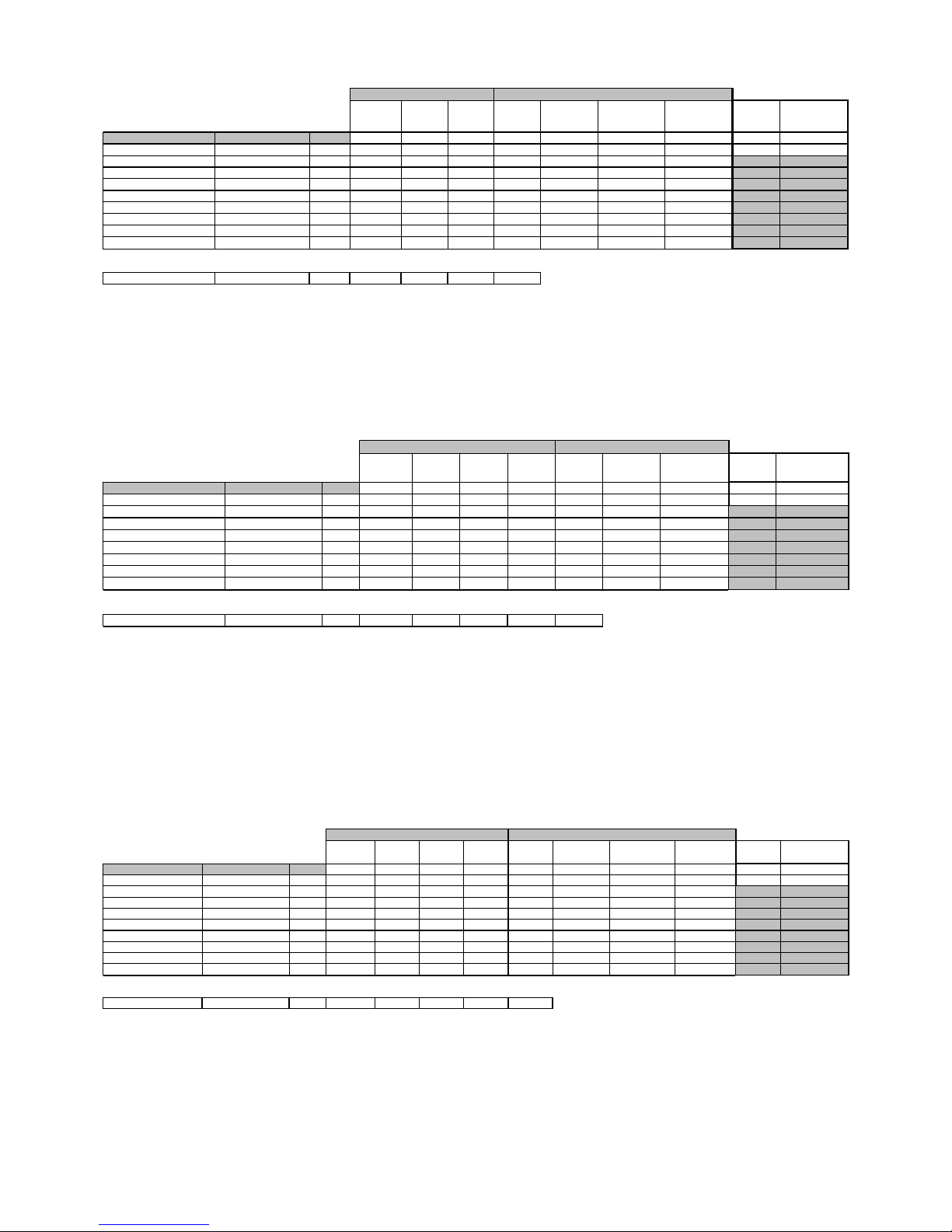
Brand / Market:
AEG (Nexxxt) Export
Oven class
Classic-with pyrolytical cleaning
Electronic:
OVC 1000
grill e l e ment
top
element
bottom
element
cooking
fan c ool i ng fan
oven lamp back
wall Türverriegelung
oven function suggested temperat u re Boos t 1900 1000 1000 40 25 40 5
Pos.0 (OFF)
Pos.1 (lighting) - - - - - - X -
Pos.2 150 A- XXX X X -
Pos .3 (top-/bottom el .) 200 A - X X - X X -
Pos.4 180 A X X - X X X Pos.5 300 X X - - X X Pos.6 30 - - - X - X Pos.7 150 - - X - X X -
Pos.8 (Pyro2) 2 diff . Dur ations X XXX X - X
Manual boos ter A X X X
smal l lo ads ( W a t t)heati ng el em ent s (Watt)
Power (W)
current ampere
(W)
40 0,2
2105 9,2
2065 9,0
3005 13,1
2965 12,9
80 0,3
1065 4,6
2930 12,7
Brand / Market: AEG (Nexxxt) Export
Oven class Perfect1-w ithout pyrolytical cleaning
Electronic: OVC 1000
grill element
top
element
bottom
element
rear
element
cooking
fan cool i ng fan
oven lamp back
wall
oven functi on s ugges ted tem perat ure Boost 1900 1000 1000 1900 40 25 40
Pos.0 (OFF)
Pos.1 150 A- XXXX X X
Pos.2 (top-/bottom el .) 200 A - X X - - X X
Pos.3 180 A X X - - X X X
Pos.4 300 X X - - - X X
Pos.5 300 X---- X X
Pos.6 30 - ---X - X
Pos.7 150 - - X - - X X
Manual booster A X X X
small loads (Watt)heating elements (Watt )
Power (W)
current ampere
(W)
3005 13,1
2065 9,0
3005 13,1
2965 12,9
1965 8,5
80 0,3
1065 4,6
Brand / Market: AEG (Nexxxt) Expor t
Oven class Perfect1-w ith pyrolytical cleaning
Electronic: OVC 1000
grill element
top
element
bottom
element
rear
element
cookin
g
fan cooling fan
oven lamp back
wall Türverriegelung
oven function su
gg
este d t em peratureBoost 1900 1000 1000 1900 40 25 40 5
Pos.0 (OFF)
Pos.1 150 A- XXXX X X -
Pos. 2 (top-/bot tom el. ) 200 A - X X - - X X -
Pos.3 180 A X X - - X X X Pos.4 300 X X - - - X X Pos.5 300 X - - - - X X Pos.6 30 - - - - X - X Pos.7 150 - - X - - X X -
Pos.8 (Pyro2)
2 diff. Duration s
XXX-X X - X
Manual boos t er A X X X
small l oads (Watt)heating elements (Watt )
Power (W )
current am p ere
(W)
3005 13,1
2065 9,0
3005 13,1
2965 12,9
1965 8,5
80 0,3
1065 4,6
2930 12,7

- 9 -
DGS-TDS-N 05.09 A. B. © Electrolux 599 518 252 EN
Brand / Market:
Arthur Martin
Oven class
without hot air system
Ele c t ro n ic:
OVC 1000
top/grill
element
bottom
element cool i ng fan
oven lamp back
wall
Motor
Gril s p i e ß P ow er (W)
current a m pe re
(W)
oven funct i on s ugges ted tem perature Boos t 2300 1000 25 4 0 40
Pos.0 (OFF)
Pos.1 200 X X X X - 3365 14,6
Pos.2 180 X X X X - 3365 14,6
Pos.3 250 X - X X - 2365 10,3
Pos.4 250 X - X X X 2405 10,5
Pos.5 210 A X X X X - 3365 14,6
Pos.6 80 X X X X - 3365 14,6
Pos.7 200 A X X X X - 3365 14,6
boost er "AUTO" A X
smal l l oads (Wat t )heating el em ent s (W at t )
Brand / Market:
Arthur Martin
Oven class
Circulated-(with hot air, without pyrolytical cleaning)
Electronic:
OVC1000
top/grill
element
bottom
element
cooking
fan cooling fan
oven lamp back
wall
Motor
Grillspieß Power (W)
current ampere
(W)
oven functi on sugges t ed t em perat ure Boost 2300 1000 40 25 40 40
Pos.0 (OFF)
Pos.1 180 X X - X X - 2365 10,3
Pos.2 180 X X X X X - 3405 14,8
Pos.3 200 X - X X X - 2405 10,5
Pos.4 250 X - - X X X 2405 10,5
Pos.5 210 A X X - X X - 3365 14,6
Pos.6 (keep warm ) 80 X X - X X - 3365 14,6
Pos.7 200 A X X - X X - 3365 14,6
booste r "AUTO" A X X
heating el em ents (Watt) small l oads (W att)
Brand / Market:
Arthur Martin
Oven class
Circulated-(w ith hot air and w ith pyrolytical cleaning)
Electronic:
OVC 1000
top/grill
element
bottom
element
cooking
fan cooli ng fan
oven lamp back
wall
Motor
Grillspieß Türverriegelung
oven functi on sugge s t ed t em perat ure Boos t 2300 1000 40 25 40 40 5
Pos.0 (OFF)
Pos.1 180 X X - X X - Pos.2 180 X X X X X - Pos.3 200 X-XX X- Pos.4 250 X - - X X X Pos.5 210 A X X - X X - -
Pos.6 (keep warm) 80 X X - X X - -
Pos.7 200 A X X - X X - -
Pos.8 (Pyro3)
3 diff. D urations
XXXX - - X
booster "AUTO" A X X
smal l l oads (W a t t )heating elements (Watt )
Power (W)
current ampere
(W)
2365 10,3
3405 14,8
2405 10,5
2405 10,5
3365 14,6
3365 14,6
3365 14,6
3330 14,5
Bran d / M ark e t:
Arthur Martin (ICON)
Oven class
Circulated-(w ith hot air and without pyrolytical cleaning)
Elect r on ic:
OVC 1000
top/grill
element
bottom
element
cooking
fan cooling fan
oven lamp back
wall
Motor
Grillspieß Power (W)
current a m pere
(W)
oven function s ugges t ed t emperature Boost 2300 1000 40 25 40 40
Pos. 0 (OFF)
Pos .1 (t op-/bot tom el .) 180 X X - X X - 3365 14,6
Pos.2 180 X X X X X - 3405 14,8
Pos.3 200 X - X X X - 2365 10,3
Pos.4 250 X - - X X X 2405 10,5
Pos.5 210 A X X - X X - 3365 14,6
Pos .6 (kee p warm) 80 X X - X X - 3365 14,6
Pos.7 200 A X X - X X - 3365 14,6
Pos.8 250 X X X X X - 3405 14,8
booster " AUTO" A X X
small l oads (W at t )heating elements (W at t )
- 10 -
DGS-TDS-N 05.09 A. B. © Electrolux 599 518 252 EN
Brand / Market: AEG UK
Oven class Ovens (M2)
Ele ct r on i c: OVC 1000
grill element
top
element
bottom
element
rear
element
cooking
fan c o olin g fa n
oven lamp back
wall
oven function s ugges ted temperature Boost 1900 1000 1000 1900 40 25 40
Pos.0 (OFF)
Pos.1 (lighting) - - - - - - - X
Pos.2 300 X - - - - X X
Pos.3 150 A- XXXX X X
Pos.4 (t op-/ bot t om el .) 200 A - X X - - X X
Pos.5 180 X - - - X X X
Pos.6 150 A - X X - X X X
Pos.7 30 - - - - X - X
Pos.8 120/80 - XXXX X X
booster "A UTO" A X X X
small loads (Watt)heating element s (Watt)
Power (W)
current a m pere
(W)
40 0,2
1965 8,5
3005 13,1
2065 9,0
2005 8,7
2105 9,2
80 0,3
3005 13,1
Brand / Market:
El ectrolux / Juno
Oven clas s
with pyrolytical cleaning
Ele ct r o n i c :
OVC 1000
grill element
top
element
bottom
element
rear
element
cooking
fan cooling fan
oven lamp back
wall
oven function s uggested temperature Boost 1900 1000 1000 2400 40 25 40
Pos.0 (OFF)
Pos.1 (lighting) - - - - - - - X
Pos.2 180 - - - X X X X
Pos. 3 (top-/ bottom el.) 200 A - X X - - X X
Pos.4 200 A - - X X X X X
Pos.5 180 A X - - - X X X
Pos.6 250 X - - - - X X
Pos.7 250 X X - - - X X
Pos.8 120 - - X - - X X
Pos.9 (P y ro2)
2 diff. Dur atio ns
XX X -X X -
booster "A UTO" A X X X
small l oads (W at t )heating elements (Watt)
Power (W) c urrent ampere (W )
40 0,2
2505 10,9
2105 9,2
3505 15,2
2005 8,7
1965 8,5
2965 12,9
1065 4,6
2970 12,9
Brand / Market: AEG (Century1)
Oven class without pyrolytical cleaning
Electronic: OVC 1000
grill element
top
element
bottom
element
rear
element
cooking
fan c ool i ng fan
oven lamp bac k
wall
oven functi on suggest ed temperature Boost 1900 1000 1000 1900 40 25 40
Pos.0 (OFF)
Pos.1 (lighti ng) - - - - - - - X
Pos.2 150 A - X X X X X X
Pos.3 (top-/bot tom el. ) 200 A - X X - - X X
Pos.4 180 A X X - - X X X
Pos.5 300 X X - - - X X
Pos.6 300 X - - - - X X
Pos.7 30 - ---X - X
Pos.8 150 - - X - - X X
Manual booster A X X X
small l oads (Wat t)heating element s (Watt)
Power (W)
current ampere
(W)
40 0,2
3005 13,1
2065 9,0
3005 13,1
2965 12,9
1965 8,5
80 0,3
1065 4,6
Bra nd / Mar k et:
AEG (Century1)
Oven class
with pyrolytical cleaning
Ele ct r o n i c:
OVC 1000
grill element
top
element
bottom
element
rear
element
cookin
g
fan cooling fan
oven lamp bac k
wall Türv erriegelung
oven function suggested temperature Boost 1900 1000 1000 1900 40 25 40 5
Pos.0 (OFF)
Pos.1 (lighting) - - ---- - X -
Pos.2 150 A- XXXX X X -
Pos.3 (top-/bottom el.) 200 A - X X - - X X -
Pos.4 180 A X X - - X X X Pos.5 300 XX--- X X Pos.6 300 X---- X X Pos.7 30 - ---X - X Pos.8 150 --X--X X -
Pos.9 (Pyro2)
2 diff. Dur ations XXX-XX - X
Manual booster A X X X
small l oads (W at t )heating elem en ts (Watt)
Power (W)
current ampere
(W)
40 0,2
3005 13,1
2065 9,0
3005 13,1
2965 12,9
1965 8,5
80 0,3
1065 4,6
2930 12,7
- 11 -
DGS-TDS-N 05.09 A. B. © Electrolux 599 518 252 EN
Brand / M ar k e t :
AEG (Nexxxt) UK - double oven
Oven clas s
without pyrolytical cleaning
Electronic:
OVC 1000
grill elem ent
top
element
bottom
element
rear
element
cooking
fan cooling fan
oven lamp
back wall Power (W)
current am pere
(W)
oven functi on
s
uggested t em perat ureBoost 1600 700 1000 2000 13 25 25
Pos.0 (OFF)
Pos . 1 (l ighting) - - - - - - X 25 0,1
Pos.2 250 X X - - - X X 2350 10,2
Pos.3 250 X - - - - X X 1650 7,2
Pos.4 150 A - X X X X X X 3063 13,3
Pos. 5 (top-/bottom el. ) 200 A - X X - - X X 1750 7,6
Pos.6 180 A X X - - X X X 2363 10,3
Pos.7 150 A - X X - X X X 1763 7,7
Pos.8 30 - - - - X - X 38 0,2
Manual booster A X X X
heating elem ent s (Watt) small loads (W at t)
Brand / Market:
AEG Export
Oven clas s
Classic
Ele ct r on i c:
OVC 2000
grill element
top
element
bottom
element
cooking
fan coo l ing fa n
oven lamp back
wall door loc k Power (W)
oven functions suggested temperature Boost 1900 1000 1000 40 25 40 5
Pos.0 (OFF)
Pos. 1 (li ght ing) - - - - - - X - 40
Pos.2 150 A - X X X X X - 2105
Pos.3 (top-/ bo ttom el.) 200 A - X X - X X - 2065
Pos.4 180 A X X - X X X - 3005
Pos.5 300 X X - - X X - 1965
Pos.6 30 - - - X - X - 80
Pos.7 150 --X-X X -1065
Pos.8 (Pyro2)
2 diff. Durati ons
XXXX X - X2930
Manual booster A X X X
small l oads (W att)heating elements (W att)
current am pe re
(W)
0,2
9,2
9,0
13,1
8,5
0,3
4,6
12,7
Brand / Market:
AEG Export
Oven class
Perfect1w ithout pyrolytical cleaning
Ele ct r oni c :
OVC 2000
grill element
top
element
bottom
element
rear
element
cooking
fan cooli ng fan
oven lamp back
wall
oven functions suggested t emperat ure Boost 1900 1000 1000 1900 40 25 40
Pos.0 (OFF)
Pos.1 150 A- XXXX X X
Pos. 2 (top-/bot t om el. ) 200 A - X X - - X X
Pos.3 180 A X X - - X X X
Pos.4 300 XX--- X X
Pos.5 300 X---- X X
Pos.6 30 - - - - X - X
Pos.7 150 - - X - - X X
Manual booster A X X X
sm all lo ads (Watt)heating element s (Watt)
Power (W)
current ampere
(W)
40 0,2
2105 9,2
2065 9,0
3005 13,1
1965 8,5
80 0,3
1065 4,6
Brand / M arket: AEG Export
Oven clas s Perfect1 w ith pyrolytical cleaning
Ele ct r on i c : OVC2000
grill element
top
element
bottom
element
rear
element
cookin
g
fan cooling fan
oven lamp back
wall door lock
oven functi ons su
gg
ested temperature Boos t 1900 1000 1000 1900 40 25 40 5
Pos.0 (OFF)
Pos.1 150 A- XXXX X X X
Pos. 2 (t op-/bot tom el.) 200 A - X X - - X X -
Pos.3 180 A X X - - X X X Pos.4 300 X X - - - X X Pos.5 300 X---- X X Pos.6 30 - ---X - X Pos.7 150 - - X - - X X -
Pos.8 (Pyro2)
2 diff. Durations
XXX-X X - X
Manual booster A X X X
small loads (Watt)heating elements (Watt)
Power (W)
current ampere
(W)
40 0,2
2105 9,2
2065 9,0
3005 13,1
1965 8,5
80 0,3
1065 4,6
2930 12,7
- 12 -
DGS-TDS-N 05.09 A. B. © Electrolux 599 518 252 EN
Bran d / M ark e t :
ELECTROLUX
Oven class
Ovens (M2) without pyrolytical cleaning
Ele ctr o n i c :
OVC 2000
grill element
top
element
bottom
element
rear
element
cooking
fan cooli ng fan
oven lamp back
wall Po we r (W)
oven function s sugges ted te m pe rature Boos t 1900 1000 1000 1900 40 25 40
Pos.0 (OFF)
Pos.1 180 - - - X X X X 2105
Pos.2 (top-/bottom el.) 200 A - X X - - X X 2065
Pos.3 190 - - X X X X X 3005
Pos.4 120/80 - - - X X X X 2105
Pos.5 200 X X - - X X X 3005
Pos.6 250 X X - - - X X 2965
Pos.7 30 - -X-X - X 1080
Pos . 8 (Beleucht ung)
- ----- - X 40
Manual booster"AUTO" A X X X
small load s ( Watt)heating elements (W at t )
current ampere
(W)
9,2
9,0
13,1
9,2
13,1
12,9
4,7
0,2
Brand / Market: ELECTROLUX
Oven clas s Ovens (M2) with pyrolytical cleaning
Electronic: OVC 2000
grill element
top
element
bottom
element
rear
element
cooking
fan c o o ling fa n
oven lamp back
wall door lock
oven functions suggested temperature Boost 1900 1000 1000 1900 40 25 40 5
Pos.0 (OFF)
Pos.1 180 - - - X X X X -
Pos.2 (top-/bott om el .) 200 A - X X - - X X -
Pos.3 190 - - X X X X X Pos.4 120/80 - - - X X X X Pos.5 200 X X - - X X X Pos.6 250 X X - - - X X Pos.7 30 - -X-X - X -
Pos.8 (Pyro2)
2 diff. Dur atio ns XXX-X X - X
Manual booster"AUTO" A X X X
small loads (Watt)heating elements (Watt)
Power (W)
current am pere
(W)
2105 9,2
2065 9,0
3005 13,1
2105 9,2
3005 13,1
2965 12,9
1080 4,7
2930 12,7
Brand / M ar k e t:
Electrolux / Juno
Oven clas s
with pyrolytical cleaning
Ele ct r o n ic :
OVC 1000
grill element
top
element
bottom
element
rear
element
oven functions s uggested temperature Boost 1900 1000 1000 2400
Pos.0 (OFF)
Pos.1 (lighting) - - - - -
Pos.2 180 - - - X
Pos.3 (top-/bottom el . ) 200 A - X X -
Pos.4 200 A - - X X
Pos.5 180 A X - - Pos.6 250 X - - Pos.7 250 X X - Pos.8 120 - - X -
Pos.9 (Py ro)
2 diff. D urations
XX X -
Manual booster"AUTO" A X X
heating el e m ent s (Watt)
cooking
fan cooli n g fan
oven lamp back
wall door lock Power (W)
current am pe re
(W)
40 25 40 5
-- X - 400,2
X X X - 2505 10,9
- X X - 2065 9,0
X X X - 3505 15,2
X X X - 2005 8,7
- X X - 1965 8,5
- X X - 2965 12,9
- X X - 1065 4,6
X X - X 2930 12,7
X
small loads (Watt)
- 13 -
DGS-TDS-N 05.09 A. B. © Electrolux 599 518 252 EN
100
200
300
400
500
min
° C
P1P2P3
90 120
150
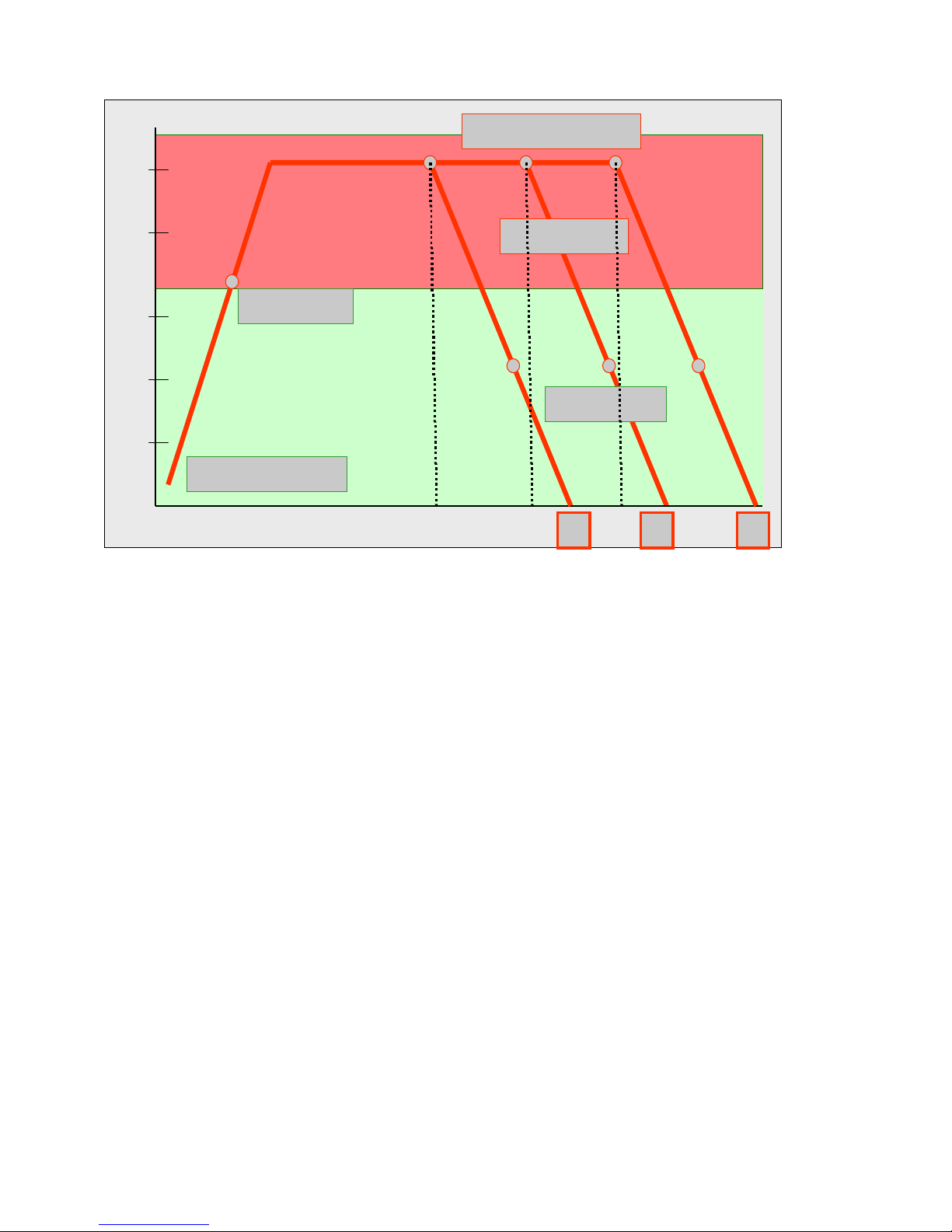
Fig. heating-up curve temperature (°C) / time (min
With the Pyroluxe self-cleaning system the residues in the interior are carbonized to ashes at high
temperatures. The centre of gravity temperature of the muffle is approx. 500°C.
A max. selection of three pyrolysis durations (P…) can be made per appliance class and
equipment.
Pyrolysis duration (heating duration)
P1 > Heating period 150min
P2 > Heating period 120min
P3 > Heating period 90min
Note: In appliances which are equipped with two pyrolysis durations, P2 corresponds to the
pyrolysis duration P3.
3.2 Pyrolitical cleaning - Explanation
end of heating phase
cooling phase
door locked
door unlocked
room temperature
 Loading...