


Built-in Side by Side Refrigerator
May 2005
1
5995432258

SAFE SERVICING PRACTICES - ALL APPLIANCES
To avoid personal injury and/or property damage, it is important that Safe
Servicing Practices be observed. The following are some limited examples of safe
practices:
1. DO NOT attempt a product repair if you have any doubts as to your ability to
complete it in a safe and satisfactory manner.
2. Before servicing or moving an appliance:
• Remove the power cord from the electrical outlet, trip the circuit breaker to
the OFF position, or remove the fuse.
• Turn off the gas supply.
• Turn off the water supply.
3. Never interfere with the proper operation of any safety device.
4. USE ONLY REPLACEMENT PARTS CATALOGED FOR THIS APPLIANCE.
SUBSTITUTIONS MAY DEFEAT COMPLIANCE WITH SAFETY
STANDARDS SET FOR HOME APPLIANCES.
5. GROUNDING: The standard color coding for safety ground wires is GREEN,
or GREEN with YELLOW STRIPES. Ground leads are not to be used as current
carrying conductors. It is EXTREMELY important that the service technician
reestablish all safety grounds prior to completion of service. Failure to do so
will create a hazard.
6. Prior to returning the product to service, ensure that:
• All electrical connections are correct and secure
• All electrical leads are properly dressed and secured away from sharp
edges, high-temperature components, and moving parts
• All non-insulated electrical terminals, connectors, heaters, etc. are
adequately spaced away from all metal parts and panels
• All safety grounds (both internal and external) are correctly and securely
connected
• All panels are properly and securely reassembled
ATTENTION!!!
This service manual is intended for use by persons having electrical and mechnical
training and a level of knowledge of these subjects generally considered acceptable in the
appliance repair trade. Electrolux Home Products cannot be responsible, nor assume any
liability, for injury or damage of any kind arising from the use of this manual.
© 2001 White Consolidated Industries
25995432258

Table of Contents
3-Way Valve .................................................................................................................................40
Auger Motor .................................................................................................................................32
Casters and Leveling ....................................................................................................................26
Components ................................................................................................................................. 23
Component Locator Views ...........................................................................................................12
Component Resistance Values ...................................................................................................... 8
Compressor .................................................................................................................................. 39 - 61to 65
Control Features ............................................................................................................................10
Cube Motor and Cube Reed Switch ..............................................................................................32
Defrost Cycles ...............................................................................................................................43
Diagnostic Mode ...........................................................................................................................54
Dispenser Control Panel ................................................................................................................34
Dispenser Heater ...........................................................................................................................37
Dispenser Switch ...........................................................................................................................37
Doors ............................................................................................................................................ 23
Door Closer Assembly ...................................................................................................................25
Door Switches ............................................................................................................................... 41
Door Water Line Replacement .......................................................................................................38
Drain Pan ...................................................................................................................................... 26
Drier .............................................................................................................................................. 40
Duct Door Assembly ......................................................................................................................36
Evacuation and Charging Procedure ............................................................................................. 16
Fans .............................................................................................................................................. 44
Freezer Evaporator Assembly ....................................................................................................... 46
Freezer Evaporator Components .................................................................................................. 49
Freezer Heater Testing .................................................................................................................. 46
Fresh Food Evaporator Assembly ................................................................................................. 50
Fresh Food Evaporator Components ............................................................................................ 52
Fresh Food Heater Testing ............................................................................................................ 50
Heat Exchanger ............................................................................................................................. 39
Icemaker Controls ..........................................................................................................................11
Icemaker Fill Tube and Heater .......................................................................................................31
Ice Bin and Icemaker .....................................................................................................................31
Ice Dispenser ................................................................................................................................ 35
Installation Example 42" Model ......................................................................................................5
Interior Airfl ow .............................................................................................................................17
Interior Lights ................................................................................................................................42
Introduction ................................................................................................................................... 4
Machine Compartment Access Door .............................................................................................23
Main Switch ..................................................................................................................................34
Mufflers .........................................................................................................................................39
Nomenclature ............................................................................................................................... 9
Power Control Board (PCB) ..........................................................................................................27
Refrigerant Flow ............................................................................................................................14
Refrigeration Components .............................................................................................................13
Refrigeration System .....................................................................................................................13
Replacing the Freezer or Fresh Food Evaporator ........................................................................ 52
Schematics ................................................................................................................................... 58
Service Diagnostics ...................................................................................................................... 54 to 65
Technical Data ............................................................................................................................... 8
Terminal Block Panel .....................................................................................................................29
Thermistors ................................................................................................................................... 42
Troubleshooting Notes .........................................................................................................
Water Valve and Water T ank ......................................................................................................... 35
......... 57
IntroductionINTRODUCTION
3
5995432258
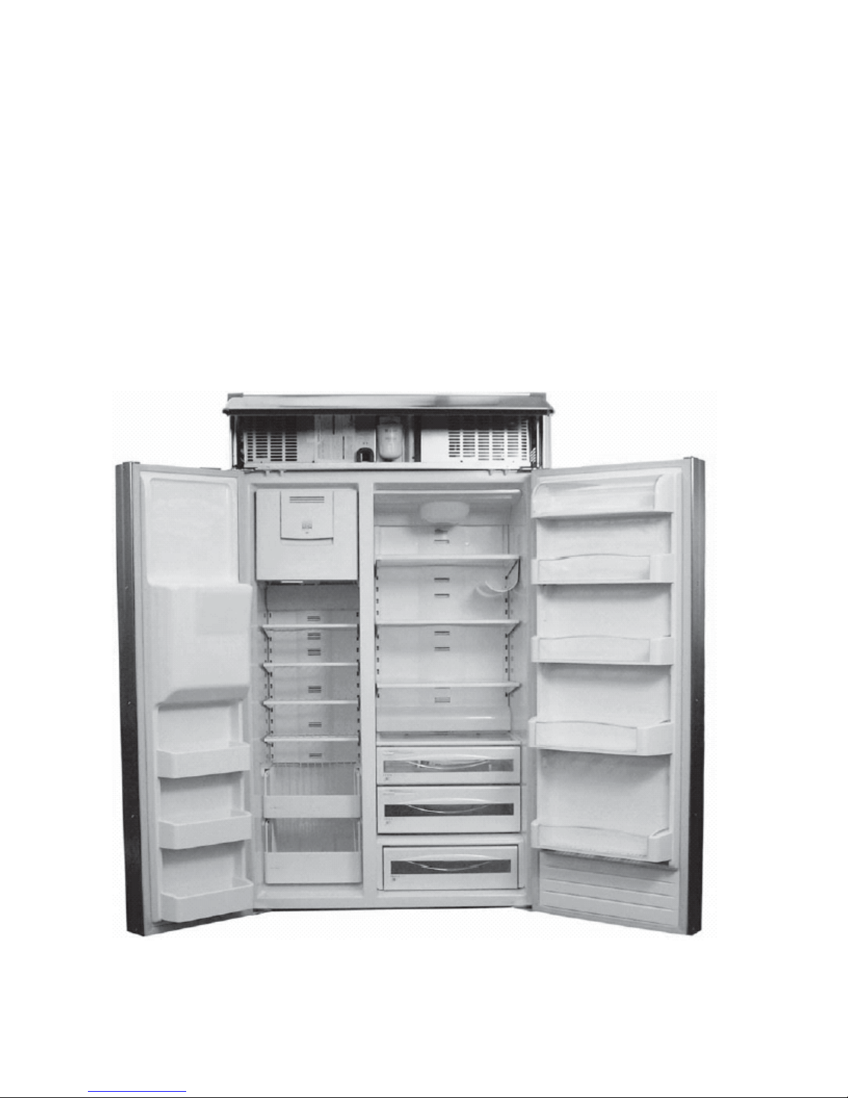
INTRODUCTION
The new Profi le Built-In Side by Side refrigerator has the following features:
•
•
•
•
•
•
•
•
•
Separate freezer and fresh food evaporators are recessed into the machine compartment for
increased effi ciency and interior space savings.
3-Way valve directs refrigerant fl ow where needed.
High-and low-side sealed system muffl ers quiet the operation.
Inverter is built into the power control board (PCB).
Combined dispenser and temperature control board provides customer control and test mode
operations.
Dispenser cube motor and cam replaces solenoid-operated cube mechanism.
Room ambient thermistor aids power control board (PCB) operation.
Component electrical testing is performed at the machine compartment-mounted terminal block.
Rear leveling mechanism is front-adjustable.
Installation Example 42" Mo
45995432258
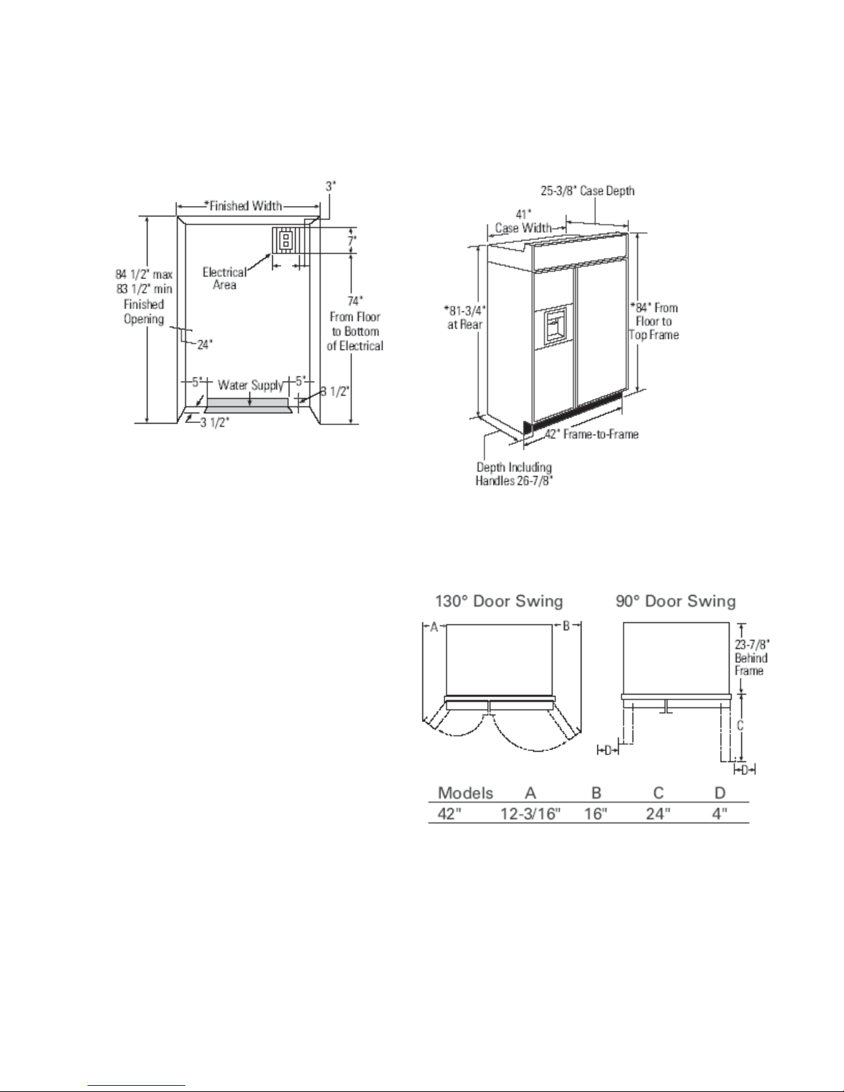
INSTALLATION EXAMPLE 42” MODEL
THE INSTALLATION SPACE
7”
* The finished cutout width must be:
41-1/2” for 42” models
Water and Electrical Locations
The opening must be prepared with the
electrical and water supply located as shown.
The cutout depth must be 24"
The refrigerator will project forward, slightly
beyond adjacent cabinets, depending on
your installation.
Additional Specifications
• A 120 volt, 60Hz, 15 or 20 amp power
supply is required. An individual properly
grounded branch circuit or circuit breaker
is recommended. Install a properly
grounded 3-prong electrical receptacle
recessed into the back wall. Electrical must
be located on rear wall as shown.
Note: GFI (ground fault interrupter) is not
recommended.
• Water line can enter the opening through
the floor or rear wall. The water line installed
should be 1/4" O.D. copper tubing between the
cold water line and water connection location.
The line should be long enough to extend to
the front of the refrigerator. Installation of an
easily accessible shutoff valve in the water line
is required.
Wood Panel 70 LB food door 30 LB freezer door
DIMENSIONS AND CLEARANCES
*Shipping height
The front height
may be adjusted
from 83-1/2" to 84-1/2"
by adjusting front and
rear leveling legs a
maximum of 1".
Product Clearances
These refrigerators are equipped with a 2
position door stop. The factory set 130° door
swing can be adjusted to 90° if clearance to
adjacent cabinets or walls is restricted
May Change with
our handle
Allow minimum clearances for Freezer
door (Dimension A) and Fresh Food door
(Dimension B) for a full 130° door swing
and to allow for drawer removal.
Four inch (4") minimum clearance is required
when door swing is adjusted to 90°. If the 90°
door stop position is used, drawer access is
maintained, but drawer removal is restricted.
5
5995432258
65995432258
DISCONNECT POWER CORD BEFORE SERVICING
IMPORTANT - RECONNECT ALL GROUNDING
DEVICES
7
5995432258

TECHNICAL DATA
All parts of this appliance capable of conducting
electrical current are grounded. If grounding
wires, screws, straps, clips, nuts or washers
used to complete a path to ground are removed
for service, they must be returned to their
original position and properly fastened.
CAUTION
To avoid personal injury when servicing the
condensing unit, stand on a ladder which will
give enough support to allow removal of the top
panel and safely allow access to service the unit.
REFRIGERA TION DIAGNOSIS
ELECTRICAL SPECIFICA TIONS
Max Defrost Control
w/No Door Openings........................16 hrs
Evap Defrost Thermistor........68°F (FZ)..63°F (FF)
Electrical Rating: 115V AC 60 HZ.............5.4 amp
Maximum Current Leakage......................0.75 mA
Maximum Ground Path Resistance...............0.1 W
Energy Consumption Model 42........50.5 KWh/mo
Energy Consumption Model 48......53.75 KWh/mo
COMPOENENT RESISTANCE VALUES
FF fan motor ……………………..............1600 &! ± 20%
FZ fan motor ………………………….......1600 &! ± 20%
Condenser fan motor ………………........1600 &! ± 20%
Auger motor ………………………..............3.7 &! ± 15%
Cube motor …………………………….....2091 &! ± 10%
Cover motor ……………………………....2091 &! ± 10%
Defrost heater FZ ……..................................44 &! ± 7%
Drain heater FZ ..........................................377 &! ± 7%
Sub-heater FZ ………...............................1322 &! ± 7%
Defrost heater FF .......................................120 &! ± 7%
Drain heater FF …......................................440 &! ± 7%
Fill-tube heater .……….............................2645 &! ± 7%
Dispenser heater (Recess)………………..1889 &! ± 7%
Compressor (between the different
phase) …………….....................11. 7 &! ± 7% / 1 phase
3- way valve …………………………..40 ± 4 &!/ 1 phase
Water valve (Ice maker) …………...............180 &! ± 7%
Water valve (Dispenser) ..………................325 &! ± 7%
IMPORTANT SAFETY NOTICE
This information is intended for use by individuals
possessing adequate backgrounds of electrical,
electronic and mechanical experience. Any
attempt to repair a major appliance may result
in personal injury and property damage. The
manufacturer or seller cannot be responsible for
the interpretation of this information, nor can it
assume any liability in connection with its use.
NO LOAD PERFORMANCE
Control Position 37-0°F and
Ambient T emperature of: 70°F 90°F
Fresh Food °F 37-42 36-43
Frozen Food °F (-2)-2 (-2)-5
Percent Running Time, %..........35-45 65-75
REFRIGERATION DIAGNOSIS
To access the low pressure side of the system,
install a line tap valve on the process tube
extending from the compressor case.
REFRIGERATION SYSTEM
Refrigerant Charge (R134a)......................8.11 ounces
Compressor......................................738-1270 BTU/hr
Minimum Compressor Capacity
Vacuum..........................................................26 inches
Minimum Equalized Pressure
@70°F.............................................................66 PSIG
@90°F.............................................................74 PSIG
To change the
Technical Data
Nomenclature
Icemaker Controls
85995432258
MODEL AND SERIAL NUMBER INFORMATION
E42BS85EPS THE PS IS FOR STAINLESS STEEL
E42BS75ETT THE TT IS FOR MODEL WITH TRIM ON DOORS
Serial Plate
Location
The Serial
plate is located
at the top of
the fresh food
section on the
right-side wall.
It contains
the model and
serial numbers
and specifi es
the minimum
installation clearances, electrical voltage,
frequency, maximum amperage rating, and
refrigerant charge.
Mini-Manual
The mini-manual is located behind the
grille panel at the top of the refrigerator.
When service is completed, return the
mini-manual to its original location for
future use.
Serial Number
The first letter tells us where the product was made, the
second letter tells us what type product it is. The first
number is the year the product was made. The next two
numbers are the week the product was made.
Example BA51400000,
B - Is the Anderson refrigerator factory.
A - Is a refrigerator
5 - Is 2005
14 - Is week 14
The rest of the numbers are the sequence number for week
14 of 2005.
9
5995432258
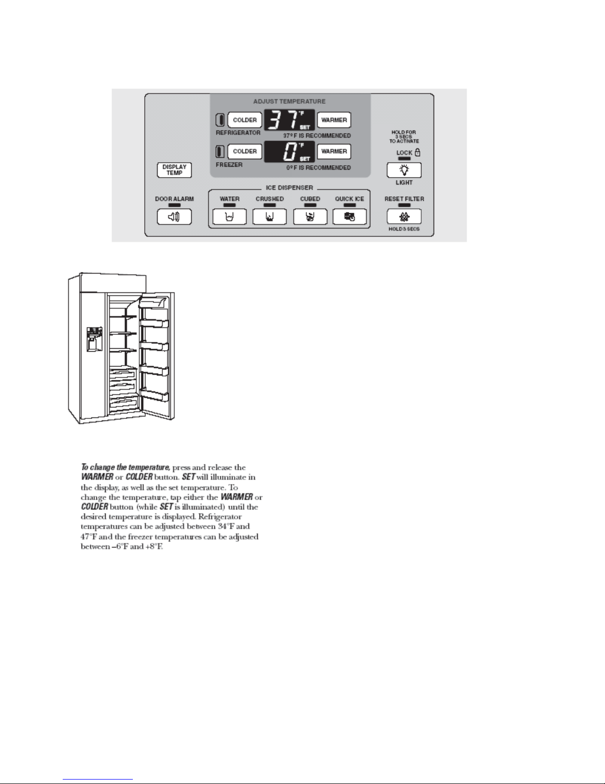
Control Features
The temperature controls are preset in the factory at 37°F for the
refrigerator compartment and 0°F for the freezer compartment. Allow
24 hours for the temperature to stabilize to the preset recommended
settings.
The temperature controls can display both the SET temperature
as well as the actual temperature in the refrigerator and freezer.
The actual temperature may vary slightly from the SET temperature
based on usage and operating environment.
NOTE: The refrigerator is shipped with protective film covering the
temperature controls. If this film was not removed during installation,
remove it now.
Icemaker Controls
Once the desired temperature has been set,
the temperature display will clear after 10 seconds.
To display the temperature, the DISPLAY TEMP
button may be tapped.
Several adjustments may be required. Each time
you
adjust controls, allow 24 hours for the refrigerator
to
reach the temperature you have set.
105995432258
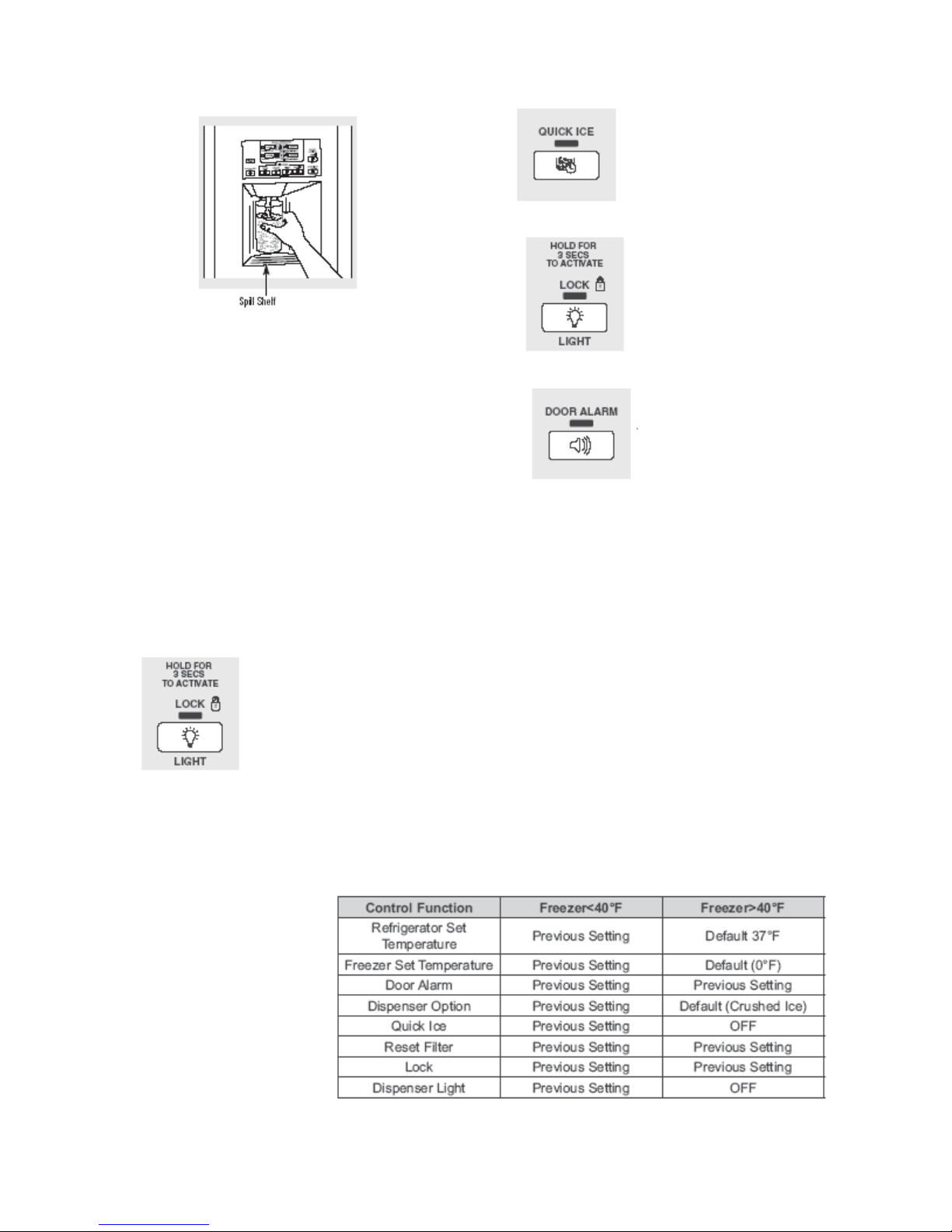
To Use the Dispenser
Select CUBED , CRUSHED or WATER . Press the glass
gently against the middle of the dispenser pad. The spill shelf
is not self-draining.To reduce water spotting, the shelf and
its grille should be cleaned regularly.
If no water is dispensed when the refrigerator is first
installed, there may be air in the water line system. Press
the dispenser arm for at least two minutes to
remove trapped air from the water line and to fill the water
system. To flush out impurities in the water line, throw
away the first six glassfuls of water.
CAUTION:
Never put fingers or any other objects into the ice crusher
discharge opening.
Locking the Dispenser
Press the LOCK/LIGHT
button for 3 seconds to lock the
dispenser and control panel. To
unlock, press and hold the button
again for 3 seconds.
Quick Ice
When you need ice in a hurry,
press this button to speed up ice
production. This will increase ice
production for the following
48 hours or until you press the
button again.
Dispenser Light
This button turns the night light
on the dispenser on and off.
The light also comes on when
the dispenser pad is pressed. If
this light burns out, it should be
replaced with a 6 watt 12V
maximum bulb.
Door Alarm
To turn the Door Alarm on, press
the DOOR ALARM button once.
The ACTIVE light will come on.
To turn it off, press it again.
When the DOOR ALARM is
active, the ACTIVE light will
flash if you open the door and
beep if you keep the door open
for more than 2 minutes. The
light goes out and the beeping
stops when you close the door.
Spill Shelf
Note: When QUICK ICE is selected, the freezer
temperature operates at -9°F for 48 hours or until QUICK
is pressed again. There is no change of temperature on
ICE
the display panel. In the event of a power loss, if the
freezer temperature is above 40°F, Quick Ice will not
restart. Below 40°F, the refrigerator will return to
the Quick Ice mode.
Display after power failure:
After a power failure, the
display will reset based
on freezer temperature.
If the freezer temperature
is below 40°F, the display
will retain the settings
prior to power loss. The
chart at the right describes
the possible settings.
11
5995432258
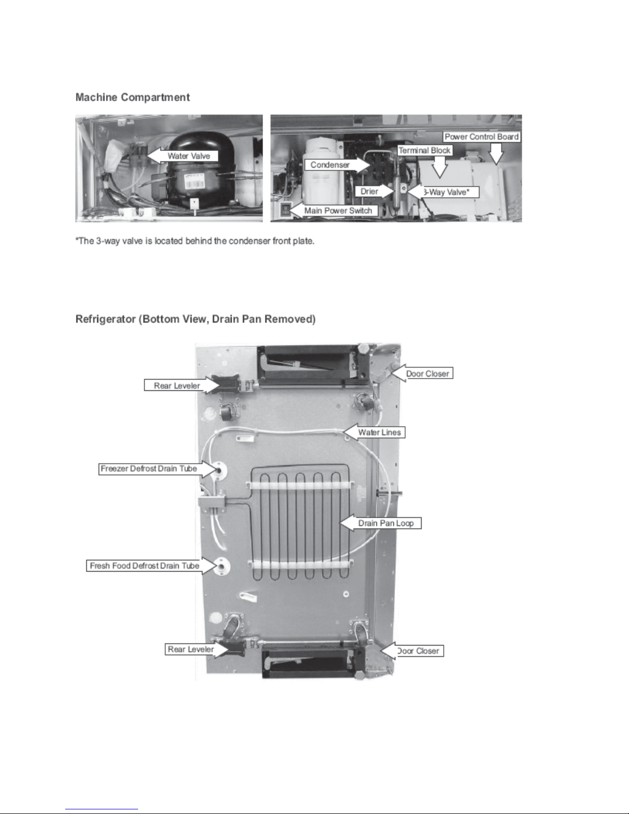
Component Locator Views
Component Locator Views
125995432258
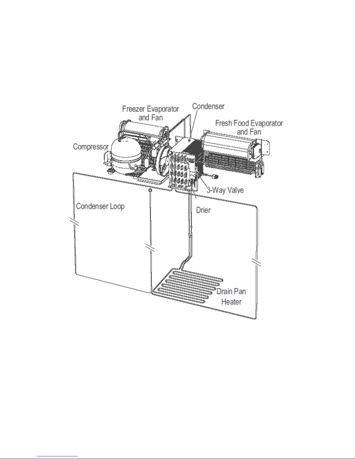
Refrigeration Components
Refrigeration System
13
5995432258

Refrigerant Flow
The compressor compresses R134a refrigerant,
raising its pressure and temperature. Refrigerant
vapor is pumped out the compressor discharge,
down through the drain pan loop, up through
the condenser coil, around the condenser loop,
through the drier, and into the 3-way valve. By
the time the refrigerant has reached the 3-way
valve, it has completely condensed into a liquid.
Depending upon whether the main control board
opens the 3-way valve to the freezer evaporator
or the fresh food and freezer evaporators,
refrigerant fl ows through the appropriate capillary
tube and into the evaporator. As the high pressure
liquid passes through the capillary and enters the
low pressure evaporator, it quickly expands and
evaporates. During evaporation, the refrigerant
absorbs heat, becoming cold. At the outlet of the
freezer evaporator, an accumulator captures any
remaining liquid, allowing only low pressure vapor
to return to the compressor through the suction
line.
145995432258

Note: The refrigerator will operate with the 3-way valve set for freezer only or set for fresh food and
freezer. There is no 3-way valve setting for fresh food only. If the fresh food thermistor is not satisfi ed,
but the freezer thermistor is satisfi ed, the refrigerator will still operate with the 3-way valve set in the
fresh food and freezer mode.
15
5995432258
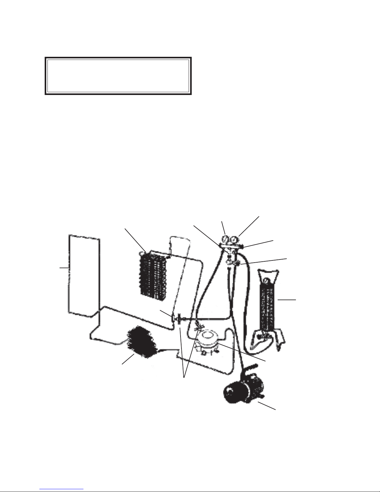
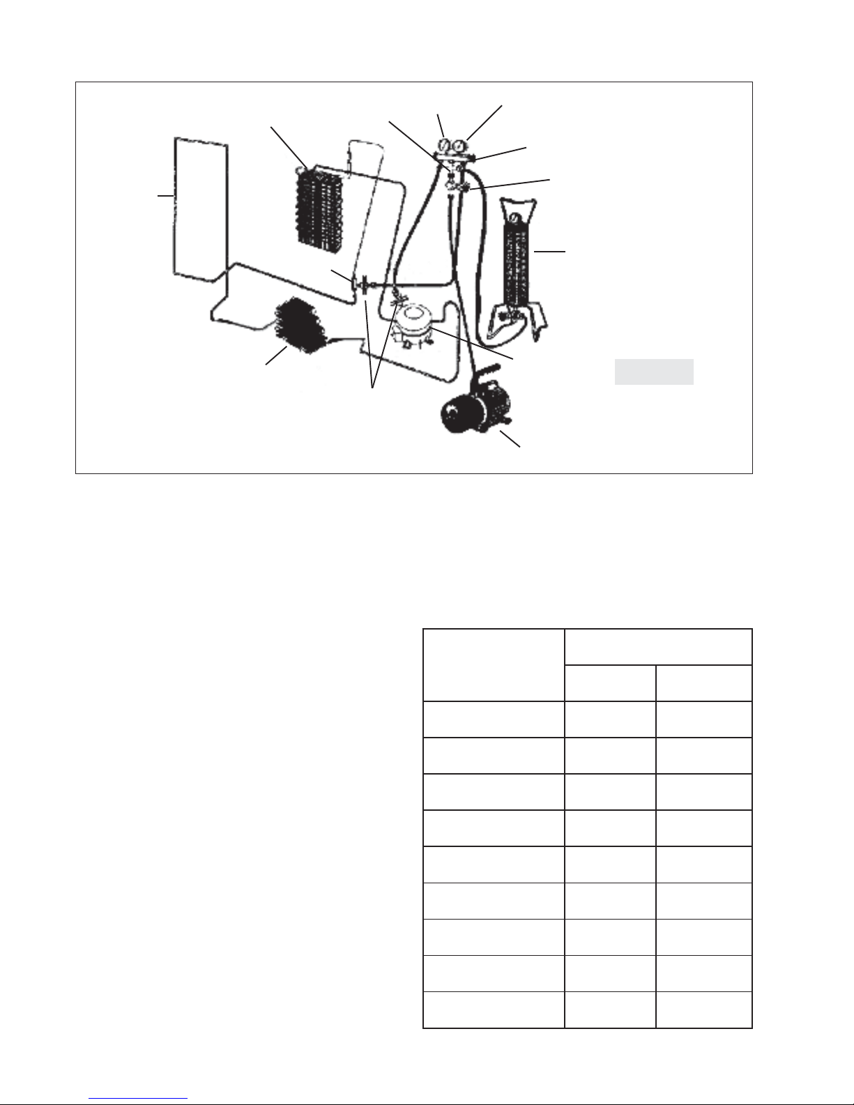
Evacuation and Charging Procedure
Equipment Needed for Evacuation & Recharging:
• Heated charging cylinder
• Standard 3-port manifold gauge set:
4 charging hoses
Tee fitting with valve core stem removed
(Robinair No. 40396)
Hand shut-off valve (Robinair No.40380)
• Two stage vacuum pump
• Process tube adapter kit (Robinair No. 12458)
• Tubing cutter
• Pinch-off tool capable of making leak proof seal
• Complete brazing torch set
• Small 3-corner file
• Grit cloth or Scotch-Brite
• 45% silver solder and flux
Installing Evacuation and Recharging Equipment
1. Disconnect refrigerator from electrical supply.
2. If compressor was replaced, install correct sized
process tube adaptor on process tube. If compressor
was not replaced, cut process tube with tubing cutter
leaving as much tube as possible and install correct
size process tube adaptor.
3. Install correct sized process tube adaptor on
high-side process tube.
4. Attach refrigeration service gauge manifold to
system in following order:
• Low-side (compound gauge) hose to
suction side process tube adaptor.
• High-side (pressure gauge) hose to high-
side process tube adaptor.
• Center port manifold hose before hand
shut-off valve to charging cylinder.
• Center port manifold hose after hand
shut-off valve to vacuum pump.
Evacuating System
WARNING: R-134A SYSTEMS ARE
PARTICULARLY SUSCEPTIBLE TO
MOISTURE CONTAMINATION WHICH CAN
ONLY BE PREVENTED BY EVACUATING THE
SYSTEM FOR A MINIMUM OF 30 MINUTES
TO ATTAIN A MINIMUM 29.9 INCH (500
MICRON OR LOWER) VACUUM.
To achieve the required levels of evacuation, a
properly maintained two stage vacuum pump in good
condition is required. It is absolutely essential to maintain
your vacuum pump according to the manufacturer’s
instructions including required oil changes at the recommended intervals. Vacuum pump oil should always be
changed after evacuating a contaminated system.
Vacuum pump performance should be checked
periodically with a micron gauge.
1. Make certain that charging cylinder valve, hand
shut-off valve, and manifold gauge valves are
closed.
2. Start vacuum pump.
3. Open hand shut-off valve and slowly open both
manifold valves, turning counterclockwise, for
two full rotations.
CAUTION: If high vacuum equipment is
used, just crack both manifold valves for a
few minutes and then open slowly for the
two full turns counterclockwise. This will
prevent the compressor oil from foaming
and being drawn into the vacuum pump.
4. Operate the vacuum pump for a minimum of 30
minutes to a minimum of 29.9” (500 micron)
vacuum.
5. Close hand shut-off valve to vacuum pump.
Watch compound gauge for several minutes. If
reading rises, there is a leak in the system, go to
step 6. If no leak is indicated, stop vacuum pump.
System is now ready for charging.
6. If a leak is indicated, stop vacuum pump and
introduce a small charge of refrigerant into
system by cracking valve on bottom of charging
cylinder until system is pressurized to 40 or 50 l
bs psig.
7. Leak test low-side. Close compound gauge.
Run compressor for a few minutes and leak test
high-side. When leak is found, recapture refrig
erant using EPA approved recovery system
Repair and go back to step 1.
Charging The System
CAUTION: Check the serial plate for the correct refrigerant type. It is extremely important
to verify the type of refrigerant in the system
before starting any sealed system repairs.
CAUTION: After charging the system with
liquid be certain to wait at least 5 minutes
before starting the compressor to give the
refrigerant a chance to disperse throughout
the system. Otherwise the compressor could
be damaged by attempting to pump excessive quantities of liquid.
Preparing The Charging Cylinder:
1. Make certain that hand shut-off valve to vacuum
pump is closed.
2. Close high-side manifold gauge valve.
3. Set charging cylinder scale to pressure indicated
on cylinder pressure gauge.
4. Observe refrigerant level in sight glass. Subtract
amount to be charged into system and note shut
off point.
5. Open charging cylinder valve slowly and allow
proper charge to enter system.
165995432258
6. As soon as refrigerant in sight glass has gone
down to predetermined level, close charging
cylinder valve.
WARNING: DISCONNECT THE CHARGING
CYLINDER HEATER AT THIS TIME TO
PREVENT THE CYLINDER PRESSURE
FROM EXCEEDING ITS MAXIMUM LIMITS.
7. Allow system to sit for five minutes.
8. Turn on refrigerator compressor. Run compres
sor for a few minutes and monitor system
pressures.
9. When satisfied that the unit is operating cor
rectly, clamp the high-side process tube with the
pinch-off tool while the unit is still running.
10.Slowly open the high-side manifold gauge valve
to allow the compressor to remove any refriger
ant trapped in the high-side hose and the process
fitting.
11.Close both of the manifold gauge valves. If the
high-side gauge reading rises, the pinch-off
must be corrected before proceeding.
12.Remove the high-side process tube adaptor
and solder the process tube closed.
13.Clamp the low-side process tube with the pinchoff tool while the unit is running. Remove the
low-side process tube adaptor and solder the
process tube closed.
14.Check the process tubes for refrigerant leaks.
Final leak test
1. With the refrigerator turned OFF leak test all
low-side system components.
2. Turn the unit ON and run until the condenser is
warm. Leak test the high-side system components.
HOT
TUBE
EVAPORATOR
CONDENSER
FILTER
DRIER
TEE
FITTING
PROCESS TUBE
ADAPTERS
COMPOUND
GAUGE
PRESSURE
GAUGE
GAGE
MANIFOLD
HAND SHUTOFF
VALVE
HEATED
CHARGING
CYLINDER
COMPRESSOR
Figure E2
17
2 STAGE VACUUM
PUMP
5995432258
R-134a service information
NOTICE: Instructions given here are furnished as a guide. Persons attempting to use these instructions to make
repairs to the sealed refrigeration system should have a working knowledge of refrigeration and previous training on
sealed system repair.
Verify refrigerant type in the system
CAUTION: R-134a and R-12 are completely
incompatible. Before starting any sealed
system repair, it is extremely important to
check serial plate of product to verify the
type of refrigerant in the system.
Dedicated Equipment
R-134a must not be mixed with other types of
refrigerants. R-134a must be recovered in dedicated and
properly identified recovery bags and tanks.
It will be necessary to check with the manufacturer
of your recovery equipment to determine R-134a
compatibility. Some recovery equipment manufacturers
have changeover instructions for switching between
refrigerant types. Protect yourself and your equipment by
following all manufacturer guidelines.
Also, ensure that your refrigeration hoses are
specified for use with R-134a refrigerant. Research has
shown that compounds in standard refrigeration hoses may
enter sealed systems and ultimately restrict the cap tube
in an R-134a system.
R-134a refrigeration systems
The sealed refrigeration system will consist of the
same basic components being utilized in the R-12 systems.
There is a 10% to 15% discharge pressure increase
using R-134a, with a 5% to 10% decrease in suction
pressure when compared to the same product with an R12 system operating at 90°F (32°C) ambient temperature conditions. Lower suction pressures result from the
lower density of R-134a refrigerant which effects refrigerant flow rate. R-134a systems commonly operate in a 1”2” vacuum on the suction side.
Products using R-134a refrigerant will generally
have a longer capillary tube to maintain a similar flow rate
and some models will have a larger condenser to reduce
the discharge pressures and lower start-up sound transmission.
Miscibility of r-134a and ester oil
A special synthetic oil known as Ester oil is used as
a lubricant in refrigeration systems operating on R-134a.
Ester oils are produced from alcohols and fatty acids
and are available in several different variants. Ester
oils have a pleasant aroma reminiscent of fruit.
Ester oils generally include various types of
additives for improving certain properties such as
viscosity, temperature sensitivity, etc. These additives are
often aggressive, and skin contact with Ester oils should
therefore be avoided.
One of the most important requirements made on a
refrigerant system is that the oil mix with the refrigerant.
Since mineral oil and ordinary synthetic oil DO NOT mix
with R-134a, Ester oil is used for lubrication. Ester oil
dissolves in R-134a.
Ester oil is broken down by chlorine and cannot be
used with R-12 (R-12 contains chlorine) or any other
compound containing chlorine. Therefore, R-134a
refrigeration systems have virtually no tolerance for
chlorine molecules from CFC refrigerants (R-134a is an
HFC and contains no chlorine).
CAUTION: During R-134a service, it is
extremely important to avoid using
equipment that may contain residual amounts
of mineral oil, CFC’s or HCFC’s which could
enter and contaminate the sealed system.
For example, hoses that were used for a refrigeration
system operating on R-12 may contain small quantities of
mineral oil which can block the capillary tube in a system
operating on R-134a. As little as one milligram may be
sufficient to cause a blockage. In addition, sealed system
components that have been used with CFC systems must
not be used with R-134a systems. These components may
contain residual amounts of refrigerant and oil which
could damage an R-134a system.
At the earliest stage of development work on R134a, tests were carried out on a different type of synthetic
oil known as Poly-Alkaline Glycol (PAG). This oil is also
used in certain air conditioning systems for cars. PAG and
Ester oil DO NOT mix with one another. Service equipment used for R-134a / Ester oil must not come into
contact with PAG.
185995432258

Water in the refrigeration system
Even in very small quantities, water in any refrigera-
tion system can cause the following problems:
• Ice plugs in capillary tubes.
• Copper plating in compressor.
• Reactions with organic materials in systems.
• Corrosion of metals.
R-134a and Ester oil will aggravate the problem of
water in the refrigeration system. Ester oil may react with
water vapor and is hydroscopic (it will absorb water if it
comes in contact with humid air). Water is also more
soluble in R-134a than R-12.
2-Stage Vacuum Pump
To minimize the water content whenever service
work is performed, the refrigeration system should always
be thoroughly evacuated through process tube adaptors on
both the high and low sides of the system. Evacuation
must be for a minimum of 30 minutes to at least a 29.9
inch (500 micron) vacuum.
TRAHCMUUCAV
muucaV
.gHsehcnI
snorciM
tnioPgnilioB
F°retaWfo
049.82000529.77
035.92000010.25
238.9200640.23
288.9200010
.1
109.920052.11-
519.920518.23-
719.920012.83-
919.92050.94-
Figure
E3
Vacuum pump maintenance
It is absolutely essential to maintain your vacuum
pump according to the manufacturer’s instructions
including required oil changes at the recommended
intervals. Vacuum pump oil should always be changed
after evacuating a contaminated system. Vacuum pump
performance should be checked periodically with a micron
gauge.
Vacuum pump suppliers may or may not recommend
changing the vacuum pump oil to the same type that’s in
the system being evacuated. Some manufacturers may
recommend a vacuum pump that’s dedicated to R-134a
systems.
Robinair has stated that their current and
discontinued vacuum pump models, using mineral oil
currently specified for use in their vacuum pumps, can be
used to evacuate R-134a/Ester oil systems. Robinair also
states that it is acceptable to alternate between evacuating
R-12/mineral oil and R-134a/Ester oil systems without
adversely effecting the vacuum pump’s performance.
For other brands of vacuum pumps, check with the
manufacturer for restrictions and guidelines when using
with R-134a.
To achieve the required 29.9 inch (500 micron)
vacuum, a properly maintained two-stage vacuum pump in
good condition is required. A two stage pump can reach a
deeper vacuum than a single stage because the exhaust
from the first pumping stage is discharged into the second
pumping stage. This means the second stage begins
pumping at a lower pressure so a lower ultimate vacuum
can be achieved (See 2-Stage Vacuum Pump, Figure E3).
CAUTION: If you use a vacuum pump with
mineral oil to evacuate an R-134a system, it
is ABSOLUTELY ESSENTIAL to have a shutoff valve between pump and your manifold
gauge set as shown in Figure E4. The hand
valve must be closed during all times when
vacuum pump is not operating. This will
prevent migration of mineral oil vapor into
R134a/Ester oil system. If vacuum pump
should stop during evacuation for any reason,
the hand pump shut-off valve must be closed
immediately.
19
5995432258
HOT
TUBE
EVAPORATOR
FILTER
DRIER
TEE
FITTING
COMPOUND
GAUGE
PRESSURE
GAUGE
GAGE
MANIFOLD
HAND SHUTOFF
VALVE
HEATED
CHARGING
CYLINDER
CONDENSER
PROCESS TUBE
ADAPTERS
Evacuating and Recharging Connections
Refrigerant leaks
A system with R-134a and Ester oil will become
saturated with moisture much faster than a system with
R-12 and mineral oil. The compressor in an R-134a system
will have to be replaced if the product has had a low side
leak.
R-134a refrigerant molecules are smaller than R-12
molecules. This means that R-134a will pass more minor
leaks and the rate of flow will be greater than for R-12.
Therefore, it is now more important than ever to follow
good brazing practices. Use a good grade of silver solder.
45% silver solder is recommended.
leak detection
R-134a system leaks can be pinpointed by means of
an electronic leak detector or by bubble solution.
Electronic leak detectors for R-134a service are
currently available from several manufacturers. The least
expensive models are non-selective detectors that will
detect any type of emission or vapor present, regardless of
its chemical composition. Some non-selective detectors
designed for use with R-12 may have a much lower
sensitivity when used with R-134a. However, newly
designed detectors with good R-134a sensitivity are now
available. Be sure to consult with the manufacturer before
selecting or using a non-selective detector with R-134a.
Halogen-specific detectors use a specialized sensor
that allows detection of compounds containing chlorine,
fluorine, bromine, and iodine without being activiated by
other species. The major advantage of this type of detector
is a reduction in the number of “nuisance alarms”.
Halogen-specific detectors are generally more expensive
COMPRESSOR
Figure
E4
2 ST AGE VACUUM
PUMP
than non-selective detectors but feature higher
sensitivity.R-134a properties
R-134a properties
The properties of R-134a are very similar to those of
R12. The principal data for the two refrigerants are shown
in the chart below.
STNAREGIRFER
21-Ra431-R
EMAN
alumroF
)lom/g(thgieWraluceloM
laitnetoPnoitelpeDenozO
)PDO(
laitnetoPgnimraWlabolG
)PWG(
F°tnioPgnilioB
)F°77(erusserPropaV
ytilibammalF
niretaWfoytilibuloS
)F°77@%tw(tnaregirfeR
-oroulfidorolhciD
enahtem
ICC2F
2
39.0213.201
10
1.33.0
6.12-7.51-
gisp08gisp28
enoNenoN
900.011.0
HC
-arteT--2,1,1,1
enahtemoroulf
FC-F
2
3
205995432258
 Loading...