

Electrolux AOW101EABU Installation Manual
STEAM/CONVECTION OVENS MICROWAVE ELECTRIC
6 GN 1/1
260450 260462 260456
260451 260463 260457
°
**
°
**
°
**
400 230 200
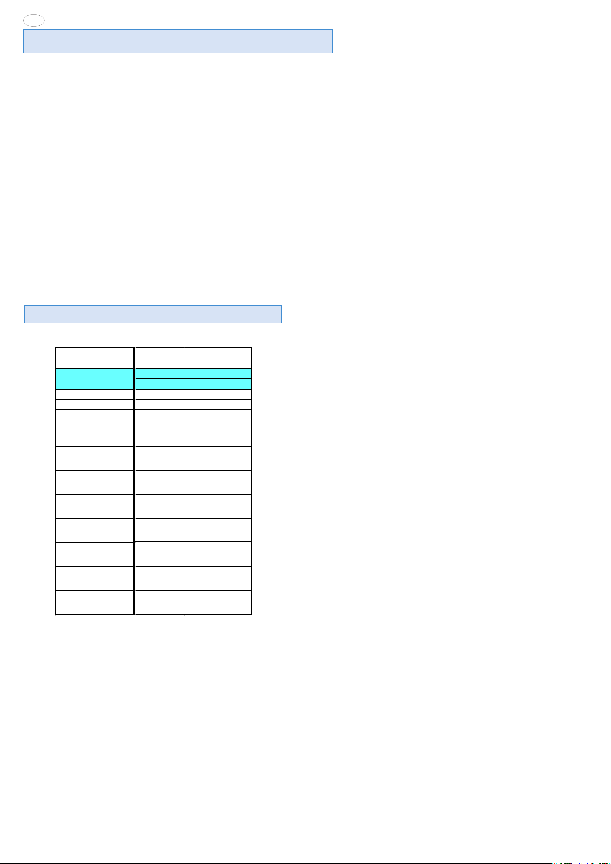
2. TABLE 1: TECHNICAL DATA
INSTALLATION AND OPERATING INSTRUCTIONS(valid for Italy)
Summary Page
- Installation diagrams ........................................................ 8
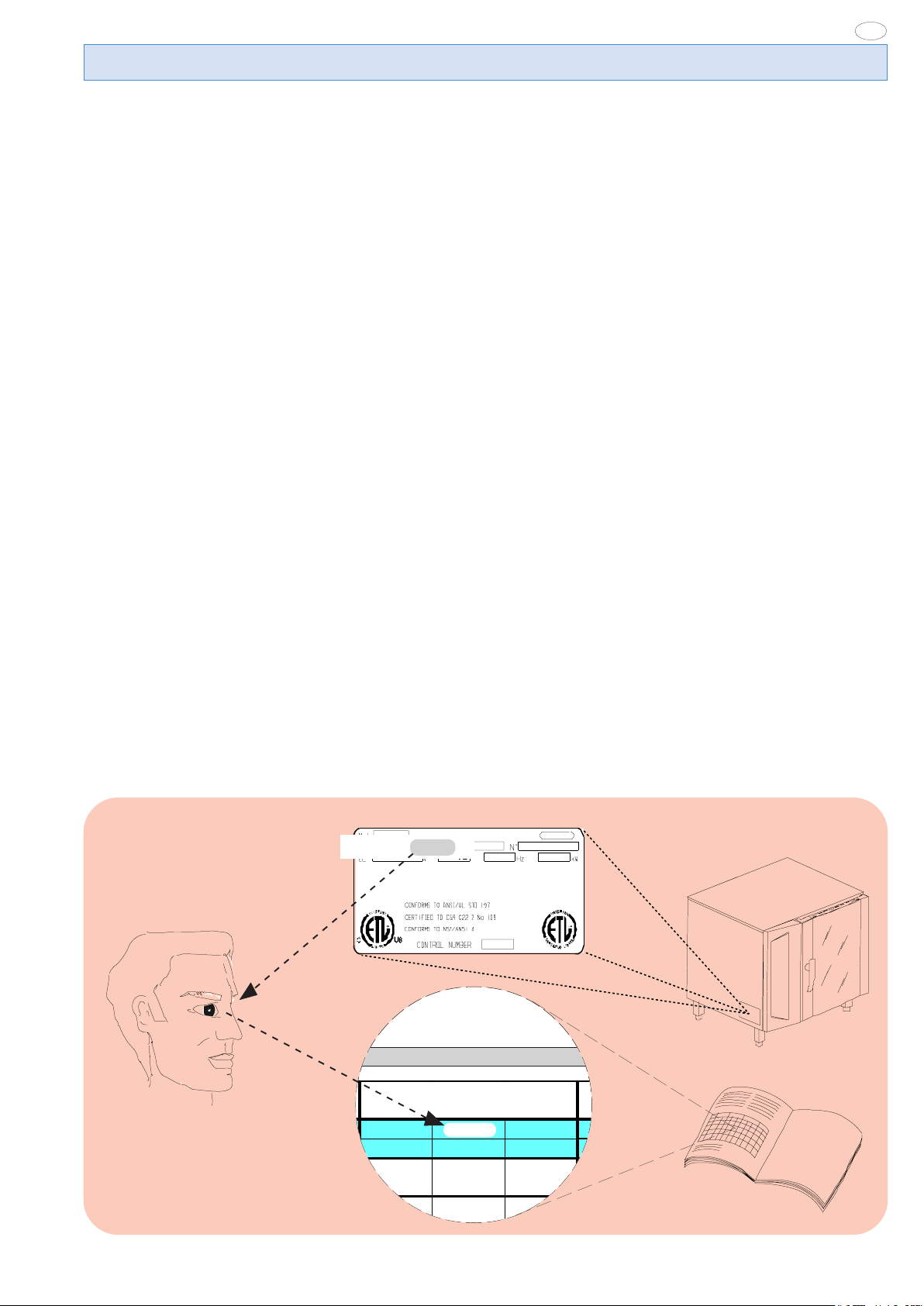
- Appliance identification ................................................. 11
I. GENERAL CHARACTERISTICS ..................................... 12
1. Appliance description ................................................... 12
2. Table 1: Technical data .................................................. 12
3. General instructions ..................................................... 13
4. The environment ............................................................ 14
4.1 Packing..................................................................... 14
4.2 Use ........................................................................... 14
4.3 Cleaning ................................................................... 14
4.4 Disposal ................................................................... 14
II. INSTALLATION INSTRUCTIONS.................................... 15
1. Place of installation ....................................................... 15
1.1 Reference standards ................................................ 15
2. Positioning ..................................................................... 15
3. Electrical connection .................................................... 15
3.1 Power cable installation ............................................ 16
4. Connection to water system ........................................ 16
4.1 Supply water characteristics .................................... 16
4.2 Water drain system .................................................. 16
5. Safety device ................................................................. 17
6. Operation check ............................................................ 17
7. Maintenance ................................................................... 17
8. Brief troubleshooting guide ......................................... 18
9. Position of main components ...................................... 18
III. OPERATING INSTRUCTIONS ....................................... 19
1. Oven door opening ....................................................... 20
1.1 6- and 10-rack models ............................................. 20
2. Oven door closing ......................................................... 20
2.1 6- and 10-rack models ............................................. 20
3. Description of control panel......................................... 20
3.1 Foreword .................................................................. 20
3.2 Basic controls ........................................................... 20
3.3 Main cooking modes ................................................ 21
3.4 Special cooking modes ............................................ 21
3.5 Additional functions .................................................. 22
OVEN USE............................................................................. 23
4. Operating level A ........................................................... 23
4.1 Switching oven on .................................................... 23
4.2 Selecting controls ..................................................... 23
4.3 AUTOMATIC (Automatic control) .............................. 23
4.4 MANUAL (Manual control) ....................................... 25
4.5 Support function settings ......................................... 28
4.6 PROGRAM (Program control) .................................. 29
5. Basic data settings ........................................................ 31
6 Modifying set parameters .............................................. 31
7. Information and errors .................................................. 32
8. Switching off in case of fault........................................ 32
9. Cleaning and maintenance ........................................... 32
9.1 Steam generator periodical maintenance ................ 33
9.2 Replacing consumable components ........................ 33
9.3 Particular cleaning .................................................... 34
EN
- APPLIANCE IDENTIFICATION
- CONTROL PANEL FIGURES ......................................... 107
Rating plate
PNC 9PDX 260462 05
260462
5958 992 00
11
EN
I. GENERAL CHARACTERISTICS
1. APPLIANCE DESCRIPTION
This handbook concerns various appliance models.
For further information regarding your model, refer to Table
1"Technical Data”.
The appliance has the following features:
• Digital indication of temperature.
• Thermostatic probe for measuring the product’s “core” temperature (core probe).
• Constant monitoring of cooking parameters during the entire
cycle.
• Periodical emptying and subsequent automatic washing of the
steam generator to prevent excess scaling.
• Signalling the need for periodical boiler maintenance, see relevant section.
2. TABLE 1: TECHNICAL DATA
• Compartment rapid fume extraction device for gratinating, with
automatic activation.
• AIR-BREAK anti-backflow device for preventing backflow from
the drainage system entering the oven.
• Compartment lighting lamps.
• Door opening double-action safety mechanism to prevent burns.
• Door with double glass: better comfort in the kitchen and low
surface temperatures.
• Cycle for daily cleaning of cooking compartment (CLEANING
SYSTEM) (according to model).
• Self-diagnosis for possible malfunctions by means of signalling
with identification codes (refer to par. “Information and error
codes”.
GRI DS
PNC *
CONVECTO R °
BOILER * *
SUPPLY VOLTAGE
Total W att s
Maximum load capacities
(food)
Net w eight
Shipping we ight
Shipping width
Shipping height
Shipping depth
10GN1/1
(AOW101E)
260573
°
**
208V 3ph
60Hz
64amps
23 kW
110 lbs.
(50 kg)
386 lbs
(175 kg)
430 lbs.
(195 kg)
42 15/16"inch
(1090 mm )
49 5/8"inc h
(1260 mm )
39 9/16"inc h
(1005 mm)
Information on sound emissions: The functional components
of the appliances in question have a noise level not exceeding 70
dB (A).
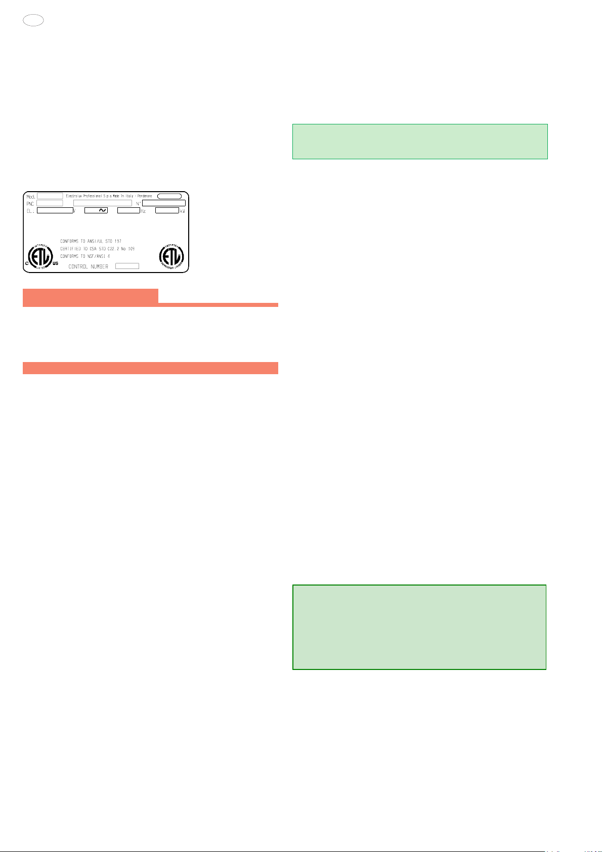
The model of your oven is indicated at the PNC field on the
*
“Technical Data” plate located at the bottom of the left side.
^ OPERATING LEVEL.
5958 992 00
12
EN
3. GENERAL INSTRUCTIONS
• The following terms alert you to potentially dangerous conditions
to the operator, service personnel or to the equipment.
• Danger! This term warns of immediate hazards which will result in
severe injury or death.
• Warning! This term refers to a potential hazard or unsafe
practice which could result in injury or death.
• Notice. This term refers to information that needs special
attention or must be fully understood, even though not dangerous.
• Keep the appliance area free and clear from combustibles.
Warning Fire hazard.
For your safety, do not store or use gasoline or other flammable,
vapors and liquids in the vicinity of this or any other appliance.
Keep area around appliances free and clear of combustibles
Warning!
Failure to properly vent the oven can be hazardous to the health
of the operator; and will result in operational problems,
unsatisfactory baking, and possible damage to the equipment.
Damage sustained as a direct result of improper ventilation will
not be covered by the Manufacturer’s warranty.
WARNING: The equipment warranty is not valid unless the
appliance is installed, started and demonstrated under the supervision
of a factory trained installer.
WARNING: The unit must be installed by Personnel who are
qualified to work with electricity and plumbing. Improper installation
can cause injury to personnel and/or damage to the equipment. The
unit must be installed in accordance with applicable codes.
Important: The installation instructions contained
herein are for the use of qualified installation and
service personnel only. Installation or service by
other than qualified personnel may result in
damage to the appliance and/or injury to the
operator. FAILURE TO COMPLY WITH
INSTALLATION INSTRUCTION OR
IMPROPER INSTALLATION WILL VOID
WARRANTY AND RESPONSIBLITIES OF THE
MANUFACTURE.
NOTICE: INTENDED FOR COMMERCIAL USE ONLY. NOT
FOR HOUSEHOLD USE.
CAUTION HOT SURFACES
CAUTION RISK ELECTRIC SHOCK
CAUTION: Do not locate unit adjacent to any high heat or
grease producing piece of equipment, such as a range top,
griddle, fryer, etc., that could allow radiant heat to raise the
exterior temperature of the Air-O-Steam Oven.
• Before installing and starting the appliance carefully read this
handbook as it provides important information and instructions
on safety, installation, use and maintenance.
• Our appliances have been studied and optimized to give the
highest performance. This appliance is intended for industrial use
only and is specifically designed to cook food. Any other use will be
considered “improper use” and will void the warranty and
manufacturer liability.
WARNING: ANY POTENTIAL USER OF THE EQUIPMENT
SHOULD BE TRAINED IN SAFE AND CORRECT OPERATIONG
PROCEDURES.
WARNING: BEFORE SERVICING, DISCONNET THE
ELECTRICAL SERVICE AND PLACE A RED TAG AT THE
DISCONNECT SWITCH TO INDICATED WORK IS BEING DONE
ON THAT CIRCUIT.
NOTICE: Using any parts other than OEM original spare parts
relieves the manufacturer of all warranty and liability.
• Carefully keep this handbook for further consultation by the
various operators, or in case the appliance is resold.
• The installation of this unit must conform to local codes or, in the
absence of local codes, to all National Codes governing plumbing,
sanitation, safety and good trade practices.
5958 992 00
NOTICE: Manufacturer reserves the right to change specifications
at any time without notice.
Failure to comply with the above requirement may jeopardise
the safety of the appliance and invalidate the guarantee.
13

EN
WARNING: DO NOT SPRAY THE OUTSIDE OF THE
APPLIANCE WITH WATER OR CLEAN WITH A WATER JET.
CLEANING WITH A WATER JET CAN IMPREGNAT
CHLORIDES INTO THE STAINLESS STEEL, CAUSING THE
ONSET OF CORROSION.
WARNING: DO NOT USE PRODUCTS CONTAINING
CHLORINE (BLEACH, HYDROCHLORIC ACID ETC.) EVEN
DILUTED, TO CLEAN STEEL SURFACES.
WARNING: DO NOT USE CORROSIVE SUBSTANCES (E.G.
MURIATIC ACID) TO CLEAN THE FLOOR UNDER THE
APPLIANCE.
4. THE ENVIRONMENT
4.1 PACKING
• All packing materials are environmentally friendly. They can be
stored without risk or burned in a special waste incineration plant.
Recyclable plastic components are marked as follows:
polyethylene : outer wrapping, instruction handbook
PE bag, gas nozzle bag.
polypropylene: roof packing panels, straps
pp
polystyrene foam: corner protectors
PS
4.2 USE
• Our appliances are designed and optimized with laboratory testing in order to offer high performance and efficiency. In any case,
to reduce energy consumption (electricity, gas and water), avoid
using the equipment empty for long periods or in conditions that
compromise optimum efficiency (e.g. door open). Also, if possible, pre-heat the appliance immediately before use.
4.3 CLEANING
• In order to reduce the emission of pollutants into the environment, it is advisable to clean the appliance (externally and when
necessary internally) with products that are more than 90% bio-
degradable %.
4.4 DISPOSAL
• At the end of the appliance’s working life, make sure it is not
dispersed in the environment.
• Our appliances are manufactured using more than 90% metal
materials (stainless steel, iron, aluminum, galvanized sheet, etc.)
which can therefore be recycled by means of the conventional
recovery facilities, in conformity with the current regulations in
the country of use.
• Make the appliance unusable by removing the power cable and
any compartment or cavity closing mechanisms (when present)
in order to avoid the risk of someone becoming closed inside.
14
5958 992 00

II. INSTALLATION INSTRUCTIONS
Important: The external panels of the oven must be
removed for the operations described in this section. As the
unit must be operating in order to carry out some
adjustments, pay maximum attention to the live parts.
1.3 UNPACKAGING
• Remove the appliance from the packaging and take away the
protective film that covers the appliance's external panels carefully to avoid leaving any trace of glue. If necessary remove the glue
using an a non-corrosive solvent, rinsing it off and drying carefully.
• Dispose of packaging material in compliance with the regulations
in force in the country where the product is to be used.
EN
1. PLACE OF INSTALLATION
1.1 VENTILATION
The necessity for a properly designed and installed ventilation
system cannot be over emphasized. The ventilation system will
allow the unit to function properly while removing unwanted vapors
and products of combustion from the operating area.
The appliance must be vented with a properly designed mechanically
driven exhaust hood. The hood should be sized to completely cover
the equipment plus an overhang of a least 6"/15.3cm on all sides not
adjacent to a wall. The capacity of the should be sized appropriately
and provisions for adequate makeup air.
Refer to your local ventilation codes. In the absence of local codes,
refer to the National ventilation code titled, “Standard for the
Installation of Equipment for the Removal of Smoke and Grease
Laden Vapors from Commercial Cooking Equipment”, NFPA-96Latest Edition.
It is recommended that the ventilation system and duct work be
checked at prevailing intervals as specified by the hood manufactured
• The appliance must only be installed in adequately ventilated
premises.
NOTICE: Proper ventilation is the owner's is responsibility. Any
problem due to improper ventilation will not be covered by the
warranty.
1.2 REFERENCE STANDARDS
Note: The electric supply installation must satisfy the requirements
of the appropriate statutory authority, such as the National Electrical
Code (NEC) ANSI/NFPA70, (U.S.A..): the Canadian Electrical
Code, CSA C22.2; or other applicable regulations.
Note: The electric supply connection must meet all national and
local electrical code requirements.
Note: The installation of this unit must conform to local codes or,
in the absence of local codes, to all National Codes governing
plumbing, sanitation, safety and good trade practices, and to the
National Gas Code ANSI Z223.1.
• Local codes regarding installation vary greatle from one area to
another. This equipment is to be installed to comply with the
applicable federal, state or local codes.
The installation instructions contained herein are for the use of
qualified installation and service personnel only. Installation or
service by other than qualified personnel may result in damage to
the appliance and/or injury to the operator.
FAILURE TO COMPLY WITH INSTALLATION INSTRUCTION
OR IMPROPER INSTALLATION WILL VOID WARRANTY AND
RESPONSIBLITIES OF THE MANUFACTURE.
The National Fire Protection Association, Inc states in its NFPA 96
latest edition that local codes are the "authority having jurisdiction"
when it comes to installation requirements for equipment.
Therefore, installations should comply with all local codes.
5958 992 00
1.4 IMMEDIATELY INSPECT FOR SHIPPING DAMAGE
The container should be examined for damage before and during
unloading. The freight carrier has assumed responsibility for its
safe transit and delivery. If damaged equipment is received,
either apparent or concealed, a claim must be made with the
delivering carrier. Apparent damage or loss must be noted on the
freight bill at the time of delivery. The freight bill must then be
signed by the carrier representative (Driver). If the bill is not
signed, the carrier may refuse the claim. The supply can supply
the necessary forms. A request for inspection must be made to
the carrier within 15 days if there is concealed damage or loss that
is not apparent until after the equipment is uncrated. The carrier
should arrange an inspection. Be certain to hold all contents plus
all packing material. Under no circumstances should a damaged
appliance be returned to the manufacturer without prior notice and
written authorization.
2. POSITIONING
• For the overall space required and connection dimensions, refer to the installation diagrams given on the first pages of this
instruction handbook.
• The left, right and top surface of the appliance must remain
at least 23.62" (50cm) from other surfaces to enable maintenance
interventions (if not possible, minimum 1.97" -5cm- is request for
left and right), whereas the back must be at least
1.97" (5cm) from any surface.
• Position the appliance and if necessary adjust the height of the
worktop by means of the adjustable feet.
• The appliance is not suitable for built-in installation.
Important:
Make sure the steam coming from the oven discharge or
adjacent appliances does not reach the special vents for
the cooling of internal components, located at the
bottom of the appliance.
3. ELECTRICAL CONNECTION
• A fused disconnect switch or main circuit breaker (customer
furnished) MUST be installed in the electric supply line for the
appliance. It is recommended that this switch/circuit breaker
have lockout/tagout capability. Before making any electrical
connections to this appliance, check that the power supply is
adequate for the voltage, amperage, and phase requirements
on the rating plate.
• A safety cutout switch of suitable capacity with a contact
breaking distance of at least 3 mm must be fitted upstream of the
appliance.
The cutout switch must be installed near the appliance in the
permanent electrical system of the premises.
15
EN
• The appliance must be electrically grounded in accordance with
local codes, or in the absence of local codes, with the National
Electrical Code, ANSI/NFPA 70, or the Canadian Electrical
Code, CSA C22.2, as applicable.
The grounding conductor must therefore be connected to the
terminal marked Gon the connection terminal board. The
appliance must also be connected to an earth grounding
system.
This connection is made using the stop screw marked E
located on the outside of the appliance near the power cable
inlet.
The grounding wire must have a minimum cross-section of
8 AWG (10 mm
GROUNDING INSTRUCTIONS
This appliance must be connected to a grounded, metallic,
permanent wiring system, or an equipment grounding
conductor should be run with the circuit conductors and
connected to the equipment grounding terminal or lead on
the appliance.
2
).
RATING PLATE
::
:
::
3.1 POWER CABLE INSTALLATION
To connect the power cable to the appliance, proceed as follows:
Model 6 - 10 - 20 GN
• Remove the left side panel.
• Connect the cable to the terminal block as shown in the wiring
diagram attached to the appliance, and secure it with the special
cable gland.
The manufacturer declines any liability if the safety regulations are not respected.
The manufacturer requires when stacking units each appliance
have its own branch circuit protection. An air-o-speed® unit stacked
with an air-o-chill® unit should have a separate circuit breaker for the
upper and lower units.
4.1 SUPPLY WATER CHARACTERISTICS
4.1.1 WATER INLET “N”.
Important (LEVEL A ONLY)
The water supply pipe must have an inside diameter of at
least 20 mm and be free of elbow unions.
The discharge steam condensation system can be fed with cold
water suitable for human consumption, having the following
characteristics:
- total hardness not exceeding 400ppm (40°fH); in LEVEL
A ovens equipped with CLEANING SYSTEM it is advisable to use
water of hardness not exceeding 5° French; for that purpose, a
water softener with automatic regeneration for installing on inlet
line “N” is supplied as an accessory by request.
- pressure between 22 to 36 psi (150-250 kPa); higher
pressures involve waste of water.
Note:
To check correct water installation, make sure the rotating wash
arm (CLEANING SYSTEM) does not turn below 100 rpm (120
max).
4.1.2 WATER INLET “B”.
(With feed pipe supplied)
The inlet for steam production must be fed with water suitable
for human consumption, having specific characteristics:
- total hardness between 5 - 50ppm (0.5 - 5 °fH) French
for reducing scaling inside the steam generator.
For that purpose, a water softener with automatic regeneration
for installing on inlet line “B” is supplied as an accessory by request;
it has a kit for sterilizing the resins (by further request).
- pressure between 22 to 36 psi (150-250 kPa); higher
pressures involve waste of water.
- chlorine concentration (Cl -) not high (acceptable reference value ~10 ppm), so as not to damage the steel structures
inside the oven.
- pH higher than 7.
For that purpose, a special filtering unit for installing on inlet line
“B” is supplied as an accessory by request. The purpose of this
unit is to reduce the water hardness to optimum values (below
50ppm "5 °fH") (optimum value), and therefore also serving as a
water softener.
- electric conductivity between 50 and 2000 µS/cm (68°F)
(20°C).
4. WATER CONNECTION
(See the installation diagrams at the beginning of this handbook)
This equipment is to be installed to comply with the applicable
Federal, State, Local plumbing codes, or the Basic Plumbing
Code of the Building Officials and Code Administrators
International Inc. (BOCA) and Food Service Sanitation Manual
of the Food and Drug Administration (FDA).
The oven has two separate inlets (“B” and “N”) for the supply
water.
The supply pipes of both inlets must be equipped with a mechanical filter and shutoff cock. Before installing the filters, it is
advisable to let a certain amount of water flow in order to clean
the pipe of any solid particles.
Important: The use of water treatment systems utilizing
methods different from those indicated by the manufacturer of
the equipment is not allowed and will completely invalidate the
warranty.
Likewise, dispensers of substances for preventing scale in
the pipes (e.g. polyphosphate dispensers) must not be
used because they can compromise correct machine
operation.
4.2 WATER DRAINING SYSTEM
The oven has an AIR-BREAK anti-backflow device inside to prevent possible backflow from the drainage system entering the
internal pipes and the oven compartment. This allows the drain
pipe to be connected directly to the mains system or discharging
into a floor grate.
The drain pipe (rigid or flexible type) can be run to the side or
16
5958 992 00
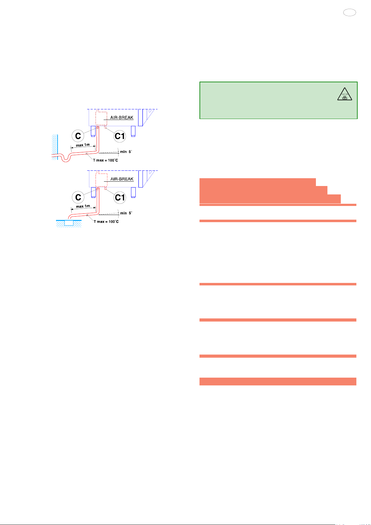
back if the oven is not placed against a wall, excluding the front
part with rack support structure. It must not be more than 3 feet
(1 metre) long, with inside diameter not less than that of the
oven discharge pipe (1" 1/4), and must withstand temperatures
of at least 212°F (100°C). Make sure there are no constrictions in
hoses or elbows in metal pipes, along the entire drain path. Avoid
horizontal sections where water can collect and stagnate (min.
slope 5%).
WARING: BLOCKING THE DRAIN IS HAZARDOUS.
C - Oven drain
C1 - Safety outlet
Important:
- Do not obstruct the safety outlet C1.
- Do not connect the safety outlet C1 to the drainage system.
Note:
If water comes out of the AIR-BREAK (safety outlet C1) this means
the drain C is blocked. Any elimination of the obstruction must
be carried out by specialized technical personnel.
5. SAFETY DEVICE
The appliance is equipped with the following safety devices:
- Fuses, see the wiring diagram, located behind the control panel.
For replacement, unscrew the holding cap and replace the damaged component with another one of equal capacity; this value is
indicated on the rating plate located in the same place.
- Compartment manual-reset safety thermostat located behind the control panel; it intervenes, cutting off the convection
heating supply.
RESETTING OPERATIONS MUST BE CARRIED OUT BY
SPECIALIZED TECHNICAL PERSONNEL AFTER ELIMINATING
THE CAUSES OF INTERRUPTION.
- Automatic-reset thermal device inside the fan motor, which
intervenes in case the motor overheats, protecting equipment
operation; it intervenes, cutting off the electric power to the appliance.
- MAGNETRON manual-reset safety thermostat located behind the left side panel; it intervenes, cutting off the power supply
to the MAGNETRON.
Resetting operations must be carried out by specialized technical personnel after eliminating the causes of interruption.
5958 992 00
EN
6. OPERATION CHECK
- Switch the appliance on, following the instructions in the section “Operating instructions”;
- Explain appliance operation, routine maintenance and cleaning
operations to the user, with the help of the instruction handbook.
Important:
- During operation, pay attention
to the hot zones of the exterior surface.
- Do not place objects on the outlets located at the top
of the appliance.
- With oven hot, check the correct working of the door closing
mechanism. If necessary, adjust closing by adjusting the position
of the catch.
7. MAINTENANCE
PRECAUTION TO BE OBSERVED BEFORE
AND DURING SERVICING TO AVOID POSSIBLE
EXPOSURE TO EXCESSIVE MICROWAVE ENERGY
(a) Do not operate or allow the oven to be operated with
the door open.
(b) Make the following safety checks on all ovens to be
serviced before activating the magnetron or other
microwave source, and make repairs as necessary:
(1) interlock operation,
(2) proper door closing,
(3) seal and sealing surfaces (arcing, wear, and other
damage),
(4) damage to or loosening of hinges and latches,
(5) evidence of dropping or abuse.
(c) Before turning on microwave power for any service
test or inspection within the microwave generating
compartments, check the magnetron, wave guide or
transmission line, and cavity for proper alignment,
integrity, and connection.
(d) Any defective or misadjusted components in the
interlock, monitor, door seal, and microwave generation
and transmission systems shall be repaired, replaced, or
adjusted by procedures described in this manual before
the oven is released to the owner.
(e) A microwave leakage check to verify compliance with
the Federal Performance Standard should be performed
on each oven prior to release to the owner.
The components requiring routine maintenance are accessible
by opening the control panel, and the left, right and rear panels.
Danger: Live voltage is present with panels removed and unit
switch on. Exercise extreme caution when work with live voltage.
NOTICE: Using any parts other than OEM original spare parts
relieves the manufacturer of all warranty and liability.
::
:
::
17

EN
8. BRIEF TROUBLESHOOTING GUIDE
Even with correct use, malfunctions can occur.
Oven compartment heating does not switch on or is inefficient. Possible causes:
- Oven compartment temperature limiter activated
- Heating elements damaged
- Element contactor coil damaged
- Oven compartment temperature probe damaged (error EPt1 configuration).
- Controller damaged
- Fuse F2 blown, see wiring diagram.
- MAGNETRON limiters activated.
The steam generator heating does not switch on or is inefficient in steam production. Possible causes:
- Heating elements damaged
- Element contactor coil damaged
- Controller damaged
- Fuse F2 blown
- No water in system
- Boiler drain closing device faulty
- Water inlet solenoid valves damaged (they do not open)
Incorrect oven compartment temperature thermostatting.
Possible causes:
- Electronic controller faulty.
- Oven compartment temperature probe dirty, faulty or disconnected, see error EPt1 configuration.
The oven goes off. Possible causes:
- Fuse F2 blown due to damaged auxiliary circuit components.
Oven compartment lamps damaged
Important: Switch the appliance off before changing oven com-
partment lamps.
9. POSITIONING OF MAIN COMPONENTS
(Any operation inside the appliance must only be carried out
by an installer authorized by the Manufacturer)
Open the control panel to access the following components:
Danger: Live voltage is present with panels removed and unit
switch on. Exercise extreme caution when work with live voltage.
- Electronic boards.
- Compartment temperature limiter thermostat.
- Fuses.
- Door safety microswitch.
- Transformer for compartment lamps
- Compartment vent shutter control gear motor
WARNING: Before servicing unit switch off power at the main
circuit breaker and place a red tag on the breaker to indicate work
is being done on the circuit.
Remove the appliance left, right and rear panels to access to all
the other components.
18
5958 992 00
 Loading...