

Page 1
USA
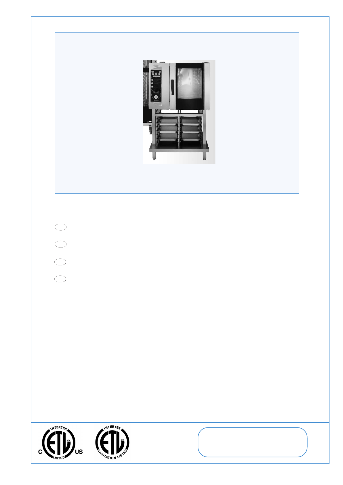
- ELECTRICS HEATED MICROWAVE STEAM CONVECTION OVENS
INSTALLATION, OPERATION AND MAINTENANCE Page 11
IT
- FORNI CONVEZIONE/VAPORE MICROONDE ELETTRICI
INSTALLAZIONE, USO E MANUTENZIONE Pagina 35
- FOURS À CONVECTION/VAPEUR MICRO-ONDES ÉLECTRIQUES
CDN
INSTALLATION, UTILISATION ET ENTRETIEN Page 59
- HORNOS MICROONDAS DE CONVECCIÓN Y VAPOR ELECTRICOS
ES
INSTALACIÓN, USO Y MANTENIMIENTO Pág. 83
DOC. NO. 5958 992 00
EDITION 1 E 0410 LA
From the Electrolux Group
Page 2

USA
When using electrical appliances basic safety precautions should be followed, including the following:
WARNING - To reduce the risk of burns, electric shock, fire, injury to persons, or exposure to excessive microwave energy:
1) Read all instructions before installing and using the appliance.
2) Read and follow the specific "PRECAUTIONS TO AVOID POSSIBLE EXPOSURE TO EXCESSIVE MICROWAVE ENERGY"
found on (see section III.).
3) This appliance must be grounded. Connect only to properly grounded outlet. See "GROUNDING INSTRUCTIONS" found
on (see paragraph 7. - section II.).
4) Install or locate this appliance only in accordance with the provided installation instructions.
5) Some products such as whole eggs and sealed containers - for example, closed glass jars - are able to explode and
should not be heated in this oven.
6) Use this appliance only for its intended use as described in the manual. Do not use corrosive chemicals or vapors in
this appliance. This type of oven is specifically designed to heat, cook, or dry food. It is not designed for industrial or
laboratory use.
7) As with any appliance, close supervision is necessary when used by children.
8) Do not operate this appliance if it has a damaged cord or plug, if it is not working properly, or if it has been damaged or
dropped.
9) This appliance should be serviced only by qualified service personnel. Contact nearest authorized service facility for
examination, repair, or adjustment.
10) Do not cover or block any openings on the appliance.
IMPORTANT SAFETY INSTRUCTIONS
11) Do not store this appliance outdoors. Do not use this product near water - for example, near a kitchen sink, in a wet
basement, near a swimming pool, or similar locations.
12) Do not immerse cord or plug in water.
13) Keep cord away from heated surfaces.
14) Do not let cord hang over edge of table or counter.
15) See door surface cleaning instructions on (see paragraph 7. - section III.).
16) To reduce the risk of fire in the oven cavity:
i) Do not overcook food. Carefully attend appliance when paper, plastic, or other combustible materials are placed inside
the oven to facilitate cooking.
ii) Remove wire twist-ties from paper or plastic bags before placing bag in oven.
iii) If materials inside the oven ignite, keep oven door closed, turn oven off, and disconnect the power cord, or shut off
power at the fuse or circuit breaker panel.
iv) Do not use the cavity for storage purposes. Do not leave paper products, cooking utensils, or food in the cavity when
not in use.
17) Liquids, such as water, coffee, or tea are able to be overheated beyond the boiling point without appearing to be boiling.
Visible bubbling or boiling when the container is removed from the microwave oven is not always present. THIS COULD
RESULT IN VERY HOT LIQUIDS SUDDENLY BOILING OVER WHEN THE CONTAINER IS DISTURBED OR A UTENSIL
IS INSERTED INTO THE LIQUID.
18) Don't install the oven on the free-standing support (for CANADA only).
SAVE THESE INSTRUCTION
Do not store or use gasoline or other flammable vapors or liquids in the vicinity of this or any other appliance.
WARNING: Improper installation, adjustment, alteration, service or maintenance can cause property damage,
injury or death. Read the installation, operating and maintenance instructions thoroughly before installing or
servicing this equipment.
2
5958 992 00
Page 3

IT
Durante l'uso di apparecchiature elettriche, si raccomanda di seguire le misure generali di sicurezza, incluse le seguenti:
AVVERTENZA - Per ridurre il rischio di ustioni, scosse elettriche, incendi, lesioni alle persone o eccessiva esposizione
all'energia delle microonde:
1) Leggere tutte le istruzioni prima di installare e utilizzare l'apparecchio.
2) Leggere e seguire le "PRECAUZIONI PER EVITARE L'ESPOSIZIONE ALLA ENERGIA ECCESSIVA DELLE MICROONDE",
riportata alla sezione III).
3) Questa apparecchiatura deve essere collegata alla messa a terra. Collegare l'apparecchio solo ad una presa
adeguatamente collegata alla messa a terra. Vedere le "ISTRUZIONI PER IL COLLEGAMENTO DI MESSA A TERRA"
al paragrafo 7 - sezione II).
4) Installare o posizionare l'apparecchio solo in conformità alle istruzioni di installazione fornite.
5) Alcuni prodotti, come uova intere e contenitori sigillati, (ad esempio, barattoli di vetro chiusi) potrebbero esplodere e
non devono essere riscaldati nel forno.
6) Utilizzare questo apparecchio solo per l'uso a cui è destinato, come descritto in questo manuale. Non utilizzare sostanze
chimiche o vapori corrosivi all'interno dell'apparecchio. Questo tipo di forno è progettato specificatamente per
riscaldare, cuocere o essicare alimenti. Non è designato per usi industriali o di laboratorio.
7) Come per ogni altro apparecchio, l'uso di questo prodotto da parte dei bambini è soggetto a rigido controllo degli adulti.
8) Non mettere in funzione l'apparecchio in presenza di una spina o un cavo danneggiati, o dopo malfunzionamenti
dell'apparecchio o in seguito a caduta o danni di qualsiasi tipo.
9) Le operazioni di assistenza per questo prodotto devono essere eseguite esclusivamente da personale professionalmente qualificato. Contattare la società autorizzata per l'assistenza per le operazioni di ispezione, riparazione e
regolazione.
ISTRUZIONI IMPORTANTI PER LA SICUREZZA
10) Non coprire o ostruire le aperture dell'apparecchiatura.
11) Non conservare questo apparecchio all'esterno. Non usare l'apparecchio in prossimità di acqua, ad esempio, vicino
ad un lavello, in un seminterrato, in una piscina o ambiente simile.
12) Non immergere il cavo o la spina di alimentazione in acqua.
13) Tenere il cavo lontano da superfici riscaldate.
14) Non lasciar pendere il cavo oltre il bordo del tavolo o del piano.
15) Vedere le istruzioni relative alla pulizia della superficie (paragrafo 7, sezione III).
16) Per ridurre il rischio di incendio nella cavità del forno:
i) Non cuocere troppo a lungo gli alimenti. Sorvegliare l'apparecchio con attenzione se si introduce carta, plastica o
altro materiale combustibile all'interno del forno per facilitare la cottura.
ii) Rimuovere i legacci metallici per la chiusura dei sacchetti di carta o plastica, prima di introdurre i sacchetti nel forno.
iii) Se il materiale all'interno del forno si incendia, lasciare chiusa la porta, spegnere il forno e scollegare la spina di
alimentazione oppure togliere l'elettricità al fusibile o all'interruttore di circuito.
iv) Non utilizzare la cavità del forno per conservare alimenti. Non lasciare prodotti di carta, utensili o cibi nella cavità
del forno quando questo non è in uso.
17) Alcuni liquidi come acqua, caffè o tè potrebbero surriscaldarsi senza che siano visibili i segni di ebollizione. I segni tipici
dell'ebollizione, come le bollicine, non sono sempre evidenti quando si rimuove il contenitore dal forno a microonde.
QUESTO POTREBBE COMPORTARE LA FUORIUSCITA DI LIQUIDI MOLTO CALDI QUANDO IL CONTENITORE VIENE
MOSSO OPPURE UN UTENSILE VIENE INTRODOTTO NEL LIQUIDO.
18) Non installare il forno sul supporto autoportante (Solo per il CANADA).
CONSERVARE QUESTE ISTRUZIONI
Non immagazzinare o usare benzina o altri materiali infiammabili o liquidi nelle vicinanze di questa o qualsiasi
altra apparecchiatura.
AVVERTENZA: Installazione impropria, adattamenti, modifiche o manutenzione possono causare danni alla
proprieta` o morte. Leggere attentamente le istruzioni per l'installazione, il funzionamento e la manutenzione prima di
installare questa apparecchatura.
5958 992 00
3
Page 4

CDN
CDN
Lors de l'utilisation d'appareils électriques, il est recommandé d'observer les consignes de sécurité fondamentales suivantes:
AVERTISSEMENT - Pour réduire les risques de brûlures, de décharge électrique, d'incendie, de blessures corporelles ou
d'exposition à une énergie de micro-ondes excessive :
1) Lire toutes les instructions avant d'installer et d'utiliser l'appareil.
2) Lire et observer les "PRÉCAUTIONS À PRENDRE POUR ÉVITER L'EXPOSITION À UNE ÉNERGIE DE MICRO-ONDES
EXCESSIVE" (voir section III.).
3) Cet appareil doit être mis à la terre. Branché seulement sur une prise correctement mise à la terre. Voir "Instructions
pour la mise à la terre" (voir paragraphe 7. - section II.).
4) Installer cet appareil en respectant les instructions d'installation fournies.
5) Certains produits comme, par exemple, des œufs entiers et des récipients hermétiquement fermés - pots de verre
fermés - risquent d'exploser et ne doivent donc pas être réchauffés dans le four.
6) Utiliser cet appareil seulement pour l'utilisation prévue tel que décrit dans le présent manuel. Ne pas utiliser de vapeurs
ou de produits chimiques corrosifs dans cet appareil. Ce type de four est spécialement conçu pour chauffer, cuire ou
sécher les aliments. Il n'est pas conçu pour un usage industriel ou de laboratoire.
7) Comme avec tout appareil, l'étroite supervision d'un adulte est nécessaire si le four est utilisé par des enfants.
8) Ne pas faire fonctionner cet appareil si sa prise ou son cordon électrique est endommagé, s'il ne fonctionne pas bien
ou s'il est tombé ou endommagé.
9) Cet appareil ne doit être réparé que par un personnel qualifié. Pour tout réglage, révision ou réparation, contacter le
réparateur agréé le plus proche.
CONSIGNES DE SÉCURITÉ IMPORTANTES
10) Ne pas couvrir ou bloquer les orifices d'évacuation de l'appareil.
11) Ne pas ranger cet appareil à l'extérieur. Ne pas utiliser ce produit près d'un point d'eau - par exemple, à proximité d'un
évier, dans une cave humide, à proximité d'une piscine ou d'autres installations de ce type.
12) Ne pas plonger le cordon ou la prise électrique dans de l'eau.
13) Tenir le cordon d'alimentation loin des surfaces chaudes.
14) Ne pas laisser le cordon pendre sur le bord de la table ou du comptoir.
15) Se reporter aux instructions de nettoyage de la surface de la porte (voir paragraphe 7. - section III.).
16) Pour réduire les risques d'incendie dans la cavité du four :
i) Ne pas trop faire cuire les aliments. Surveillez l'appareil si vous utilisez du papier, du plastique ou toute autre matière
combustible à l'intérieur du four pour faciliter la cuisson.
ii) Retirer les liens torsadés des sachets en papier ou en plastique avant de placer ceux-ci dans le four.
iii) Si des matériaux prennent feu à l'intérieur du four, laisser la porte fermée, éteindre le four et débrancher le cordon
électrique ou couper le courant à partir du tableau des fusibles ou disjoncteurs.
iv) Ne pas utiliser la cavité du four pour ranger des objets. Ne pas laisser de produits de papier, d'ustensiles de cuisson
ou d'aliments dans la cavité du four lorsqu'il n'est pas utilisé.
17) Ne pas faire trop réchauffer les liquides, comme l'eau, le café ou le thé pour éviter l'effet d'ébullition à retardement.
L'ébullition n'est pas toujours visible au moment où le récipient est sorti du four micro-ondes. L'ÉBULLITION PEUT ÊTRE
À RETARDEMENT ET SOUDAINE AU MOMENT OÙ LE RÉCIPIENT EST BOUGÉ OU LORSQU'UN USTENSILE EST
INTRODUIT DANS LE LIQUIDE.
18) Ne pas installer le four sur le pied autoportant (pour le CANADA seulement).
CONSERVER CES INSTRUCTIONS
Il ne faut pas emmagasiner ou utiliser l’essence ou d’autres matériaux inflammables ou liquides à côté de cet
appareil ou d’autres appareils.
AVERTISSEMENT: L’installation, l’adaptation, la modification et l’entretien inadéquats peuvent causer des
dommages aux structures ou aux personnes et la mort. Lire attentivement les instructions d’installation, de fonctionnement
et d’entretien avant d’installer cet appareil.
4
5958 992 00
Page 5

ES
Se deben seguir las precauciones básicas de seguridad al usar aparatos eléctricos, incluyendo las siguientes:
ADVERTENCIA: Para reducir el riesgo de quemaduras, choque eléctrico, incendio, lesiones a personas o exposición a la
energía excesiva de microondas:
1) Lea todas las instrucciones antes de instalar y usar el aparato.
2) Lea y siga las "PRECAUCIONES PARA EVITAR UNA POSIBLE EXPOSICIÓN A LA ENERGÍA EXCESIVA DE MICROONDAS"
3) Este aparato debe tener conexión a tierra. Conéctelo únicamente a un tomacorriente con adecuada conexión a tierra.
4) Instale o ubique este aparato solamente de acuerdo con las instrucciones de instalación provistas.
5) Algunos productos, tales como huevos enteros y recipientes sellados – por ej., frascos de vidrio cerrados – pueden
6) Use este aparato únicamente para el uso previsto descrito en el manual. No use agentes químicos ni vapores corrosivos
7) Como con cualquier aparato, es necesaria una rigurosa supervisión si este está en manos de niños.
8) No opere este aparato si tiene un cable o un enchufe dañado, si no está funcionando adecuadamente o si está dañado
9) Las tareas de servicio de este aparato deben ser realizadas únicamente por personal de servicio calificado. Póngase
IMPORTANTES INSTRUCCIONES DE SEGURIDAD
específicas detalladas (ver sección III.).
Consulte las "INSTRUCCIONES PARA CONEXIÓN A TIERRA" detalladas (ver párrafo 7. - sección II.).
explotar y no deben ser calentados en este horno.
en este aparato. Este tipo de horno está especialmente diseñado para calentar, cocinar o secar comida. No está
diseñado para uso industrial o de laboratorio.
o se ha caído.
en contacto con el centro de servicios autorizado más cercano para inspección, reparación o ajustes.
10) No cubra ni bloquee las aberturas de este aparato.
11) No almacene este aparato al aire libre. No use este producto cerca del agua – por ej., cerca del vertedero de la cocina,
en un sótano húmedo, cerca de una alberca o lugares similares.
12) No sumerja el cable ni el enchufe en agua.
13) Mantenga el cable alejado de superficies calientes.
14) No permita que el cable cuelgue sobre el borde de la mesa o de la superficie de trabajo.
15) Consulte las instrucciones de limpieza para la superficie de la puerta (ver párrafo 7. - sección III.).
16) Para reducir el riesgo de incendio en la cavidad del horno:
i) No cocine comida por demás. Esté cuidadosamente atento al colocar papel, plástico u otros materiales combustibles
dentro del horno para facilitar la cocción.
ii) Retire los alambres de sujeción de bolsas de papel o plástico antes de colocar la bolsa en el horno.
iii) Si los materiales que están dentro del horno se incendian, mantenga la puerta cerrada, apague el horno y desconecte
el cable de alimentación o interrumpa la alimentación en el panel de fusibles o interruptor de circuito.
iv) No use la cavidad como lugar de almacenamiento. No deje productos de papel, utensilios de cocina ni comida en la
cavidad cuando no la esté usando.
17) Los líquidos, tales como agua, café o té se pueden sobrecalentar más allá del punto de ebullición sin que parezca que
han hervido. No siempre se presenta un burbujeo o ebullición visible al retirar un recipiente del horno microondas. ESTO
PUEDE CAUSAR EL DESBORDE DE LÍQUIDOS MUY CALIENTES AL MOVER EL RECIPIENTE O AL INSERTAR UN
UTENSILIO EN EL LÍQUIDO.
18) No instale el horno sobre el soporte independiente (únicamente para CANADÁ).
CONSERVE ESTAS INSTRUCCIONES
No almacenar o utilizar gasolina u otros materiales inflamables o líquidos cerca de este u otros aparatos.
ADVERTENCIA: Una instalación indacuada, lo mismo que modificaciones y operaciones de mantenimiento
incorrectas pueden causar daños a la estructura y a las personas y provocar la muerte. Antes de instalar el aparato leer con
mucha atención las instrucciones de la instalación, del funcionamiento y del mantenimiento.
5958 992 00
5
Page 6

USA
INSTALLATION DIAGRAM
IT
SCHEMI DI INSTALLAZIONE
CDN
SCHEMAS D'INSTALLATION
ES
ESQUEMA PARA LA INSTALACIÓN
5958 992 00
6
Page 7

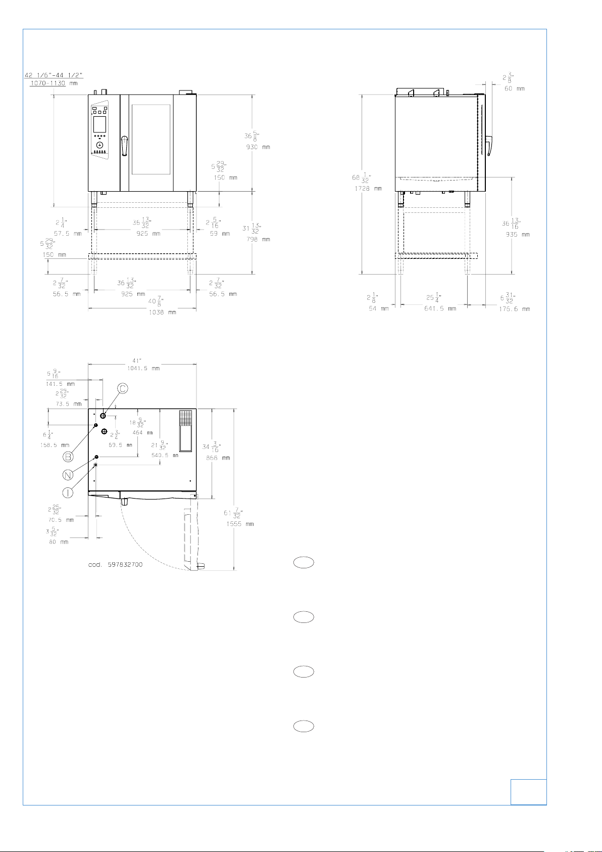
IN THE NEXT PICTURE
USA
I - Power supply cable inlet
B - Water supply connection (0.5- 5 °F) ø3/4" water conn.
C - Water drain connection ø1"1/4 NPT gasline
N - Steam condens. water connection ø3/4" water conn.
IT
I - Entrata cavo elettrico
B - Attacco alim. acqua (0,5 - 5 °F) ø3/4" water conn.
C - Collettore scarico acqua ø1"1/4 NPT gasline
N - Attacco acqua Conden. fumane ø3/4" water conn.
CDN
I - Entrée câble électrique
B - Entrée eau (0,5 - 5 °F) ø3/4" water conn.
C - Collecteur évacuation eau ø1"1/4 NPT gasline
N - Entrée eau Conden.vapeurs ø3/4" water conn.
ES
I - Ingreso cable eléctrico
B - Conexión de agua (0,5 - 5 °F) ø3/4" water conn.
C - Colector del desagüe ø1"1/4 NPT gasline
N - Entrada del agua de condensación ø3/4" water conn.
5958 992 00
1a
7
Page 8
Mod.: 10 GN 1/1
USA
I - Power supply cable inlet
B - Water supply connection (0.5- 5 °F) ø3/4" water conn.
C - Water drain connection ø1"1/4 NPT gasline
N - Steam condens. water connection ø3/4" water conn.
IT
I - Entrata cavo elettrico
B - Attacco alim. acqua (0,5 - 5 °F) ø3/4" water conn.
C - Collettore scarico acqua ø1"1/4 NPT gasline
N - Attacco acqua Conden. fumane ø3/4" water conn.
CDN
I - Entrée câble électrique
B - Entrée eau (0,5 - 5 °F) ø3/4" water conn.
C - Collecteur évacuation eau ø1"1/4 NPT gasline
N - Entrée eau Conden.vapeurs ø3/4" water conn.
ES
I - Ingreso cable eléctrico
B - Conexión de agua (0,5 - 5 °F) ø3/4" water conn.
C - Colector del desagüe ø1"1/4 NPT gasline
N - Entrada del agua de condensación ø3/4" water conn.
1b
5958 992 00
8
Page 9

IN THE NEXT PICTURE
USA
I - Power supply cable inlet
B - Water supply connection (0.5- 5 °F) ø3/4" water conn.
C - Water drain connection ø1"1/4 NPT gasline
N - Steam condens. water connection ø3/4" water conn.
IT
I - Entrata cavo elettrico
B - Attacco alim. acqua (0,5 - 5 °F) ø3/4" water conn.
C - Collettore scarico acqua ø1"1/4 NPT gasline
N - Attacco acqua Conden. fumane ø3/4" water conn.
CDN
I - Entrée câble électrique
B - Entrée eau (0,5 - 5 °F) ø3/4" water conn.
C - Collecteur évacuation eau ø1"1/4 NPT gasline
N - Entrée eau Conden.vapeurs ø3/4" water conn.
ES
I - Ingreso cable eléctrico
B - Conexión de agua (0,5 - 5 °F) ø3/4" water conn.
C - Colector del desagüe ø1"1/4 NPT gasline
N - Entrada del agua de condensación ø3/4" water conn.
5958 992 00
1c
9
Page 10

NO TEXT ON THIS PAGE
10
5958 992 00
Page 11
STEAM/CONVECTION OVENS MICROWAVE ELECTRIC
6 GN 1/1
260450 260462 260456
260451 260463 260457
°
**
°
**
°
**
400 230 200
2. TABLE 1: TECHNICAL DATA
INSTALLATION AND OPERATING INSTRUCTIONS(valid for Italy)
Summary Page
- Installation diagrams ........................................................ 8
- Appliance identification ................................................. 11
I. GENERAL CHARACTERISTICS ..................................... 12
1. Appliance description ................................................... 12
2. Table 1: Technical data .................................................. 12
3. General instructions ..................................................... 13
4. The environment ............................................................ 14
4.1 Packing..................................................................... 14
4.2 Use ........................................................................... 14
4.3 Cleaning ................................................................... 14
4.4 Disposal ................................................................... 14
II. INSTALLATION INSTRUCTIONS.................................... 15
1. Place of installation....................................................... 15
1.1 Reference standards ................................................ 15
2. Positioning ..................................................................... 15
3. Electrical connection .................................................... 15
3.1 Power cable installation ............................................ 16
4. Connection to water system ........................................ 16
4.1 Supply water characteristics .................................... 16
4.2 Water drain system .................................................. 16
5. Safety device ................................................................. 17
6. Operation check ............................................................ 17
7. Maintenance................................................................... 17
8. Brief troubleshooting guide ......................................... 18
9. Position of main components ...................................... 18
III. OPERATING INSTRUCTIONS ....................................... 19
1. Oven door opening ....................................................... 20
1.1 6- and 10-rack models ............................................. 20
2. Oven door closing ......................................................... 20
2.1 6- and 10-rack models ............................................. 20
3. Description of control panel......................................... 20
3.1 Foreword .................................................................. 20
3.2 Basic controls ........................................................... 20
3.3 Main cooking modes ................................................ 21
3.4 Special cooking modes ............................................ 21
3.5 Additional functions .................................................. 22
OVEN USE............................................................................. 23
4. Operating level A ........................................................... 23
4.1 Switching oven on .................................................... 23
4.2 Selecting controls ..................................................... 23
4.3 AUTOMATIC (Automatic control).............................. 23
4.4 MANUAL (Manual control) ....................................... 25
4.5 Support function settings ......................................... 28
4.6 PROGRAM (Program control).................................. 29
5. Basic data settings........................................................ 31
6 Modifying set parameters .............................................. 31
7. Information and errors .................................................. 32
8. Switching off in case of fault........................................ 32
9. Cleaning and maintenance ........................................... 32
9.1 Steam generator periodical maintenance ................ 33
9.2 Replacing consumable components ........................ 33
9.3 Particular cleaning.................................................... 34
EN
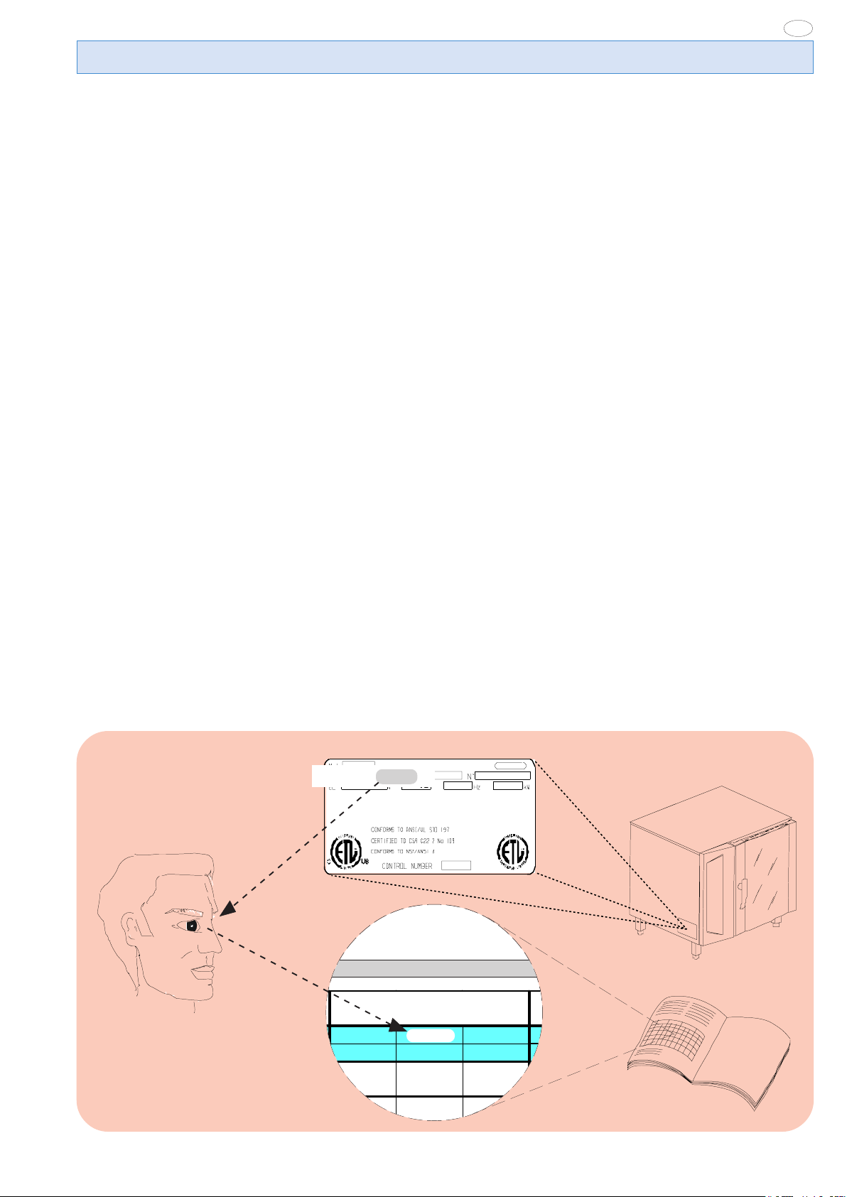
- APPLIANCE IDENTIFICATION
- CONTROL PANEL FIGURES ......................................... 107
Rating plate
PNC 9PDX 260462 05
260462
5958 992 00
11
Page 12

EN
I. GENERAL CHARACTERISTICS
1. APPLIANCE DESCRIPTION
This handbook concerns various appliance models.
For further information regarding your model, refer to Table
1"Technical Data”.
The appliance has the following features:
• Digital indication of temperature.
• Thermostatic probe for measuring the product’s “core” temperature (core probe).
• Constant monitoring of cooking parameters during the entire
cycle.
• Periodical emptying and subsequent automatic washing of the
steam generator to prevent excess scaling.
• Signalling the need for periodical boiler maintenance, see relevant section.
2. TABLE 1: TECHNICAL DATA
• Compartment rapid fume extraction device for gratinating, with
automatic activation.
• AIR-BREAK anti-backflow device for preventing backflow from
the drainage system entering the oven.
• Compartment lighting lamps.
• Door opening double-action safety mechanism to prevent burns.
• Door with double glass: better comfort in the kitchen and low
surface temperatures.
• Cycle for daily cleaning of cooking compartment (CLEANING
SYSTEM) (according to model).
• Self-diagnosis for possible malfunctions by means of signalling
with identification codes (refer to par. “Information and error
codes”.
GRI DS
PNC *
CONVECTO R °
BOILER * *
SUPPLY VOLTAGE
Total W atts
Maximum load capacities
(food)
Net we ight
Shipping we ight
Shipping width
Shipping height
Shipping depth
10GN1/1
(AOW101E)
260573
°
**
208V 3ph
60Hz
64amps
23 kW
110 lbs.
(50 kg)
386 lbs
(175 kg)
430 lbs.
(195 kg)
42 15/16"inch
(1090 mm )
49 5/8"inc h
(1260 mm )
39 9/16"inc h
(1005 mm)
Information on sound emissions: The functional components
of the appliances in question have a noise level not exceeding 70
dB (A).
The model of your oven is indicated at the PNC field on the
*
“Technical Data” plate located at the bottom of the left side.
^ OPERATING LEVEL.
5958 992 00
12
Page 13

EN
3. GENERAL INSTRUCTIONS
• The following terms alert you to potentially dangerous conditions
to the operator, service personnel or to the equipment.
• Danger! This term warns of immediate hazards which will result in
severe injury or death.
• Warning! This term refers to a potential hazard or unsafe
practice which could result in injury or death.
• Notice. This term refers to information that needs special
attention or must be fully understood, even though not dangerous.
• Keep the appliance area free and clear from combustibles.
Warning Fire hazard.
For your safety, do not store or use gasoline or other flammable,
vapors and liquids in the vicinity of this or any other appliance.
Keep area around appliances free and clear of combustibles
Warning!
Failure to properly vent the oven can be hazardous to the health
of the operator; and will result in operational problems,
unsatisfactory baking, and possible damage to the equipment.
Damage sustained as a direct result of improper ventilation will
not be covered by the Manufacturer’s warranty.
WARNING: The equipment warranty is not valid unless the
appliance is installed, started and demonstrated under the supervision
of a factory trained installer.
WARNING: The unit must be installed by Personnel who are
qualified to work with electricity and plumbing. Improper installation
can cause injury to personnel and/or damage to the equipment. The
unit must be installed in accordance with applicable codes.
Important: The installation instructions contained
herein are for the use of qualified installation and
service personnel only. Installation or service by
other than qualified personnel may result in
damage to the appliance and/or injury to the
operator. FAILURE TO COMPLY WITH
INSTALLATION INSTRUCTION OR
IMPROPER INSTALLATION WILL VOID
WARRANTY AND RESPONSIBLITIES OF THE
MANUFACTURE.
NOTICE: INTENDED FOR COMMERCIAL USE ONLY. NOT
FOR HOUSEHOLD USE.
CAUTION HOT SURFACES
CAUTION RISK ELECTRIC SHOCK
CAUTION: Do not locate unit adjacent to any high heat or
grease producing piece of equipment, such as a range top,
griddle, fryer, etc., that could allow radiant heat to raise the
exterior temperature of the Air-O-Steam Oven.
• Before installing and starting the appliance carefully read this
handbook as it provides important information and instructions
on safety, installation, use and maintenance.
• Our appliances have been studied and optimized to give the
highest performance. This appliance is intended for industrial use
only and is specifically designed to cook food. Any other use will be
considered “improper use” and will void the warranty and
manufacturer liability.
WARNING: ANY POTENTIAL USER OF THE EQUIPMENT
SHOULD BE TRAINED IN SAFE AND CORRECT OPERATIONG
PROCEDURES.
WARNING: BEFORE SERVICING, DISCONNET THE
ELECTRICAL SERVICE AND PLACE A RED TAG AT THE
DISCONNECT SWITCH TO INDICATED WORK IS BEING DONE
ON THAT CIRCUIT.
NOTICE: Using any parts other than OEM original spare parts
relieves the manufacturer of all warranty and liability.
• Carefully keep this handbook for further consultation by the
various operators, or in case the appliance is resold.
• The installation of this unit must conform to local codes or, in the
absence of local codes, to all National Codes governing plumbing,
sanitation, safety and good trade practices.
5958 992 00
NOTICE: Manufacturer reserves the right to change specifications
at any time without notice.
Failure to comply with the above requirement may jeopardise
the safety of the appliance and invalidate the guarantee.
13
Page 14

EN
WARNING: DO NOT SPRAY THE OUTSIDE OF THE
APPLIANCE WITH WATER OR CLEAN WITH A WATER JET.
CLEANING WITH A WATER JET CAN IMPREGNAT
CHLORIDES INTO THE STAINLESS STEEL, CAUSING THE
ONSET OF CORROSION.
WARNING: DO NOT USE PRODUCTS CONTAINING
CHLORINE (BLEACH, HYDROCHLORIC ACID ETC.) EVEN
DILUTED, TO CLEAN STEEL SURFACES.
WARNING: DO NOT USE CORROSIVE SUBSTANCES (E.G.
MURIATIC ACID) TO CLEAN THE FLOOR UNDER THE
APPLIANCE.
4. THE ENVIRONMENT
4.1 PACKING
• All packing materials are environmentally friendly. They can be
stored without risk or burned in a special waste incineration plant.
Recyclable plastic components are marked as follows:
polyethylene : outer wrapping, instruction handbook
PE bag, gas nozzle bag.
polypropylene: roof packing panels, straps
pp
polystyrene foam: corner protectors
PS
4.2 USE
• Our appliances are designed and optimized with laboratory testing in order to offer high performance and efficiency. In any case,
to reduce energy consumption (electricity, gas and water), avoid
using the equipment empty for long periods or in conditions that
compromise optimum efficiency (e.g. door open). Also, if possible, pre-heat the appliance immediately before use.
4.3 CLEANING
• In order to reduce the emission of pollutants into the environment, it is advisable to clean the appliance (externally and when
necessary internally) with products that are more than 90% bio-
degradable %.
4.4 DISPOSAL
• At the end of the appliance’s working life, make sure it is not
dispersed in the environment.
• Our appliances are manufactured using more than 90% metal
materials (stainless steel, iron, aluminum, galvanized sheet, etc.)
which can therefore be recycled by means of the conventional
recovery facilities, in conformity with the current regulations in
the country of use.
• Make the appliance unusable by removing the power cable and
any compartment or cavity closing mechanisms (when present)
in order to avoid the risk of someone becoming closed inside.
14
5958 992 00
Page 15

II. INSTALLATION INSTRUCTIONS
Important: The external panels of the oven must be
removed for the operations described in this section. As the
unit must be operating in order to carry out some
adjustments, pay maximum attention to the live parts.
1.3 UNPACKAGING
• Remove the appliance from the packaging and take away the
protective film that covers the appliance's external panels carefully to avoid leaving any trace of glue. If necessary remove the glue
using an a non-corrosive solvent, rinsing it off and drying carefully.
• Dispose of packaging material in compliance with the regulations
in force in the country where the product is to be used.
EN
1. PLACE OF INSTALLATION
1.1 VENTILATION
The necessity for a properly designed and installed ventilation
system cannot be over emphasized. The ventilation system will
allow the unit to function properly while removing unwanted vapors
and products of combustion from the operating area.
The appliance must be vented with a properly designed mechanically
driven exhaust hood. The hood should be sized to completely cover
the equipment plus an overhang of a least 6"/15.3cm on all sides not
adjacent to a wall. The capacity of the should be sized appropriately
and provisions for adequate makeup air.
Refer to your local ventilation codes. In the absence of local codes,
refer to the National ventilation code titled, “Standard for the
Installation of Equipment for the Removal of Smoke and Grease
Laden Vapors from Commercial Cooking Equipment”, NFPA-96Latest Edition.
It is recommended that the ventilation system and duct work be
checked at prevailing intervals as specified by the hood manufactured
• The appliance must only be installed in adequately ventilated
premises.
NOTICE: Proper ventilation is the owner's is responsibility. Any
problem due to improper ventilation will not be covered by the
warranty.
1.2 REFERENCE STANDARDS
Note: The electric supply installation must satisfy the requirements
of the appropriate statutory authority, such as the National Electrical
Code (NEC) ANSI/NFPA70, (U.S.A..): the Canadian Electrical
Code, CSA C22.2; or other applicable regulations.
Note: The electric supply connection must meet all national and
local electrical code requirements.
Note: The installation of this unit must conform to local codes or,
in the absence of local codes, to all National Codes governing
plumbing, sanitation, safety and good trade practices, and to the
National Gas Code ANSI Z223.1.
• Local codes regarding installation vary greatle from one area to
another. This equipment is to be installed to comply with the
applicable federal, state or local codes.
The installation instructions contained herein are for the use of
qualified installation and service personnel only. Installation or
service by other than qualified personnel may result in damage to
the appliance and/or injury to the operator.
FAILURE TO COMPLY WITH INSTALLATION INSTRUCTION
OR IMPROPER INSTALLATION WILL VOID WARRANTY AND
RESPONSIBLITIES OF THE MANUFACTURE.
The National Fire Protection Association, Inc states in its NFPA 96
latest edition that local codes are the "authority having jurisdiction"
when it comes to installation requirements for equipment.
Therefore, installations should comply with all local codes.
5958 992 00
1.4 IMMEDIATELY INSPECT FOR SHIPPING DAMAGE
The container should be examined for damage before and during
unloading. The freight carrier has assumed responsibility for its
safe transit and delivery. If damaged equipment is received,
either apparent or concealed, a claim must be made with the
delivering carrier. Apparent damage or loss must be noted on the
freight bill at the time of delivery. The freight bill must then be
signed by the carrier representative (Driver). If the bill is not
signed, the carrier may refuse the claim. The supply can supply
the necessary forms. A request for inspection must be made to
the carrier within 15 days if there is concealed damage or loss that
is not apparent until after the equipment is uncrated. The carrier
should arrange an inspection. Be certain to hold all contents plus
all packing material. Under no circumstances should a damaged
appliance be returned to the manufacturer without prior notice and
written authorization.
2. POSITIONING
• For the overall space required and connection dimensions, refer to the installation diagrams given on the first pages of this
instruction handbook.
• The left, right and top surface of the appliance must remain
at least 23.62" (50cm) from other surfaces to enable maintenance
interventions (if not possible, minimum 1.97" -5cm- is request for
left and right), whereas the back must be at least
1.97" (5cm) from any surface.
• Position the appliance and if necessary adjust the height of the
worktop by means of the adjustable feet.
• The appliance is not suitable for built-in installation.
Important:
Make sure the steam coming from the oven discharge or
adjacent appliances does not reach the special vents for
the cooling of internal components, located at the
bottom of the appliance.
3. ELECTRICAL CONNECTION
• A fused disconnect switch or main circuit breaker (customer
furnished) MUST be installed in the electric supply line for the
appliance. It is recommended that this switch/circuit breaker
have lockout/tagout capability. Before making any electrical
connections to this appliance, check that the power supply is
adequate for the voltage, amperage, and phase requirements
on the rating plate.
• A safety cutout switch of suitable capacity with a contact
breaking distance of at least 3 mm must be fitted upstream of the
appliance.
The cutout switch must be installed near the appliance in the
permanent electrical system of the premises.
15
Page 16

EN
• The appliance must be electrically grounded in accordance with
local codes, or in the absence of local codes, with the National
Electrical Code, ANSI/NFPA 70, or the Canadian Electrical
Code, CSA C22.2, as applicable.
The grounding conductor must therefore be connected to the
terminal marked Gon the connection terminal board. The
appliance must also be connected to an earth grounding
system.
This connection is made using the stop screw marked E
located on the outside of the appliance near the power cable
inlet.
The grounding wire must have a minimum cross-section of
8 AWG (10 mm
GROUNDING INSTRUCTIONS
This appliance must be connected to a grounded, metallic,
permanent wiring system, or an equipment grounding
conductor should be run with the circuit conductors and
connected to the equipment grounding terminal or lead on
the appliance.
2
).
RATING PLATE
::
:
::
3.1 POWER CABLE INSTALLATION
To connect the power cable to the appliance, proceed as follows:
Model 6 - 10 - 20 GN
• Remove the left side panel.
• Connect the cable to the terminal block as shown in the wiring
diagram attached to the appliance, and secure it with the special
cable gland.
The manufacturer declines any liability if the safety regulations are not respected.
The manufacturer requires when stacking units each appliance
have its own branch circuit protection. An air-o-speed® unit stacked
with an air-o-chill® unit should have a separate circuit breaker for the
upper and lower units.
4.1 SUPPLY WATER CHARACTERISTICS
4.1.1 WATER INLET “N”.
Important (LEVEL A ONLY)
The water supply pipe must have an inside diameter of at
least 20 mm and be free of elbow unions.
The discharge steam condensation system can be fed with cold
water suitable for human consumption, having the following
characteristics:
- total hardness not exceeding 400ppm (40°fH); in LEVEL
A ovens equipped with CLEANING SYSTEM it is advisable to use
water of hardness not exceeding 5° French; for that purpose, a
water softener with automatic regeneration for installing on inlet
line “N” is supplied as an accessory by request.
- pressure between 22 to 36 psi (150-250 kPa); higher
pressures involve waste of water.
Note:
To check correct water installation, make sure the rotating wash
arm (CLEANING SYSTEM) does not turn below 100 rpm (120
max).
4.1.2 WATER INLET “B”.
(With feed pipe supplied)
The inlet for steam production must be fed with water suitable
for human consumption, having specific characteristics:
- total hardness between 5 - 50ppm (0.5 - 5 °fH) French
for reducing scaling inside the steam generator.
For that purpose, a water softener with automatic regeneration
for installing on inlet line “B” is supplied as an accessory by request;
it has a kit for sterilizing the resins (by further request).
- pressure between 22 to 36 psi (150-250 kPa); higher
pressures involve waste of water.
- chlorine concentration (Cl -) not high (acceptable refer-
ence value ~10 ppm), so as not to damage the steel structures
inside the oven.
- pH higher than 7.
For that purpose, a special filtering unit for installing on inlet line
“B” is supplied as an accessory by request. The purpose of this
unit is to reduce the water hardness to optimum values (below
50ppm "5 °fH") (optimum value), and therefore also serving as a
water softener.
- electric conductivity between 50 and 2000 µS/cm (68°F)
(20°C).
4. WATER CONNECTION
(See the installation diagrams at the beginning of this handbook)
This equipment is to be installed to comply with the applicable
Federal, State, Local plumbing codes, or the Basic Plumbing
Code of the Building Officials and Code Administrators
International Inc. (BOCA) and Food Service Sanitation Manual
of the Food and Drug Administration (FDA).
The oven has two separate inlets (“B” and “N”) for the supply
water.
The supply pipes of both inlets must be equipped with a mechanical filter and shutoff cock. Before installing the filters, it is
advisable to let a certain amount of water flow in order to clean
the pipe of any solid particles.
Important: The use of water treatment systems utilizing
methods different from those indicated by the manufacturer of
the equipment is not allowed and will completely invalidate the
warranty.
Likewise, dispensers of substances for preventing scale in
the pipes (e.g. polyphosphate dispensers) must not be
used because they can compromise correct machine
operation.
4.2 WATER DRAINING SYSTEM
The oven has an AIR-BREAK anti-backflow device inside to prevent possible backflow from the drainage system entering the
internal pipes and the oven compartment. This allows the drain
pipe to be connected directly to the mains system or discharging
into a floor grate.
The drain pipe (rigid or flexible type) can be run to the side or
16
5958 992 00
Page 17

back if the oven is not placed against a wall, excluding the front
part with rack support structure. It must not be more than 3 feet
(1 metre) long, with inside diameter not less than that of the
oven discharge pipe (1" 1/4), and must withstand temperatures
of at least 212°F (100°C). Make sure there are no constrictions in
hoses or elbows in metal pipes, along the entire drain path. Avoid
horizontal sections where water can collect and stagnate (min.
slope 5%).
WARING: BLOCKING THE DRAIN IS HAZARDOUS.
C - Oven drain
C1 - Safety outlet
Important:
- Do not obstruct the safety outlet C1.
- Do not connect the safety outlet C1 to the drainage system.
Note:
If water comes out of the AIR-BREAK (safety outlet C1) this means
the drain C is blocked. Any elimination of the obstruction must
be carried out by specialized technical personnel.
5. SAFETY DEVICE
The appliance is equipped with the following safety devices:
- Fuses, see the wiring diagram, located behind the control panel.
For replacement, unscrew the holding cap and replace the damaged component with another one of equal capacity; this value is
indicated on the rating plate located in the same place.
- Compartment manual-reset safety thermostat located behind the control panel; it intervenes, cutting off the convection
heating supply.
RESETTING OPERATIONS MUST BE CARRIED OUT BY
SPECIALIZED TECHNICAL PERSONNEL AFTER ELIMINATING
THE CAUSES OF INTERRUPTION.
- Automatic-reset thermal device inside the fan motor, which
intervenes in case the motor overheats, protecting equipment
operation; it intervenes, cutting off the electric power to the appliance.
- MAGNETRON manual-reset safety thermostat located behind the left side panel; it intervenes, cutting off the power supply
to the MAGNETRON.
Resetting operations must be carried out by specialized technical personnel after eliminating the causes of interruption.
5958 992 00
EN
6. OPERATION CHECK
- Switch the appliance on, following the instructions in the section “Operating instructions”;
- Explain appliance operation, routine maintenance and cleaning
operations to the user, with the help of the instruction handbook.
Important:
- During operation, pay attention
to the hot zones of the exterior surface.
- Do not place objects on the outlets located at the top
of the appliance.
- With oven hot, check the correct working of the door closing
mechanism. If necessary, adjust closing by adjusting the position
of the catch.
7. MAINTENANCE
PRECAUTION TO BE OBSERVED BEFORE
AND DURING SERVICING TO AVOID POSSIBLE
EXPOSURE TO EXCESSIVE MICROWAVE ENERGY
(a) Do not operate or allow the oven to be operated with
the door open.
(b) Make the following safety checks on all ovens to be
serviced before activating the magnetron or other
microwave source, and make repairs as necessary:
(1) interlock operation,
(2) proper door closing,
(3) seal and sealing surfaces (arcing, wear, and other
damage),
(4) damage to or loosening of hinges and latches,
(5) evidence of dropping or abuse.
(c) Before turning on microwave power for any service
test or inspection within the microwave generating
compartments, check the magnetron, wave guide or
transmission line, and cavity for proper alignment,
integrity, and connection.
(d) Any defective or misadjusted components in the
interlock, monitor, door seal, and microwave generation
and transmission systems shall be repaired, replaced, or
adjusted by procedures described in this manual before
the oven is released to the owner.
(e) A microwave leakage check to verify compliance with
the Federal Performance Standard should be performed
on each oven prior to release to the owner.
The components requiring routine maintenance are accessible
by opening the control panel, and the left, right and rear panels.
Danger: Live voltage is present with panels removed and unit
switch on. Exercise extreme caution when work with live voltage.
NOTICE: Using any parts other than OEM original spare parts
relieves the manufacturer of all warranty and liability.
::
:
::
17
Page 18

EN
8. BRIEF TROUBLESHOOTING GUIDE
Even with correct use, malfunctions can occur.
Oven compartment heating does not switch on or is inefficient. Possible causes:
- Oven compartment temperature limiter activated
- Heating elements damaged
- Element contactor coil damaged
- Oven compartment temperature probe damaged (error EPt1 con-
figuration).
- Controller damaged
- Fuse F2 blown, see wiring diagram.
- MAGNETRON limiters activated.
The steam generator heating does not switch on or is inefficient in steam production. Possible causes:
- Heating elements damaged
- Element contactor coil damaged
- Controller damaged
- Fuse F2 blown
- No water in system
- Boiler drain closing device faulty
- Water inlet solenoid valves damaged (they do not open)
Incorrect oven compartment temperature thermostatting.
Possible causes:
- Electronic controller faulty.
- Oven compartment temperature probe dirty, faulty or discon-
nected, see error EPt1 configuration.
The oven goes off. Possible causes:
- Fuse F2 blown due to damaged auxiliary circuit components.
Oven compartment lamps damaged
Important: Switch the appliance off before changing oven com-
partment lamps.
9. POSITIONING OF MAIN COMPONENTS
(Any operation inside the appliance must only be carried out
by an installer authorized by the Manufacturer)
Open the control panel to access the following components:
Danger: Live voltage is present with panels removed and unit
switch on. Exercise extreme caution when work with live voltage.
- Electronic boards.
- Compartment temperature limiter thermostat.
- Fuses.
- Door safety microswitch.
- Transformer for compartment lamps
- Compartment vent shutter control gear motor
WARNING: Before servicing unit switch off power at the main
circuit breaker and place a red tag on the breaker to indicate work
is being done on the circuit.
Remove the appliance left, right and rear panels to access to all
the other components.
18
5958 992 00
Page 19

III. OPERATING INSTRUCTIONS
EN
Before starting the appliance, carefully read this handbook. The
instructions and information given in it are important for correct
and optimum oven use. If required, further details regarding its
characteristics and cooking performance can be obtained from
the dealer.
ANY POTENTIAL USER OF THE EQUIPMENT SHOULD BE
TRAINED IN SAFE AND CORRECT OPERATING PROCEDURES.
• This appliance is intended for industrial use only and is specifically
designed to cook food. Any other use will be considered "improper
use" and will void the warranty and manufacturer liability.
• To avoid obstructing the fume and steam discharge pipes, do
not place pans or utensils of any kind on the oven.
• Have the appliance fully checked periodically (at least once a
year). For that purpose, it is advisable to stipulate a maintenance
contract.
• The core probe is a precision component. Absolutely avoid
impacts, forcing when inserting, and pulling of the flexible cable (in
particular when using the trolley-mounted structures). The
warranty does not cover the replacement of core probes
damaged by improper use.
• In the combi cooking cycle it is advisable not to exceed
temperatures of 392-410°F (200-210°C). Higher values can reduce the efficiency of the compartment seals.
• When arranging food inside the oven compartment, keep a
space of at least 1.5" (40 mm) between trays, to ensure better
circulation of hot air.
• Do not salt food inside the oven compartment, in particular
with humid cycles.
MICROWAVE INSTRUCTIONS
- make sure the utensils are those suitable for microwave
ovens;
- when warming food in paper or plastic containers, check the
oven frequently, due to the risk of fires;
- if any smoke is noticed, switch off and unplug the appliance
and keep the door closed in order to extinguish possible
flames;
- eggs with shells and hard boiled eggs must not be warmed
in microwave ovens because they may explode.
- periodically clean the oven, removing all traces of food;
failure to keep the oven clean will lead to deterioration of the
surfaces, and thus affect appliance life and give rise to
hazardous situations.
- IMPORTANT - IF THE DOOR OR THE DOOR SEALS ARE
DAMAGED, THE OVEN MUST NOT BE USED UNTIL IT HAS
BEEN REPAIRED BY AUTHORIZED PERSONNEL;
- WARNING - IT IS DANGEROUS FOR ANYONE EXCEPT
AUTHORIZED PERSONNEL TO CARRY OUT MAINTENANCE
OR REPAIR OPERATIONS INVOLVING THE REMOVAL OF
ANY COVER PROTECTING AGAINST EXPOSURE TO MICROWAVE ENERGY;
Only use the HEAT PROBE (probe) recommended for this
microwave oven.
• Do not place flammable liquids (e.g. spirits) inside the oven
compartment during operation.
Important!
The maximum height at which the trays are placed in the oven
does not exceed 5.25 ft (tm. 1,6). This applies if it is installed
according to the instructions and with the use of original
accessories.
Whenever using supports different from ours, make sure not to
exceed the above-mentioned height when installing the oven.
Otherwise there could be the risk of spilling hot cooking liquids
(sauces, oil, melted fat, etc.) contained in the high trays and
not visible during handling.
PLACE THE LABEL SUPPLIED AND CONTAINING THE FOLLOWING INSTRUCTIONS, IN A VISIBLE POSITION NEXT TO
THE OVEN:
- CAUTION - MICROWAVE WARMING OF BEVERAGES
MAY RESULT IN DELAYED BOILING OVER, THEREFORE
TAKE CARE WHEN HANDLING THE CONTAINER;
- CAUTION - FEEDING-BOTTLES AND HOMOGENIZED
FOODS IN JARS MUST BE OPEN DURING WARMING, THE
CONTENTS MUST BE AGITATED OR SHAKEN AND THE
TEMPERATURE MUST BE CHECKED BEFORE CONSUMPTION, IN ORDER TO AVOID SCALDING;
- CAUTION - LIQUIDS OR OTHER FOODS MUST NOT BE
WARMED IN SEALED CONTAINERS BECAUSE THEY
COULD EXPLODE.
PRECAUTIONS TO AVOID POSSIBLE
EXPOSURE TO EXCESSIVE MICROWAVE ENERGY :
(a) Do not attempt to operate this oven with the door open
since open-door operation can result in harmful exposure
to microwave energy. It is important not to defeat or
tamper with the safety interlocks.
(b) Do not place any object between the oven front face
and the door or allow soil or cleaner residue to
accumulate on sealing surfaces.
(c) Do not operate the oven if it is damaged. It is
particularly important that the oven door close properly
and that there is no damage to the:
(1) door (bent),
(2) hinges and latches (broken or loosened),
(3) door seals and sealing surfaces.
(d) The oven should not be adjusted or repaired by
anyone except properly qualified service personnel.
5958 992 00
19
Page 20

EN
1. OVEN DOOR OPENING
The oven is equipped with a safety system to prevent you being
exposed to steam when opening the door completely, therefore
carry out the following operations, according to the model:
1.1 6- AND 10-RACK MODELS
Caution! Risk of burns.
Always open the door with caution when the oven is hot.
a) Turn the oven door handle counter-clockwise as far as it will go.
The door opens slightly and is stopped by the door safety device.
If there is a cooking program in progress it will be interrupted but
will continue when door is closed.
3. DESCRIPTION OF CONTROL PANEL
3.1 FOREWORD
For easy understanding of oven operation, when reading keep
the flap relating to the control panel of your model open, identifying it from those given on the last pages of this manual.
All the functions available in the various models of the range are
described below.
Certain functions are shared by all models, whereas others
are available only on some versions.
3.2 BASIC CONTROLS
Main switch
Cooking cycle/program Start/stop.
b) Turn the door handle to the vertical position and then pull
outwards, the door will offer light resistance and then open
completely.
2. OVEN DOOR CLOSING
2.1 6- AND 10-RACK MODELS
a) Turn the door handle counter-clockwise as far as it will go and
press the door closed against the oven.
b) Keeping the door pressed closed, lock it by turning the handle
to the vertical position.
GRAPHIC DISPLAY management controls : buttons for selecting oven control mode.
GRAPHIC DISPLAY
Graphic display for showing all available oven functions.
P1-P2-P3-P4 Button for selecting the functions shown on the
GRAPHIC DISPLAY.
Press this button once to select the function shown above the
arrow.
K Knob for selecting and setting the values of each function.
20
5958 992 00
Page 21

EN
3.3 MAIN COOKING MODES
Convection cycle: for roasting and gratinating at maximum tem-
perature 572°F(300°C).
Combi cycle: superheated steam. The steam generator and compartment heaters are used at the same time to keep foods soft
(max. temperature 482°F)(250°C).
Steam cycle: Ideal for boiling (operating temperature automatically fixed at 212°F)(100°C).
Low temperature steam can be set for gentle cooking, vacuum
packed foods and for thawing (temperature from 77°F a
210°F)(25° to 99°C); superheated steam 214° a 266)(101° a
130°C).
Microwave cycle: fast heating by microwaves that act directly
inside the food.
1:00
Timer for control of cooking time.
Digital thermometer/thermostat for control of product core tem-
perature.
- Microwave adjustment: for adjusting microwave power in all
cooking cycles.
1:00
3.4 SPECIAL COOKING MODES
Utilities
Functions useful for the type of cooking required.
Low power cycle (heating): for gentle baking, such as light patisserie. Combinable with all cycles.
Regeneration cycle: produces the optimum humidity for fast
heating of products to be regenerated (max. temperature
482°F)(250°C).
The regeneration program is a single phase function characterized by:
- a special cycle with controlled humidity;
- a preset temperature of 356°F(140°C) (adjustable if required);
- use of full power;
- operation in continuous Cont mode; once activated it remains
on with the door open or closed.
Caution
Always
Alternatively to continuous mode it can also accept a set cooking
time or the core probe.
Pause phase: by setting a time in this mode, it is possible to
delay the start of cooking programs or include pauses between
two cycles (e.g. proving).
- Electronic humidity adjustment: enables adjustment of the
required humidity level in convection, combi and regeneration
cycles.
! Risk of burns.
open the door with caution when the oven is hot.
300
Digital thermometer/thermostat for control of compartment tem-
5958 992 00
perature.
Low speed cycle (fan): for gentle baking, such as light patisserie. Combinable with all cycles.
Convection and microwave cycle with compartment vent
open: for very dry cooking, allowing the removal of humidity when
necessary (max. temperature 572°F (300°C).
Maintaining cycle (149°F) (65°C): for slow and prolonged
cooking, typically for meat (large cuts). Activated at the end of
cooking.
It can be used in combination with convection and steam modes.
Cooking with ECO-DELTA: for cooking large pieces of food (5kg
and over, e.g. whole turkey, leg of pork, etc.).
A temperature setting of between 34°F(1°C) and 248°F(120°C)
is used in this cooking mode.
In this case, cooking is moderate and long, because the COMPARTMENT temperature is automatically adjusted according to
that inside the food (CORE PROBE), maintaining a constant difference (ECO-DELTA) between them, throughout cooking.
E.g.
COOKING: START ...... END
ECO-DELTA = 176°... 176... 176... 176... 176°F (set)
CORE PROBE = 50°... 51... 52... 104... 140°F (set)
COMPARTMENT = 194°... 195... 196... 248... 284°F (result)
21
Page 22

EN
3.5 ADDITIONAL FUNCTIONS
Preheat or cooking: indicates (in AUTOMATIC) that the oven is
preheating the compartment (please wait) or cooking.
Warning light signalling oven door open.
Scale light: when this light comes on, the steam generator must
be descaled. Follow the instructions given in par. 7.
Introduce food (and insert core probe): indicates (in AUTOMATIC) that the oven is ready for loading food and possibly for
inserting the core probe in the product to be cooked.
Higher core temperature?: enables the core probe temperature to be increased at end of cycle (in AUTOMATIC).
More time?: enables the cooking time to be increased at end of
cycle (in AUTOMATIC).
Cooking with phases in sequence: for setting cooking programs
with several phases in automatic sequence (max. 6 phases).
- MANUAL -
Skip PHASE: for going from the phase in progress to the next.
- AUTOMATIC -
Display from AUTOMATIC to MANUAL: enables (in Manual
mode) control of the corresponding cooking parameters set in
Automatic mode.
D
DELAY START - (delayed cycle start): enables the cooking
cycle to be started later, by setting the required time.
A B C
Steam generator status light:
A - generator in filling phase or no water. Make sure water
reaches the oven!
B - generator in preheating phase.
C - generator ready (light off).
Information: press this button for important help regarding the
functions, and instructions on how to proceed.
Manual injection of water in compartment: for instantly increasing the moisture level during a cooking cycle.
Manual draining of steam generator water: press the button to
drain water from the steam generator.
Important
generator, make sure to:
respect the parameters regarding the water supply – see
always drain the generator at the end of each day.
! In order to reduce excessive scaling in the steam
installation;
Maintenance (Service)
A number of functions necessary for oven maintenance.
Display of current cooking parameters: press the corresponding
button to check the compartment temperature and humidity
values, the core probe temperature and cycle duration at any time
during cooking.
Cleaning System: automatic oven cleaning cycle (refer to par. 7.
CLEANING AND MAINTENANCE).
Fast compartment cooling: useful for going from one type of
cooking to another at lower temperature; it enables fan rotation
and automatic injection of water (TS < 180°C) even with the door
open.
Caution
Always
Before using the oven, make sure:
- the external electric safety switch is on;
- the water shutoff cocks are open;
- the oven outlets are not blocked.
22
! Risk of burns.
open the door with caution when the oven is hot.
5958 992 00
Page 23

OVEN USE
4. OPERATING LEVEL A
Foreword:
The initial condition is restored if no key is pressed or the knob is
not turned within 15 seconds (approx.) when selecting some functions.
4.1 SWITCHING THE OVEN ON
To switch the oven on, press the button I(O - I) of the following
switch:
EN
4.3 AUTOMATIC (Automatic control)
The AUTOMATIC control mode is used for automatic cooking, by
setting several simplified functions. This saves the operator from
having to know the cooking parameter values (temperature, time,
humidity and microwave) and makes the same type of cooking
more equal.
The functions to be set are as follows:
1) FOOD category
- 2) FOOD type
- 3) FOOD load
- 4) FOOD status
- 5) FOOD cooking level
4.3.1 FOOD CATEGORY
1) Press the button P2 (
turning knob K.
) and select the food CATEGORY by
The following occurs:
- the corresponding button lights up;
- the control panel lights up and the page in manual is shown;
- the display indicates the parameters (convection cycle, tem-
perature, and time) already set on the oven;
- the compartment lights up;
- the steam generator is
in filling phase
or no water
Make sure water reaches the oven!
- the steam generator is
in preheating phase ;
- the steam generator is
ready
(light off);
4.1.1 SWITCHING THE OVEN OFF
The oven is switched off by pressing the button O (O - I) of the
following switch:
PORK
FILLET
MED
12PCS 25oz 3GRID
FRESH
PORKPORK
PORK
PORKPORK
PORK is selected in the figure
2) Press the button P2 ( ) and select the food type with knob K.
4.2 SELECTING CONTROLS
(AUTOMATIC, MANUAL OR PROGRAMMED)
After SWITCHING THE OVEN ON select one of the following 3
modes to control the oven by pressing the relative button:
AUTOMATIC = automatic (
MANUAL = manual (
PROGRAM = programmed (
)
)
)
5958 992 00
FILLET
MED 12PCS 25oz 3GRID
FRESH
P2
3) Press the button P2 (
) and select the food load (MIN - MED -
MAX) with knob K (e.g. 3 grids with 12 pieces 25 oz "700 g" to one)
.
FILLET
MED 12PC 700G 3RACKS
FRESH
23
Page 24

EN
4) Press the button P2 ( ) and select the food status (FRESH -
FROZEN) with knob K.
MED 12PCS 25oz 3GRID
FRESH
This field is not selectable for some food types because there is only
one food condition, only FRESH or only FROZEN.
5) Press the button P2 (
) and select the food cooking level with
knob K .
FRESHFRESH
FRESH
FRESHFRESH
level 3 of 5
__
___________
FRESH
The GRAPHIC DISPLAY shows the COOKING IN PROGRESS
screen, giving the following information:
condition* __________________
PREHEATING
Time elapsed_______________
0:08
_____
Food CATEGORY
Food TYPE
Food LOAD
Food STATUS
_____________________
_________________
_________________
COOKING LEVEL
_______
PORK
FILLET
MED 12PC 700g 3RACKS
FRESH
_________________
P2 P4
P1 P2
6) If necessary, press the button P1 ( ) to go to the previous
functions.
Note:
In MANUAL mode, to check the corresponding parameters set in
AUTOMATIC MODE, press the following button
from AUTOMATIC to the corresponding MANUAL
After entering MANUAL mode it is not possible to go back to the
AUTOMATIC mode settings, therefore a new setting must be made,
whereas it is possible to modify the corresponding set parameters
and start cooking.
* The operating condition during cooking can be one of the following:
PREHEATING (please wait)
INTRODUCE FOOD or
INTRODUCE FOOD and CORE PROBE
- Open the door and introduce the product to be cooked
Caution! Risk of burns.
Always open the door with caution when the oven is hot.
- Close the door and press the button P4 ( )to confirm that
the food and the core probe have been introduced.
COOKING
HIGHER TEMPERATURE AT CORE ?
Turn the knob K to increase the cooking temperature at the
core of the food.
Press the button P2 (
EXTRA TEMPERATURE AT CORE?
) to confirm or P3 ( ) to cancel.
65
4.3.2 STARTING COOKING CYCLE - AUTOMATIC
- make sure the oven door is closed;
- Press the START/STOP button (the message PREHEAT appears)
Preheating is automatic for any set cooking cycle and cannot be
skipped in the AUTOMATIC control.
PORK
MORE TIME ?
Turn the knob K to increase the cooking time.
Press the button P2 ( ) to confirm or P3 ( ) to cancel.
EXTRA TIME?
0:10
PORK
5958 992 00
24
Page 25

EN
Note:
- The cooking cycles (steam, combi, convection and regenera-
tion) cannot be started until the steam generator is ready, as indicated by the corresponding light off (see par. 4.1).
During this period the time count does not start and the Start
cooking button flashes; this occurs also when the oven door is
opened.
Caution! Risk of burns.
Always open the door with caution when the oven is hot.
4.3.3 STOPPING THE COOKING CYCLE - AUTOMATIC
At the end of the set time, the cooking cycle automatically stops
and the oven bell sounds continuously.
Open the door and remove the product.
Caution! Risk of burns.
Always open the door with caution when the oven is hot.
Notes:
- The bell can be stopped in advance by carrying out any opera-
tion on the control panel or by opening the door.
The cooking cycle can be stopped manually by keeping the cycle
Start/Stop button pressed for 2 seconds.
Shorter presses will be ignored by the oven.
A cycle identical to that just completed can be repeated by pressing the Start/Stop button again.
1:00'
4.4 MANUAL (Manual control)
SETTING COOKING CYCLE
The MANUAL control mode is used to carry out food cooking
manually by setting the various parameters of a cycle.
The food is cooked by heating it and can occur in a certain MODE,
with a givenTEMPERATURE, TIME and also HUMIDITY. Therefore these factors must be set in order to perform a COOKING
CYCLE.
The oven works mainly by carrying out the operations given in
the following sections:
— SETTING COOKING CYCLE —-
- SELECTING COOKING MODE
- SETTING COOKING TEMPERATURE
- SETTING COOKING TIME
- SETTING AND USE OF CORE PROBE
- SETTING COOKING HUMIDITY
- MICROWAVE SETTING
- STARTING THE COOKING CYCLE
There are also other sections containing instructions on support
functions, such as:
- MANUAL CYCLE (CONTINUOUS COOKING)
- PREHEAT
- UTILITY
- COOKING PHASES IN AUTOMATIC SEQUENCE
Note:
In certain cooking cycles some cooking parameters (humidity,
temperature, etc.) cannot be selected.
4.4.1 SELECTING COOKING MODE
1) Press the button P2 (
following cooking modes by turning knob K.
CONVECTION
COMBI
STEAM
MICROWAVE
REGENERATION
PAUSE
) several times and select one of the
100
300
100
5958 992 00
COMBI is selected in the figure.
For a description of the various cooking modes, refer to par. 3.3
MAIN COOKING MODES.
25
Page 26

EN
4.4.2 SETTING COOKING TEMPERATURE
1) Press the button P2 (
ment cooking TEMPERATURE field
knob K.
E.g.
COMPARTMENT
TEMPERATURE 300°F
Note
The steam cycle has an operating temperature automatically
set to212°F (100°C). Low temperature steam can be set from
77°F (25°C) to 211°F (99°C) by turning the corresponding knob.;
superheated steam (temperature from 213°to 266°F) (from101°
to 130°C).
) several times to select the compart-
and set it as required with
0
300
P1 P2
0
3) First, press the button P2 ( ) several times to select the time
field
then press the button P3 (
The starting value is 50°F "10°C"( max 210°F "99°C").
.
and set the required temperature with knob K.
(display without TIMED PHASES)
P2 P3
) to display the CORE PROBE field
65
E.g.
SET CORE PROBE
TEMPERATURE 65°C
(display with TIMED PHASES)
E.g.
TOTAL TIME _____
FOR PHASES 1 hour and 30 minutes
4) Starting the cycle.
- make sure the oven door is closed;
- Press the START/STOP button (the message PREHEAT appears)
______
:
1 30
65
4.4.3 SETTING COOKING TIME
1) Press the button P2 ( ) several times to select the cooking
TIME
4.4.4 SETTING AND USE OF CORE PROBE (PRODUCT CORE
TEMPERATURE CONTROL)
The core probe allows accurate control of the core temperature
of the product being cooked. This allows setting of the required
value and automatic stopping of cooking when that value is
reached.
Important: The core probe is a precision component.
field of the phase and set that required with the knob K.
(display with one TIMED PHASE)
:
1 00
Eg.: (TIMED PHASE)
(display with several TIMED PHASES)
Eg.:
TOTAL REMAINING_________
TOTAL PHASES
2 hours and 30 minutes
Absolutely avoid impacts, forcing when inserting and
pulling of the flexible cable (in particular when using the
trolley-mounted structures). The warranty does not cover
the replacement of core probes damaged due to improper
use.
2 30
TIME 1 hour
:
:
1 00
Preheating is automatic for any cooking cycle set; to skip it, press
the button P3 (
- Wait until the compartment temperature field indicates the reaching of preheating temperature (the message LOAD appears).
- Open the door and introduce the product to be cooked.
Caution! Risk of burns.
Always open the door with caution when the oven is hot.
Remove the core probe “C” from its seat “D” and insert it in the
product without forcing excessively, making sure the tip (the sensitive part) is positioned near the center of the product.
) or go to the next point.
1) Switch the oven on.
2) Select the required cooking mode (4.4.1SELECTING COOKING MODE) and set the cooking temperature in the field .
MULTIPOINT 6-sensor core probe
5958 992 00
26
Page 27

EN
The oven is equipped with a MULTIPOINT core probe with 6 sensors along the entire stem, for correctly measuring the product
core temperature even if the tip is not completely in the center.
- Close the door and press the button P3 (
5) Stopping the cycle. When the required product core tem-
perature is reached the oven stops automatically with the
previously described procedure (refer to par. 4.3.7 STOPPING
OF COOKING CYCLE) and the elapsed cooking cycle time is
shown in a special window (POP-UP).
6) Core probe mode deactivation.(Operationis only possible
with cooking cycle stopped). Set a cooking time on the Timer
This action automatically cuts out the core probe, whereas the opposite occurs when the time is set.
Core probe mode is also deactivated when the oven is switched
off.
4.4.5 SETTING COOKING HUMIDITY
(Only in CONVECTION, COMBI and REGENERATION
cooking modes)
Important
When the oven is switched on after several hours of inactivity,
wait 20 seconds (the time necessary for stabilization of the
LAMBDA probe) for a correct HUMIDITY reading.
After selecting CONVECTION, COMBI or REGENERATION cooking mode, press the button P2 to select the % HUMIDITY field and
set it as required with knob K.
E.g.
SET COMPARTMENT________________
HUMIDITY 75%
CURRENT HUMIDITY___________
is displayed by the colored zone of the % field (blue 50%)
4.4.6 MICROWAVE SETTING
1) Press the button P2 (
WAVE field
level square) with knob K.
E.g.
SET MICROWAVE__________________
POWER 1500W
and set the required microwave power (500W every
) several times to select the MICRO-
I
I
I
);
ing of preheating temperature (the message LOAD appears)
- Open the door and introduce the product to be cooked.
Caution! Risk of burns.
Always open the door with caution when the oven is hot.
- Close the door and press the button P3 ( );
The GRAPHIC DISPLAY shows the COOKING IN PROGRESS
screen, giving the following information:
DISPLAY OF SET PARAMETERS
recipe or program ________________________
.
phase___________________________
cooking mode____________________
set humidity (100%)____________________
________
set temperature (300°F)
_ _________________
300
100
I
I
I
1:00
microwave quantity
___________________________________
set
utility
set temperature ______
DISPLAY OF CURRENT PARAMETERS
To see the CURRENT cooking parameters(displayed in a special
POP-UP window) press the buttonP1 (
______
total remaining time
(58 minutes)*
Time _______DURATION
elapsed COOKING 1: 00
CURRENT PARAMETERS
___________________
HUMIDITY 90%
COMPARTMENT
TEMPERATURE 126°F
CORE PROBE
TEMPERATURE 75°F
______
(timed setting)
_______________________
80
(setting with core probe)
149
).
100
300
0:58
______
I
4.4.7 STARTING COOKING CYCLE - MANUAL
- make sure the oven door is closed;
- Press the START/STOP button (the message PREHEAT ap-
pears)
Preheating is automatic for any set cooking cycle; to skip it press
the button P3 ( ) or go to the next point.
- Wait until the compartment temperature field indicates the reach-
5958 992 00
P1
(timed setting)
current temperature
(80°F "27°C")
(*) The time remaining for the end of the entire cycle, 58 minutes
in this case. In fact, the countdown for the cooking time is carried
out.
27
_______________
(setting with core probe)
80
149
Page 28

EN
Note:
- The cooking cycles (steam, combi, convection and regeneration) cannot be started until the steam generator is ready, as indicated by the corresponding light off (see par. 4.1).
During this period the time count does not start and the Start
cooking button flashes; this occurs also when the oven door is
opened.
Caution! Risk of burns.
Always open the door with caution when the oven is hot.
4.4.8 STOPPING OF COOKING CYCLE - MANUAL
At the end of the set time, the cooking cycle automatically stops
and the oven bell sounds continuously.
Open the door and remove the product.
Caution! Risk of burns.
Always open the door with caution when the oven is hot.
Notes:
- The bell can be stopped in advance by carrying out any operation on the control panel or by opening the door.
The cooking cycle can be stopped manually by keeping the cycle
Start/Stop button pressed for 2 seconds.
Shorter presses will be ignored by the oven.
A cycle identical to that just completed can be repeated by pressing the Start/Stop button again.
4.5 SUPPORT FUNCTION SETTINGS
4.5.1 MANUAL CYCLE (CONTINUOUS COOKING)
Manual cooking cycles can be set, inhibiting the timer. Follow the
instructions of par. 4.3.3 SETTING COOKING TIME until the
message “CONTINUOUS” indicating continuous cooking appears on the display.
To cancel a SET UTILITY (white) press the button P2 (OK) again
after selecting it (yellow).
The selectable UTILITIES are those available for the cycle in
progress, therefore all, one, a combination or none may be selected for a cycle.
The description of the various UTILITIES is given in par. 3.4 SPECIAL COOKING MODES (page. 14).
4.5.3 MULTIPHASE COOKING IN AUTOMATIC SEQUENCE
Food can be cooked with different temperatures during its cycle
and therefore in different phases.
The oven enables the execution of programs consisting of several sequential phases. E.g.
- Phase 1: - convection cycle 392°F (200°C)
- Phase 2: - combi cycle 428°F (220°C)
- Phase 3: - convection cycle 482°F (250°C)
and so on up to a max. of 6 phases.
During cooking, going from one phase to the next occurs automatically, until automatic stopping of the program with completion
of the last set phase.
A cycle with several phases is set by carrying out the following
operations:
1) switch the oven on;
2) Set the following for PHASE 1 (refer to par. 4.4 MANUAL):
- cooking mode;
- compartment temperature;
- cooking time (or alternatively the core probe temperature).
3) Press the button P2 (
- core probe 158°F (70°C)
- duration 40 minutes
- duration 15 minutes
) to select the PHASES field
CONTINUOUS
In this case, the cycle can only be stopped manually by pressing
the cycle Start/Stop button for 2 seconds or switching the oven
off.
4.5.2 UTILITIES
1) Switch the oven on by pressing the button I (O - I).
2) Set a cooking cycle.
3) Press the button P2 (
field.
4) Select the required UTILITY (yellow) with knob K and press the
button P2 (
UTILITY
SELECTED_______
(yellow)
) to set it (white).
) several times to select the UTILITIES
_________SET
UTILITY
(white)
______
P2
4) Turn knob K to select the symbol of the NEXT PHASE
5) Press the button P1 ( ) to confirm PHASE 1.
6) Set new values, as in point 3), but for PHASE 2.
7) To set additional PHASES, repeat points 3, 4, 5 and 6 up to a
max. of 7 phases.
8) Now the cooking phase with several phases is set. Introduce
the product to be cooked and press the Start cycle button.
It will start from PHASE 1 (value1 highlighted in orange) and when
completed, automatically goes to PHASE 2 (value 2 highlighted
in orange) and so on for the other phases (if set).
PHASE 2 in progress
(orange)
The change from one phase to the next is signalled by a brief
audible alarm.
At the end of the last phase cooking automatically stops, as previously described, signalled by a double intermittent audible alarm.
28
5958 992 00
Page 29

EN
To repeat the same cycle with several PHASES just press the
START/STOP button again.
- SKIP PHASE -
During cooking it is possible to skip one or more phases and go
to the NEXT as indicated below:
- Press the button P2 (
- Select the next phase.
- Press the button P1
to skip the phase IN PROGRESS.
- Press the button P2 (
- CANCEL PHASE -
To cancel an already set PHASE, in progress the next phases
must first be eliminated, therefore select the last phase and press
the button P3 ( ) and confirm with P2 ( ) to cancel it, repeat
this operation until reaching the phase to be eliminated.
- DELAY START - (delayed cycle start)
After setting the TIME (refer to par 4.6.4) carry out the following:
1) Turn knob K to select the DELAY START symbol
) to select the PHASES field
) to confirm.
D
in the phases field.
5) Press the button P2 (
6) With knob K set the required START time and press the START/
STOP button.
Now the cycle will start at the set DELAY START time and the
letter D goes to the left at the beginning of the PHASE field, indicating this function is active.
) to select the TIME field .
After entering a RECIPE with the AUTOMATIC or MANUAL
control (with one or more cooking phases) proceed as follows:
1) press the button P3 (
screen
2) Select the number to be assigned to the recipe (or program)
with knob K.
3) First, press the button P3 (
recipe (without name)
and then the button P2 ( ) to confirm or P3 ( ) to cancel, or if a
name is to be given to the recipe (with name) skip this point and
go to the next.
4) Press the button P1 (
5) Turn knob K to select the first letter (or digit) of the required
name from those available in the boxes, press P2 (OK) for this to
appear in the list field. Repeat the operation for the next letters
(or digits) until the complete name has been written.
To change a letter press the button P3 (
required letter is selected and repeat point 5); to cancel the letter insert a space
) to enter the program memory
) to store the number with the
P1 P3
P2 P3
) to write the recipe name
) or P4 ( ) until the
).
4.6 PROGRAM (PROGRAM CONTROL)
Foreword: the PROGRAM control is used for storing the cook-
ing cycles after setting them manually; for that purpose, first see
par. 4.3 AUTOMATIC or 4.4 MANUAL, it also allows already arranged programs to be used (e.g. CLEAN).
Note:
If the oven is switched off after manually setting a cooking cycle,
the data of the setting will be lost, because the electronic board
does not memorize the cooking cycle in manual operation mode.
See STORING RECIPES section 4.6.1.
4.6.1 STORING RECIPES OR PROGRAMS
The RECIPES or programs (or cooking cycles) can be
stored in the oven with a number (in sequence) and an
identification description for the corresponding search.
E.g. 01 (RECIPE no.)
COOKING CHICKEN (RECIPE description)
02
COOKING POTATOES
5958 992 00
P1 P2 P3 P4
6) Press the button P1 ( ) to store the name of the program.
7) Press the button P3 (
and then P2 ( ) to confirm
29
) to save the program
P3
P2
Page 30

EN
4.6.2 SEARCH OF RECIPES OR PROGRAMS
To find a recipe or program press the PROGRAM button:
Select the required recipe or program from those stored.
Note:
With the storing of a set recipe with the AUTOMATIC control, it is
converted into the corresponding MANUAL and the previous setting
can no longer be accessed, therefore the recipe displayed will be
that in MANUAL.
4.6.3 USE OF PRESTORED PROGRAMS OR RECIPES
These are preset and non-cancellable programs necessary for
providing several standard service functions.
The prestored oven programs are as follows:
LOW TEMPERATURE COOKING (EFS-LTC)
Low temperature cooking is a specific cooking procedure
particularly recommended for beef, such as entrecote, topside
and fillet, but it is also good for other types of meat, including veal,
lamb, venison, turkey, duck, pork, etc.
The meat cuts can be: roast beef, shoulder, leg, saddle, steak with
bone, rump, fillet, cutlets, etc.
The EFS-LTC is a completely automatic preset program, for
obtaining tender and evenly cooked food.
The program comprises 4 main phases:
PREHEAT, SEARING, MATURE, HOLD.
Set the program as indicated below for the prestored programs.
SETTINGS
LOW
TEMPERATURES
compartment
temperature _________________
SEARING phase
temperature
core probe
When the message LOAD appears on the large display, after the
PREHEAT phase (if necessary change the already set
compartment temperature) PLACE the food in the air-o-steam®
and insert the MULTIPOINT 6-sensor core probe (if necessary
change the already set core probe temperature).
Close the door and start the cycle by pressing the START button
again.
The SEARING (dry heat sealing of the food) phase starts, followed
by quick oven cooling (CoolDown) for subsequent slow cooking
with the MATURE phase (for tenderizing the meat), after which
the corresponding duration flashes on the large DISPLAY of the
core probe (press any button and the duration disappears). This
is followed by the food temperature HOLD phase.
The entire EFS-LTC cycle (including the HOLD phase) can last for
a max. of 24 hours.
__________________
1. LOW TEMPERATURE
572
166
One or more phases can be skipped, going to the next phase
(refer to SKIP PHASE in par. 4.4.1 AUTOMATIC SEQUENTIAL
MULTIPHASE COOKING); this is useful, for example, when
cooking is started (SEARING phase) with another appliance (e.g.
frytop) and is to be completed with the air-o-team® (MATURE and
HOLD phases). The MATURE phase cannot be skipped; this
means that if only the HOLD phase is to be used, just set the
relevant UTILITY (see par. 4.3.10 UTILITIES).
Main advantages:
- Excellent quality of the food.
- The standard LTC procedure guarantees repeatable results from
year to year.
- Typical roast flavor, succulence of the food from center to edge.
- Uniform color and perfectly even cooking.
- Quick maturing process, time-saving and possibility of using
fresh cuts of meat.
- Lower weight loss, 5-8% (depending on the quality of the food
and core probe temperature setting).
- Considerable saving of portions for sale.
- Considerable energy-saving due to the EFS-LTC smart program.
CLEANING SYSTEM (AIR - O - CLEAN)
This cleaning system carries out automatic compartment washing with suitable detergents according to the amount of grime
detected; therefore the following 4 cycles have been provided
for:
CLEAN 1 Soft (light)
For still fresh grime deriving from not very greasy cooking (e.g.
with STEAM cycle)
CLEAN 2 Medium (normal)
For normal grime deriving from greasy cooking.
CLEAN 3 Strong (strong)
For heavy grime deriving from very greasy cooking (e.g. roast
chicken, sausages).
CLEAN 4 X-Strong (extra strong)
For heavy grime deriving from very greasy cooking (e.g. roast
chicken, sausages) even with dried residue (encrustations).
remaining cycle time_____________
CLEAN 4 X-STRONG
To use these prestored programs, proceed as follows:
Note 1:
The CLEANING SYSTEM cycle starts when the temperature
has automatically reached 70°C in the compartment.
Before carrying out a CLEANING SYSTEM cycle make sure there
is detergent in the containers (located under the control panel)
and that it is of the required type, therefore refer to par. 7. CLEANING AND MAINTENANCE.
Important:
In case of complete emptying of the detergent and/or rinse aid
containers or emptying of their supply tubes, the CLEANING
SYSTEM cycle must be started after carrying out an empty cycle.
This operation allows the pipes to be refilled with suitable liquids
for correct execution of the cleaning cycles.
1:02
30
5958 992 00
Page 31

EN
1) Press the PROGRAM button:
2) Select the required program and press the button P2 ( )
to confirm. To cancel, just return to PROGRAM mode.
3) Press the START/STOP button to start the selected program.
To exit, modify or skip phase, refer to the sections on manual
control (MANUAL).
5. SETTINGS BASIC DATA
To set or display the Basic Data, proceed as follows:
1) Switch the oven on by pressing the button I (O - I).
2) Press the button P4.
5) press the button P2 (
(going from hours to minutes)
) to select the other data to be modified
Note:
To display the time, press the button P1 ( ) when the oven is
inactive.
- LANGUAGE -
• Press the button P2 ( ) to select the item LANGUAGE and
P3 ( ) to confirm.
• Press the button P2 ( ) again to select the required language
and P3 (
therefore continue after the last item on the list to change page).
________________________________________________________
________________________________________________________
ENGLISH is selected in the example.
• Press the button P4 ( ) to exit.
) to confirm it (some languages are on the next page,
LANGUAGE
ENGLISH <<<<
ITALIANO
DEUTSH
................
.....................
..........................
_________________________________________________________
SETTINGS
CLOCK
LANGUAGE
COMMUNICATION
CHANGE PASSWORD
OVEN STATUS
________________________________________________________________________________________________________________
________________________________________________________
________________________________________________________________________________________________________________
- TIME AND DATE -
• Press the button P3 (
________________________________________________________
TIME AM * 08
MINUTES
DAY
MONTH
YEAR
FORMAT TIME
________________________________________________________
* 24h (hours) or
AM/PM (AM = Ante Meridiem) (PM = Post Meridiem)
) to enter the CLOCK page.
CLOCK
40
14
09
05
AM/PM *
6. MODIFYING SET PARAMETERS
With the cooking cycle stopped , started or stored, operate the
relevant controls to modify the following parameters:
MANUAL
1) cooking mode;
2) cooking temperature
3) cooking time ;
4) core probe temperature
AUTOMATIC
1) Cooking level.
Note:
- When modifying the parameters of a STORED program the new
memorization will delete the previous one.
To modify the next phase during the cooking cycle with several
phases, the following operations must be carried out:
a) Press the START/STOP button to stop the cooking cycle in
progress.
b) Press the button P2 (
evant phase, modify the required values, setting them again.
c) Press the START/STOP button to resume the cycle in progress.
;
(alternatively to cooking time).
) and turn knob K to display the rel-
4) turn knob K to increase or decrease the value
(e.g. 8:00 selected, in the morning AM of September 14 2005)
5958 992 00
31
Page 32

EN
7. INFORMATION AND ERRORS
On the oven DISPLAY a small window (POP-UP) shows some
information on the cooking parameters, functions and instructions on how to proceed, or possible errors in oven operation.
- INFORMATION -
- Press the button
to display the current cooking parameters (refer to 4.4.7 START-
ING COOKING CYCLE - MANUAL )
-Press the button
to display the current function and instructions on how to proceed.
Current function
(what it is)
How to proceed
(what to do)
____
ADD PHASE
_____
PRESS
9. CLEANING AND MAINTENANCE
• At the end of each day clean the oven compartment using suitable products, and following the supplier’s recommendations.
• Do not clean the appliance with direct jets of water.
• Do not use products containing chlorine (chlorine bleach, hydrochloric acid, etc. ), even if diluted, to clean the steel.
• Do not use corrosive substances (e.g. muriatic acid) to clean
the floor under the appliance.
The appliance with LEVEL A has an automatic compartment
cleaning program called CLEANING SYSTEM; for its use refer to
par. 1.4.3 USING PRESTORED PROGRAMS.
The CLEANING SYSTEM program requires detergents, therefore fill the DETERGENT CONTAINER - max. 5 litres (on RIGHT)
and the RINSE AID CONTAINER - max. 1.2 litres (on LEFT) located under the control panel, indicated by the following sticker:
The detergents to be used are as follows:
RINSE AID DETERGENT
max. 1.2 litres max. 5 litres
- ECOLAB detergent type Greasestrip Plus (not in Gel)
- ECOLAB rinse aid type Clear Dry HD (not in Gel)
Note:
Oven compartment cleaning is not ensured if a type of detergent
or rinse aid different from that specified above is used.
- Other information may appear automatically during oven operation
(e.g. COMPARTMENT RINSE - PLEASE WAIT).
- ERRORS -
With cooking cycle in progress, the signalling of an error occurs
with continuous sounding of the bell; to stop it press the button P3
).
(
ERROR
MICROWAVE
E.g. POWER ABSENT
CONTACT
SERVICE
In this case the appliance can be used in ways not involving the
conditions that generated the error. Therefore just program the
oven for a cycle that does not use the damaged component.
The Technical Assistance Service must be informed of the type
of error appearing on the display.
8. SWITCHING OFF IN CASE OF FAULT
In case of a fault, deactivate the appliance:
• Turn off the automatic power switch located ahead of the appliance and close the water cocks.
• Contact a technical assistance center with qualified personnel
authorized by the manufacturer.
To facilitate oven compartment cleaning, remove the rack trolley
guides (if fitted) from the bottom of the oven and open the suction
wall.
• To open the oven compartment suction wall A (Fig. 2) proceed
as follows:
- switch the oven off and disconnect the appliance power supply;
- insert the tip of a screwdriver in slot B and prise (1) inwards to
open the wall, unhooking it from the pegs B1 at the back.
If required, completely remove suction wall:
- unscrew (2) nut C1 with a hexagon wrench.
- lift (3) the suction wall and remove it (4) from the bottom pin C of
the oven compartment;
- lower (5) the wall to release it from the top pin D and completely
remove it (6).
2
To refit the wall, repeat the steps in reverse order and retighten
nut C1.
32
5958 992 00
Page 33

EN
• Clean the stainless-steel parts every day using lukewarm soapy
water, rinsing with plenty of water and drying carefully.
• Do not clean the stainless steel with steel wool, brushes or scrap-
ers in common steel because they could deposit ferrous particles
which oxidize, causing rust spots.
• Whenever the appliance is not used for long periods:
- Disconnect the power supply and close the water cocks;
- Go over all steel surfaces vigorously with a cloth moistened with
paraffin oil in order to spread a protective film;
- Periodically air the room.
9.1 PERIODICAL STEAM GENERATOR MAINTENANCE
• In case of excessive scale in the steam generator the following
light
comes on signalling the need to carry out descaling.
The manufacturer declines any liability if these prescriptions
are not respected; also, the warranty does not cover the repair or replacement of components damaged by scale
whenever the required supply water characteristics are not
respected (refer to the relativesection).
91.3 METHOD WITH CHEMICAL DESCALER
Descaling with chemical products must be carried out according
to the supplier’s instructions (the detergent supplier firms).
For example, using the ECOLAB “STRIP-A-WAY” type descaler,
proceed as follows:
• Follow the relevant instructions of the previous section and introduce the required quantities of the following liquids through
the generator access tube:
- 2 litres of descaling liquid plus 6 litres of water (6-10gn)
- 4.5 litres of descaling liquid plus 11.5 litres of water (20gn)
• Operate the oven STEAM cycle for 12 minutes.
• Switch off and wait 40 minutes.
• Reopen the generator drain and proceed with the instructions
given in the previous section.
IMPORTANT
Carefully rinse the inside of the generator with a rubber hose
inserted through the generator access pipe, to remove all
traces of descaler.
• Refit the cap and close the steam generator drain (pushbutton
or lever).
After these procedures it is advisable to operate the oven empty,
in STEAM cycle, for 30 minutes.
9.2 REPLACING CONSUMABLE COMPONENTS
Descaling can be carried out using two methods:
- with vinegar, concentration 100%;
- with chemical descaler (carefully following the instructions given
below).
The appliance must be switched on for these operations.
7.1.2 METHOD WITH VINEGAR AT 100%
1) Close the water supply cock.
2) Completely drain the steam generator by pressing the
following button
3) After one minute close the steam generator drain (press the
above-mentioned button).
4) Remove the generator access tube plastic cap and introduce
approx. 8 litres (6-10gn) or 16 litres (20gn) of pure vinegar through
the same.
5) Open the water cock.
6) Operate the oven “steam” cycle for 20 minutes.
7) Switch the oven off and wait 60 minutes.
8) Operate the oven for another 10 minutes.
9) Switch off and wait 60 minutes.
10) With the water cock open, reopen the generator drain valve
to empty it (press the above-mentioned button).
11) Switch the oven off.
12) Rinse the inside of the generator with a rubber hose inserted
in the pipe, until clean water comes out the drain.
13) Refit the cap and close the steam generator drain (press the
above-mentioned button).
Replacing the compartment lighting lamp (Fig. 3)
To replace the compartment lighting lamp, if burnt out, proceed
as follows:
• Disconnect the power supply to the appliance.
• Undo the four screws fixing the light fitting ring nut “A” and remove the glass “V” together with seal “G”.
• Remove the halogen lamp “L” and replace it with another one of
the same characteristics (12V - 20W - 300°C) using a clean cloth
or paper to avoid direct contact with fingers.
• Refit the protection glass, correctly inserted inside the seal, in
the lamp compartment and fix the ring nut by retightening the 4
screws, after smearing the seal with food-grade silicone grease.
3
5958 992 00
33
Page 34

EN
Replacing door seals (Fig. 4)
NB: The door seal is a component that can become worn over
time. It is advisable to replace it whenever any hardening or breakage is noticed.
To replace it, proceed as follows:
• Remove the seal from its seat and clean the latter of any traces
of silicone.
• apply a bead of silicone sealant at point 1 along the inside profile of the seal seat.
• insert the new seal along the entire seat.
4
9.3 PARTICULAR CLEANING
Cleaning and checking efficiency of the draining system
Periodically clean the drain pipe, checking for any obstructions
involving the draining of water.
Cleaning the CLEANING SYSTEM rotating jet (Fig. 5)
It is advisable to clean the jet in case of:
- long periods of CLEANING SYSTEM disuse
- difficulty in wash arm rotation (probable nozzle obstruction)
- use of very hard water.
If the nozzles are completely obstructed, use the tip of a knife to
remove any encrustations.
• Extract (without removing) the retaining clip A from the middle
block of the jet. For this operation, insert the tip of a screwdriver
in the part indicated by the arrow and turn it from the vertical to
the horizontal position as shown in the figure.
• Remove the jet from the rotation pin.
5
• Place the rotating jet in a bowl containing descaler, leave to work
over night then rinse with plenty of water.
• Refit the jet, inserting it on the rotation pin and pressing the
retaining clip into its original position.
34
5958 992 00
 Loading...