

Page 1
1
WARNING: Your Mainframe comes equipped with an Electro-Harmonix 9.6DC-200BI
power supply. The Mainframe requires 90mA at 9VDC with a center negative plug. Use
of the wrong adapter or a plug with the wrong polarity may damage your Mainframe and
void the warranty. Do not exceed 10.5VDC on the power plug. Power supplies rated for
less than 90mA will cause the Mainframe to act unreliably.
Congratulations on your purchase of the MAINFRAME, a powerful but easy-to-use
sample rate reducer and bit crusher. Introducing old-school digital audio sounds
into your music has never been easier. A broad range of controls help you finetune the digital artifacts, and the innovative Sample Rate Tuning Mode makes it
easy to match the sample reduction to a pitch, even on the fly. Access the
MAINFRAME and immerse your tone in the sounds of the arcades, consoles, and
terminals of yesteryear.
- FEATURES -
Sample Rate Reduction ranging from 48kHz to 110Hz
Bit Depth Reduction ranging from 24-bit to 1-bit
Selectable High/Low/Band-Pass filter to shape the artifacts of the bit crushing
and sample rate reduction
Sample Rate Tuning Mode allows you to set the sample rate to match the key
of a song, or continually adjust the sample rate based on what you play on
your instrument
Programmable preset or expression pedal setting allows you to save your
sound or control any combination of the Mainframe’s knobs with an external
expression pedal
Secondary knob parameters allow you to fine-tune the Mainframe’s effect
High quality buffered bypass and silent switching
- SPECIFICATIONS -
Audio input impedance: 2M
Audio output impedance the OUTPUT jack: 500
Current draw: 90mA
Maximum input signal level: 6.25 dBu (4.5V peak-to-peak)
Page 2
2
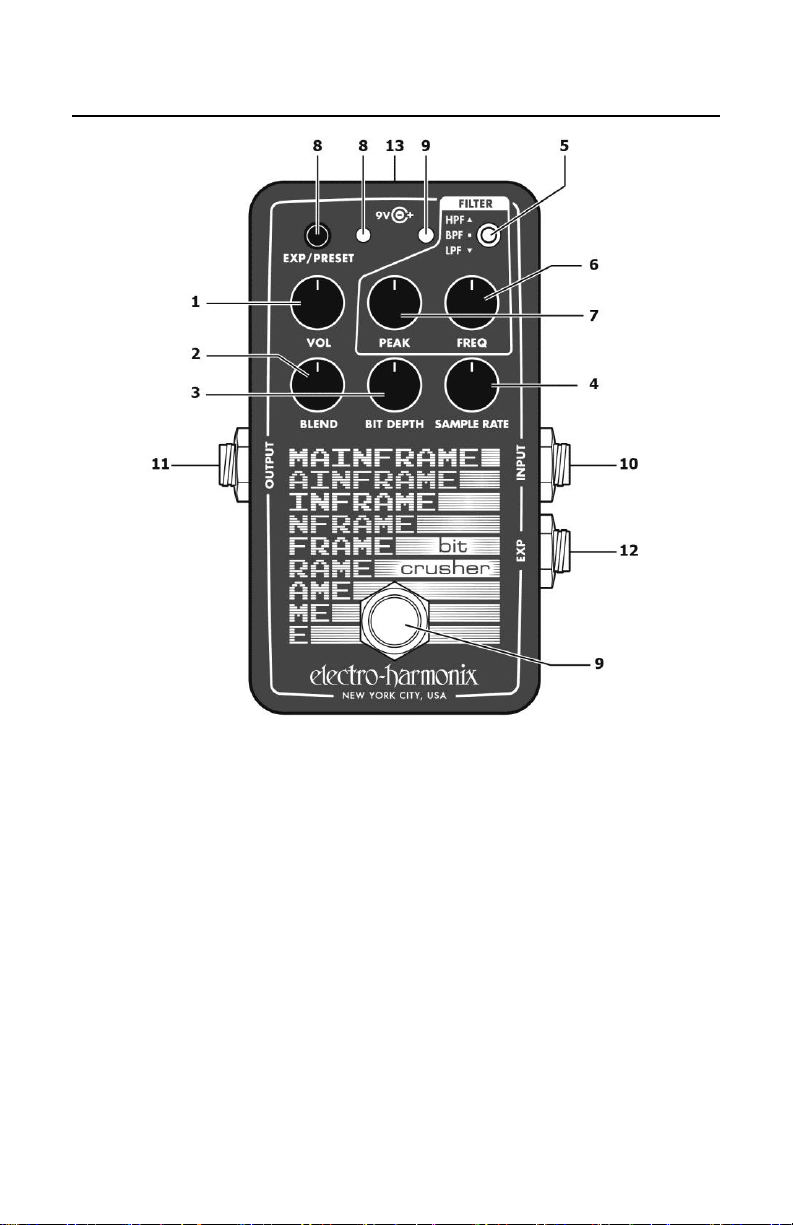
CONTROLS AND CONNECTIONS
1. VOL Knob This knob sets the master output level of the Mainframe.
2. BLEND Knob This knob blends between the dry guitar signal and the
effect signal. As the knob is turned clockwise, the output ranges from
completely dry guitar to a fully effected signal with the filter applied.
3. BIT DEPTH Knob As this knob is turned clockwise, the bit depth of
the signal is
4. SAMPLE RATE Knob As this knob is turned clockwise, the sample
rate of the signal is
5. FILTER HPF/BPF/LPF Switch This toggle switch controls the
direction of the Mainframe’s filter:
HPF: High-Pass Filter
BPF: Band-Pass Filter
LPF: Low-Pass Filter
reduced
, producing a distorted, noisy tone.
reduced
, producing a ringing or glitchy tone.
Page 3

3
6. FILTER FREQ This knob controls the frequency of the Mainframe’s
filter. As the knob is turned up, the frequency increases. The frequencies
cut/passed by the filter vary by the filter type:
HPF: Frequencies above the FREQ knob setting are passed,
frequencies below are cut.
BPF: The FREQ knob controls the center frequency of a pass band.
Frequencies above and below this center frequency are cut.
LPF: Frequencies below the FREQ knob setting are passed,
frequencies above are cut.
Tip: For a tone with no filtering, set the FREQ knob to maximum and set
the toggle switch to LPF.
7. FILTER PEAK This knob controls the resonance of the Mainframe’s
filter. Turning this knob clockwise increases the resonance, producing a
sharper, more cutting tone.
8. EXP / PRESET Button and Green LED This button turns expression
mode or a saved preset on and off. When the Green LED is lit, expression
control is enabled, or the preset is enabled. See pages 6-9 for details on
how to save expression settings or a preset.
9. Footswitch and Red LED Press and release the footswitch to toggle
between bypass and effect modes. When the red LED is lit, the Mainframe
is in effect mode. Double tap the footswitch to enter Sample Rate Tuning
Mode, and tap it once again to exit Sample Rate Tuning Mode and save
the tuned sample rate.
10. INPUT Jack This 1/4" phone jack is the audio input of the
Mainframe. The input impedance is 2M.
11. OUTPUT Jack This 1/4" phone jack is the main audio output of the
Mainframe. The output impedance is 500.
12. EXP Jack Connect an expression pedal or control voltage jack to
allow for external control over every knob on the Mainframe. See pages
6-9 for a description on how to set up and control the Mainframe with an
external expression pedal.
13. 9V Power Jack Plug the output of the Mainframe’s supplied
EHX9.6DC 200mA AC adapter to the 9V power jack located at the top of
the pedal. The Mainframe requires 90mA at 9VDC with a center-negative
plug. Do not exceed 10.5VDC on the power jack.
Page 4
4
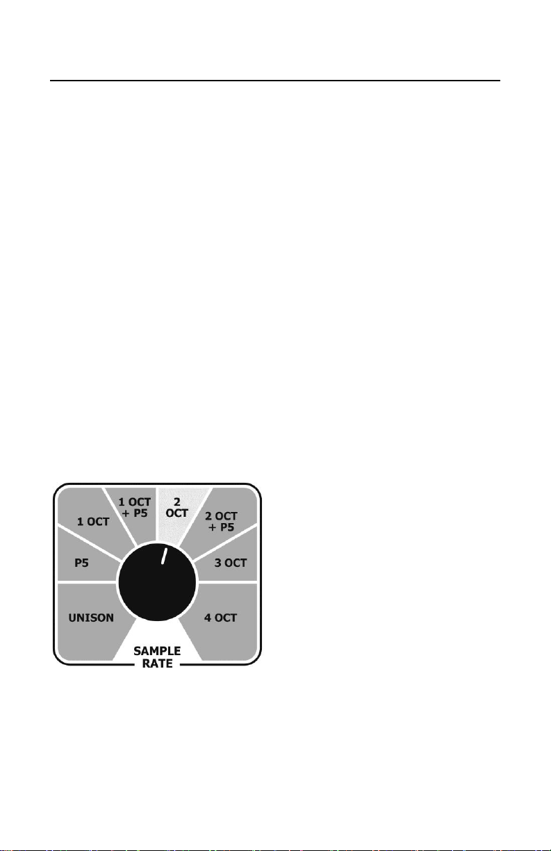
SAMPLE RATE TUNING MODE
In Sample Rate Tuning Mode, the Mainframe analyzes your input signal in
real-time, and sets the sample rate to match the pitch of your signal, or a
set interval above your signal. You can use this mode to lock the sample
rate to a certain pitch for a song, or you can keep it constantly tuning
along with every note you play.
HOW TO TUNE THE SAMPLE RATE
1. Double-tap the footswitch to enter Sample Rate Tuning Mode. The
Red LED will begin blinking in a slow pattern to indicate that the
Mainframe is actively tuning the signal.
Note: You can leave the Mainframe in tuning mode indefinitely and it
will continually tune to your signal.
2. While in Sample Rate Tuning Mode, turn the SAMPLE RATE knob to
select the interval above the guitar pitch at which the sample rate will
be set. See the diagram below for the available interval ranges. The
default interval is two octaves.
3. While in Sample Rate Tuning Mode, tap the footswitch again to lock
the sample rate to whatever note you’re currently playing. You must
be playing a note while pressing this footswitch for the Mainframe to
save the note/interval combination.
INTERVAL RANGES IN SAMPLE RATE TUNING MODE
While in Sample Rate Tuning Mode,
the Mainframe reads the input
signal, then multiplies it by the
interval selected with the SAMPLE
RATE knob (see diagram) to produce
the tuned sample rate of your
choice.
Example: If the interval is set to 2
octaves and the guitar plays an A2
(110Hz), the sample rate will be set
to A4 (440Hz).
Tip: When the interval is set to Unison or Octave, you may hear little to
no sound while in Sample Rate Tuning mode, because the Mainframe is
sampling the signal in the same place every cycle.
Page 5

5
PRESERVING OR DISCARDING THE TUNED SAMPLE RATE
Once locked, the tuned sample rate will be maintained even if the
pedal is powered off and on.
To discard the tuned sample rate, turn the SAMPLE RATE knob, or re-
enter Sample Rate Tuning Mode by double-tapping the footswitch.
The interval range set by sample rate tuning mode is also saved until
the SAMPLE RATE knob is turned again in Sample Rate Tuning Mode.
WHEN USING AN EXPRESSION SETTING OR A PRESET
If a custom expression setting (see pages 6-9) has been set up to control
the sample rate of the Mainframe, Sample Rate Tuning Mode will be
unavailable while expression is active. If a preset is currently active,
turning on Sample Rate Tuning Mode will flag that the preset has been
altered (see page 8).
If you are currently in Sample Rate Tuning Mode while such an expression
setting or preset is loaded, the Mainframe will exit Sample Rate Tuning
Mode and the expression pedal or preset will control the sample rate.
When using the factory default expression setting, the expression pedal
will sweep from no sample rate reduction up to the sample rate set by
Sample Rate Tuning Mode.
Sample Rate Tuning Mode can be used while
setting or preset, either by starting the preset/expression procedure while
Sample Rate Tuning Mode is active, or by turning on Sample Rate Tuning
Mode while creating the expression setting or preset.
creating
an expression pedal
Page 6

6
PRESET AND EXPRESSION PEDAL USE
The Mainframe can store one custom setting in memory. This custom
setting can function as a preset with a snapshot of the toggle switch and
each knob position, or as a custom expression pedal setting allowing you
to sweep any combination of knobs between two saved positions in any
direction. Press the EXP/PRESET button to activate the saved setting.
If no custom setting has been made, by factory default an expression
pedal plugged into the EXP jack will control the sample rate of the
Mainframe. At the heel position, the sample rate will be the full 48kHz. At
the toe position, the sample rate will match the sample rate set by SAMPLE
RATE knob or by Sample Rate Tuning Mode. There is no factory default
preset, so if no expression pedal is used, pressing the EXP/PRESET button
will not load any different sound.
When making a custom setting, the heel and toe positions are saved for
an expression setting, and the toe position is also saved as a preset that
can be recalled without an expression pedal. The toggle switch position is
also saved and can be recalled as a preset or with an expression pedal.
CREATING A CUSTOM PRESET
1. Press and hold the EXP/PRESET button until the green LED starts
blinking slowly.
2. Press and release the EXP/PRESET button again. The green LED starts
blinking rapidly.
3. Turn any of the knobs and the FILTER switch to the settings you would
like to use for the preset. If the controls are already in the position
you would like for the preset, there is no need to turn anything.
4. Press and release the EXP/PRESET button. The green LED will light
solid, indicating that the preset is active. If Sample Rate Tuning Mode
was active during the creation, it will be turned off and the tuned
sample rate will be saved to the preset.
Page 7

7
CREATING A CUSTOM EXPRESSION SETTING
1. Press and hold the EXP/PRESET button until the green LED starts
blinking slowly. This is heel-acquisition mode for an expression setting.
2. Turn any of the knobs to the settings you would like to use for the
heel position of the expression pedal.
3. Press and release the EXP / PRESET button. The green LED will start
blinking quickly, indicating that the heel expression settings have been
saved and the Mainframe has entered toe-acquisition mode.
4. Turn any of the knobs to the settings you would like to use for the toe
position of the expression pedal. Set the FILTER toggle switch to the
position you would like to use for the expression setting.
Note: Any knobs that are in the same position in the heel- and toeacquisition modes will not be included in the expression setting, but
their toe position will still be used when loading a preset without an
expression pedal.
5. If you have an expression pedal plugged in to the Mainframe, you can
sweep the pedal during toe-acquisition to hear how the expression
settings will sound.
6. Press and release the EXP/PRESET button. The green LED will light
solid, indicating that the expression setting or preset is active. If
Sample Rate Tuning Mode was active during the creation, it will be
turned off and the tuned sample rate will be saved to the toe position
of the expression setting.
Tip: You can follow the above instructions to create an expression setting
even if an expression pedal is not plugged in. For this reason, the heeland toe-acquisition settings are always part of the process, whether you’re
creating an expression setting or a preset.
CANCELING PRESET OR EXPRESSION SETTING CREATION
While creating a preset or in the heel- or toe-acquisition modes, you can
cancel the creation of a custom expression setting or preset by pressing
and releasing the footswitch. The previously-saved expression setting or
preset will be loaded, and any new settings will be discarded.
Page 8

8
RECALLING / UNLOADING A PRESET OR EXPRESSION SETTING
1. Press and release the EXP / PRESET button. The green LED will light,
and the Mainframe will load your saved expression setting or preset.
2. If an expression pedal is present, any knobs that are saved to the
expression setting are disabled and the expression pedal controls
those parameters. If no expression pedal is present, the Mainframe
loads the saved positions of all knobs. In both situations, the FILTER
toggle switch’s saved setting will be loaded.
3. To unload the setting or preset, press and release the EXP / PRESET
button. The green LED will turn off, and the toggle switch and any
knobs that were part of the expression pedal setting or preset will
return to What You See Is What You Get operation.
CHANGING PARAMETERS AFTER RECALL
Normally, the green LED lights solid after loading an expression setting or
preset. If the FILTER toggle switched is moved, or if a knob is moved while
a preset is loaded (with no expression pedal connected), the green LED
will blink very rapidly to indicate that the preset has been loaded but has
been altered.
RELOADING ALTERED EXPRESSION SETTINGS OR PRESETS
In the situation where an expression setting or preset has been altered
and the green LED is blinking, press and release the EXP/PRESET button
to recall the saved setting again.
SAVING ALTERED EXPRESSION SETTINGS OR PRESETS
If you would like to save an altered expression setting or preset, press and
hold the EXP/PRESET button for 1 second. The green LED will light solid,
then blink quickly once the new preset has been saved.
ERASING THE CUSTOM EXPRESSION SETTING OR PRESET
Press and hold the EXP / PRESET button. While holding it, press and
release the footswitch. The green LED will blink quickly, then light solid,
indicating that the Mainframe has loaded the factory default expression
setting and the custom expression setting or preset has been erased.
Page 9

9
POWERING UP WITH A SAVED PRESET OR EXPRESSION SETTING
If power is removed from the Mainframe while a preset or expression
setting is active, it will be active when the Mainframe is powered up again,
regardless of knob and toggle switch position.
Note: If there are alterations that haven’t been saved when power is
removed from the Mainframe, the changes will be lost and the saved
version of the preset or expression setting will be loaded.
EXPRESSION PEDAL SPECIFICATIONS AND COMPATIBILITY
The Mainframe accepts an expression pedal with TRS plug or control
voltage (CV) on a TS plug at its EXP phonejack. The polarity of the
expression pedal’s plug must have the Sleeve connected to the heel
position (usually GND), Ring connected to the toe position and the Tip
connected to the wiper. The nominal expression pedal impedance is 10kΩ
though most other values will work fine. Please do not go below 6kΩ on
your expression pedal’s potentiometer impedance. Some suggested
Expression Pedals: EHX Expression Pedal, M-Audio® EX-P, Moog® EP-2
and EP-3, Roland® EV-5 or Boss® FV-500L. Additionally, the EXP IN jack
can be connected to a CV source using a TS plug; the acceptable control
voltage range is 0V to 5V.
Page 10

10
SECONDARY KNOB FUNCTIONALITY
The Mainframe allows you to take even more control over the bit crushing
effects by accessing “hidden” parameters through Secondary Knob Mode.
Use the secondary knob functions to fine tune the exact tone you want
from the Mainframe.
USING SECONDARY KNOB MODE
1. Press and hold the footswitch. While holding the footswitch, press the
EXP/PRESET button. The Red LED will blink to indicate that you are in
Secondary Knob Mode.
2. Turn the PEAK, FREQ, BIT DEPTH, and SAMPLE RATE knobs to edit
the secondary knob parameters. The VOL and BLEND knobs work
normally in Secondary Knob Mode.
3. To exit Secondary Knob Mode, press and release the footswitch or the
EXP/PRESET button. The Red LED will stop blinking. The secondary
knob parameters are saved and will be maintained even if the
Mainframe is power cycled.
Note: The normal knob parameters set by the PEAK, FREQ, BIT DEPTH,
and SAMPLE RATE knobs before entering Secondary Knob Mode are
preserved until those knobs are moved again.
SECONDARY KNOB PARAMETERS
SAMPLE RATE Knob:
When set below 50% (factory default), the Mainframe’s sample rate
reduction can be adjusted continuously through its range.
When set above 50%, the sample rate is constrained to musical
pitches, and is adjusted one half-step at a time.
BIT DEPTH Knob:
When set below 50% (factory default), the Mainframe’s bit crushing
follows the instrument’s amplitude envelope. In this setting, loud and
soft signals will have the same number of bits.
When set above 50%, the Mainframe’s bit depths have fixed levels,
so quiet signals have fewer bits, and are therefore more distorted.
This also results in a gating effect at higher settings.
FILTER FREQ Knob:
When set below 50% (factory default), the filter will be 2nd-order.
When set above 50%, the filter will be 4th-order. This setting applies
to all filter directions (LPF, BPF, HPF). The 4th-order filter more
strongly blocks any frequencies that are being cut by the filter.
Toggle continuous/pitched sample rates
Toggle envelope-following/fixed bit crushing
Toggle 2nd-order/4th-order filter
Page 11

11
FILTER PEAK Knob:
Controls the input gain of the Mainframe. As this knob is turned
clockwise, the gain increases, producing a hard-clipping distortion.
Factory default is with this knob fully counter-clockwise.
ERASING SECONDARY KNOB SETTINGS
To erase all secondary knob settings and restore them to factory defaults,
first unplug the Mainframe from power. Press and hold the footswitch.
Then, while holding the footswitch, plug power back in to the Mainframe.
The Red LED will blink quickly, indicating that all secondary knob functions
have been restored to the factory default.
Input gain
TIPS AND TRICKS
Why adjust the sample rate in a bit crusher?
Using the Mainframe’s sample rate reduction will provide the most
immediate “glitchy old-school computer” sounds, even though it’s not
reducing the signal’s bit depth (“bit-crushing”).
What are good ways to use the filter?
Sample rate and bit depth reduction create artifacts in the audio signal
that are mostly apparent as high-frequency aliasing noises or
distortion. Using the Mainframe’s switchable Low Pass / Band Pass /
or High Pass filter, these noises can be made more subtle, or
strengthened to emphasize the digital effect.
o LPF – Use this to reduce high frequencies. Older digital systems
used low-pass filters to eliminate unwanted noises, so this can be
used to mimic the lo-fi “gritty” sound of old digital equipment.
o HPF – This reduces low frequencies. This can be used to
emphasize the Mainframe’s digital noises, and can also be used to
mimic the weak bass response of small low-cost digital devices
(like toys, handheld games, etc.).
o BPF – This is the previous two filters combined, providing some
of the benefits of each. This can also be used for a wah-like sound
when using an expression pedal, or a cocked-wah sound without
an expression pedal.
Where should this go in the signal chain?
Like nearly any pedal, there is no “right” place to put the Mainframe
in a signal chain, so feel free to experiment with different placements.
As a starting point, it can help to treat the Mainframe as a distortion
pedal, and it can “stack” well before or after other distortion, drive, or
fuzz pedals.
Page 12

12
WARRANTY INFORMATION
Please register online at http://www.ehx.com/product-registration or complete and return
the enclosed warranty card within 10 days of purchase. Electro-Harmonix will repair or
replace, at its discretion, a product that fails to operate due to defects in materials or
workmanship for a period of one year from date of purchase. This applies only to original
purchasers who have bought their product from an authorized Electro-Harmonix retailer.
Repaired or replaced units will then be warranted for the unexpired portion of the original
warranty term.
If you should need to return your unit for service within the warranty period, please contact
the appropriate office listed below. Customers outside the regions listed below, please
contact EHX Customer Service for information on warranty repairs at info@ehx.com or +1718-937-8300. USA and Canadian customers: please obtain a Return Authorization
Number (RA#) from EHX Customer Service before returning your product. Include with
your returned unit a written description of the problem as well as your name, address,
telephone number, e-mail address, RA# and a copy of your receipt clearly showing the
purchase date.
United States and Canada Europe
EHX CUSTOMER SERVICE JOHN WILLIAMS
ELECTRO-HARMONIX ELECTRO-HARMONIX UK
c/o NEW SENSOR CORP. 13 CWMDONKIN TERRACE
55-01 2ND STREET SWANSEA SA2 0RQ
LONG ISLAND CITY, NY 11101 UNITED KINGDOM
Tel: 718-937-8300 Tel: +44 179 247 3258
Email: info@ehx.com Email: electroharmonixuk@virginmedia.com
To hear demos on all EHX pedals visit us on the web at www.ehx.com
Email us at info@ehx.com
COMPLIANCE
Note:
This equipment has been tested and found to comply with the limits for a Class B digital device,
pursuant to part 15 of the FCC Rules. These limits are designed to provide reasonable protection against
harmful interference in a residential installation. This equipment generates, uses and can radiate radio
frequency energy and, if not installed and used in accordance with the instructions, may cause harmful
interference to radio communications. However, there is no guarantee that interference will not occur in
a particular installation. If this equipment does cause harmful interference to radio or television reception,
which can be determined by turning the equipment off and on, the user is encouraged to try to correct
the interference by one or more of the following measures:
Reorient or relocate the receiving antenna.
Increase the separation between the equipment and receiver.
Connect the equipment into an outlet on a circuit different from that to which the receiver is
connected.
Modifications not expressly approved by the manufacturer could void the user's authority to operate the
equipment under FCC rules.
Consult the dealer or an experienced radio/TV technician for help.
The CE logo indicates that this product has been tested and shown to conform
with all applicable European Conformity directives.
 Loading...