

Page 1
User Reference Manual
Manual Notice:
This manual is provided as both a guide
for instruction, as well as a reference to
be kept near by to aid you in everyday
use. In it you will find general information, regarding the Bi-Filter as well as
instructions for real and suggested operating procedures, setup and use. This
manual is subject to change without
notice. Electro-Harmonix is not liable for
errors, direct, indirect, coincidental, or as
a consequence of material contained
within this manual.
32-33 47th Avenue
Long Island City, New York 11101
ph: 718 937 8300 fx: 718 937 9111
www.ehx.com
Page 2

TABLE OF CONTENTS
Introduction 3
Precautions For Safe Use 4
Front Panel 5
Drivers 6
Filters 7
Output mixer 9
Rear Panel 11
Block Diagram:
Audio and Control Signal Paths
13
Specifications 14
Sample Settings 15
Blank Program Sheet 17
Thank you for purchasing the ElectroHarmonix Bi-Filter. Please read this
manual–written to be a reference
guide that you can keep close by–in
order to familiarize yourself with this
unique instrument’s layout. The BiFilter’s sound is wonderful and can
truly set your music apart, but the
key is your creativity.
Copyright
2003 Electro-Harmonix. All rights reserved. Bi-Filter
and Electro-Harmonix and logo are trademarks of
New Sensor/Electro-Harmonix. Product and company
names used within the manual are trademarks of
their respective companies.
Page 3
INTRODUCTION
In the complex world of modulation instruments, Electro-Harmonix introduces the Bi-Filter. It’s a totally analog
instrument, drawing upon the filter designs of the past while utilizing a front panel that brings EVERY relevant control,
for every parameter, to the surface. You are given complete interactive access. Exquisite tone was the bottom line in this
design and the “hands-on control” aspect presents the musician or engineer with the ability to make global, real-time
tone changes that can make the difference between a hit and a miss.
The uniqueness of dual filters working with or against each other presents possibilities only limited by the user's
creativity. The sameness of digital filters, by their very “perfect nature” pale in comparison to the “random” fluidness
that analog filters present. Their uniqueness and full-bodied tone are possibly the most emulated aspects of today’s
modern instruments. Emulations are fine, but the real deal is special.
The Electro-Harmonix Bi-Filter combines two versatile “all analog” envelope and LFO controlled filters in a
configuration that enables the most complex and interesting filter sounds ever possible.
The Bi-Filter continues the tradition of the original Mu-Tron, Beigel Sound Lab and Electro-Harmonix Q-tron products
by using opto-electronic “photo-mod” control. The “state-variable filter” architectures produce the clean and unique
sound, with selectable filter curves preferred by top professionals.
The Bi-Filter uses all analog circuitry, for the best dynamic range and signal-to-noise characteristics of any available
filter product. The effect circuit also uses “true bypass” switching to allow pure unmodified instrument throughput
when the effect is switched off.
The Bi-filter is a single-channel processor, though the filter outputs are individually available. The main effect output is
a single channel MIX of Filter 1, Filter 2 and the input signal. An external FX loop between the input and the filter
allows the use of audio processes without distorting the signal input’s envelope waveform, providing simple access to a
new range of sounds that are reactive to the dynamic of the user—whether engineer, musician or DJ. The Bi-Filter has
all of the best aspects of the past with a sound that makes digital instruments and recordings come alive.
3
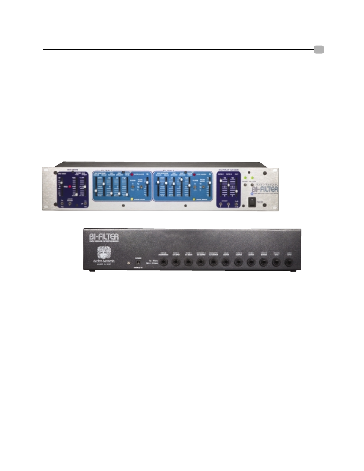
Front Panel
Back Panel
Page 4

PRECAUTIONS FOR SAFE USE
Please read the manual carefully, as it was written to help you understand the operation capabilities of your new
instrument. Carefully review the safety precautions as they ensure a long and trouble free life for your Bi-Filter, as well
as your own safety. Keep your manual in an easily accessible place for future reference.
The following instructions, on this page, are WARNINGS that must be followed.
1. Fluids and moisture: Do not operate this—or any electrical instrument—in an area where it could be exposed to
moisture. This is an instrument. Do not place drinks or fluids on top of it.
2 Placement and ventilation: The Bi-Filter is a rack-mount instrument and thus may be placed in a 2-space rack
location. It may also be placed on a support or table that is designed to handle weight. Placement must be balanced
and even, while still leaving an unobstructed space for proper ventilation. Proper ventilation ensures long life and puts
far less stress on the instrument. Again, keep all fluids away from the storage location. All bracket mountings must be
able to bear the weight of the Bi-Filter.
3. Cleaning: Extreme care must be taken when cleaning the exterior of the Bi-Filter. The exterior may be wiped down
with a damp sponge and an extremely mild detergent. Damp means slightly moist and not wet or saturated.
UNPLUG THE INSTUMENT before any cleaning.
4. Heat: The unit should be situated away from heat sources, or other equipment that produces significant heat. When
the unit is rack mounted, be sure it has proper ventilation.
5. Power Sources: When the unit will be unused for extended periods, disconnect the power supply from the outlet.
Be careful that the power cord is out of the way and specifically away from traveled areas. When connecting or
disconnecting the cable, grasp the plug firmly and push or pull. Do not pull from the cable. Make sure that your
hands are dry.
6. Service Situations: Situations that must be immediately addressed if encountered.
a. Damage to the power cord or to the power supply.
Immediately shutdown and disconnect the power cable.
b. Water, or any other fluid, that has fallen into the interior of the Bi-Filter.
c. Exposure to natural elements such as rain or lightening.
d. Sudden impact of the instrument, such as dropping or a hard external impact.
e. Sudden and noticeable differences in performance and consistency.
f. Functional change where a marked difference in operation is noticed.
Note: All electrical failures must be handled by an authorized service technician.
Do not attempt user service.
A qualified technician will handle it swiftly, accurately and correctly.
For your safety and proper repair, call:
Electro-Harmonix: 718-937-8300. Ask to speak with a service representative and you will be instructed on
how to proceed. You must call in order to receive service.
4
Page 5
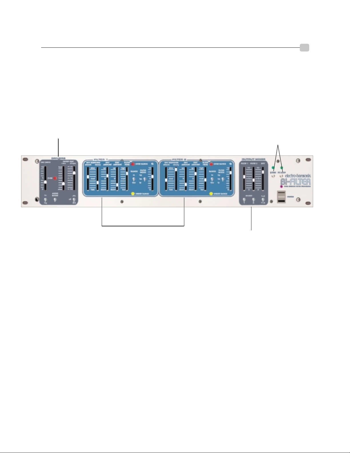
FRONT PANEL
Main Features in the Front Panel
The front panel is organized into the following main sections:
Filter and FX Loop switches: Panel control to bypass the
filters (entire unit) and external FX loop effects
Drivers: Provide the control signal sources to sweep the filters
Filter 1: State-variable voltage controlled filter
Filter 2: State-variable voltage controlled filter,
identical to Filter 1
Output Mixer: Allows mixing of both filter
outputs with the input signal as well as
switchable options for the filters
5
Page 6
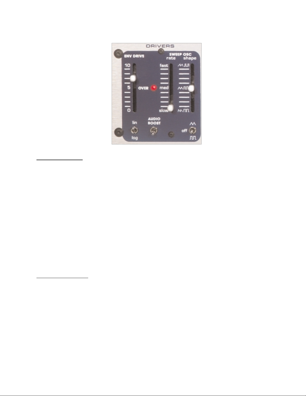
Drivers
Envelope Drive
ENV DRIVE Slider: Controls the envelope follower sensitivity to the input signal. Generally set it so the red OVER
LED blinks on the loudest notes, but all settings produce interesting effects. This is not an all or nothing fader. Different
locations on the slider produce different results.
LOG/LIN Switch: Provides different dynamic response to the input signal.
• The LOG position produces consistent envelope tracking
no matter how soft or aggressive your input signal is.
• The LIN position produces an envelope that follows the
full dynamic range of the input signal.
OVER LED: Lights when the envelope follower is saturated (100%) by the input audio signal
AUDIO BOOST Switch: In the DOWN (OFF) position, the audio signal into the filters is set at unity gain. In the UP
(ON) position, the audio signal into the filters is amplified according to the setting of the ENV DRIVE slider.
Sweep Oscillator
RATE Slider: Controls the Low-Frequency sweep oscillator (LFO) rate.
SHAPE Slider: Changes the LFO waveform duty cycle from 50% in the center position to 10% or 90% at the top or
bottom positions. The Shape Slider can be used to change the shape of a triangle wave to a rising sawtooth wave (in the
top position) or falling sawtooth wave (in the bottom position). When in square wave mode, the Shape Slider controls
the length of the pulse width, from short (in the top position) to long (in the bottom position).
SHAPE Switch: Switches the LFO waveform from Triangle wave in the top position, to Square wave in the bottom
position, to completely Off in the middle position.
Page 7

Filters One and Two
Envelope Response
ATTACK Slider: Controls the time response of the rising or "attack" portion of the envelope. When the slider is in
the FAST (DOWN) position, the envelope will rise with nearly the same attack as your instrument. When in the SLOW
(UP) position, the envelope will rise slowly compared to the attack of your instrument. The range of the attack time is
approximately 5 milliseconds to 1.5 seconds.
DECAY Slider: Controls the time response of the falling or "decay" portion of the signal envelope. When the slider is
in the FAST (DOWN) position, the envelope will fall with nearly the same decay as your instrument. When in the
SLOW (UP) position, the envelope will fall slowly compared to the decay of your instrument. The range of the decay
time is approximately 10 milliseconds to 1.5 seconds.
Envelope Amount
ENV AMOUNT Slider: Controls the amount and direction that the filter is swept by the envelope follower. In the 0
(CENTER) position, the envelope follower does not affect the filter. In the UP direction, the envelope sweeps the filter’s frequency up from the frequency set by the FILTER FREQ slider. In the DOWN direction, the envelope sweeps
the filter’s frequency down from the frequency set by the FILTER FREQ slider. The amount of sweep is continuously
variable depending on the control settings.
NOTE: sweeping one of the filters UP and the other filter DOWN results in an “out of phase” complementary drive.
Oscillator Amount
OSC AMOUNT Slider: Controls the amount and direction of filter sweep by the SWEEP OSC (LFO). In the 0
(center) position, the LFO does not affect the filter. For both the UP and DOWN directions of the slider, the LFO
sweeps the filter’s frequency around the frequency set by the FILTER FREQ slider. In other words, the FILTER FREQ
slider will set the center frequency and the LFO will sweep the filter above and below that center. So to sweep the
entire frequency range, set the FILTER FREQ slider to MED (the center position) and set the OSC AMOUNT slider to
either the maximum UP or DOWN positions. The difference between the UP and DOWN positions is that in the UP
position the LFO is non-inverted, in the DOWN position the LFO waveform is inverted. If there is a rising sawtooth
set up in the sweep oscillator section, and the OSC AMOUNT slider is set to the DOWN position, the waveform will
become a falling sawtooth. NOTE: Setting the OSC AMOUNT of one filter UP and the other filter’s OSC AMOUNT
DOWN, results in an "out of phase" complementary drive.
NOTE: FILTER 1
and FILTER 2
HAVE IDENTICAL
CONTROLS AND
RESPONSE, BUT
ARE SEPARATELY
ADJUSTABLE.
7
Page 8

Filters One and Two (Continued)
Filter, Frequency and Range Controls
FILTER FREQ Slider: Sets the filter frequency within its operating range. When no envelope or LFO signals are
present, the frequency of the filter is set by the position of this slider. To perform a manual
filter sweep, simply push this slider up or down.
RANGE Switch: Changes the sweep range of the filter:
LOW position gives the filter a sweep range from 150 Hz to 5 kHz.
HI position gives the filter a sweep range from 350 Hz to 12 kHz .
OVER/UNDER RANGE LEDs: Indicates that the filter is being swept to its limits of the frequency range.
OVER RANGE RED LED: Indicates the frequency has been swept to or above
the maximum range of the filter.
UNDER RANGE YELLOW LED: Indicates the frequency has been swept to or
below the minimum range of the filter.
FILTER MODE Switch: Selects the type of filter characteristic:
LP: Low Pass Mode turns the filter into a Low Pass filter which only passes audio below the
cutoff frequency. With no envelope or LFO modulation, the cutoff frequency is set by the
FILTER FREQ slider and RANGE switch.
BP: Band Pass Mode turns the filter into a Band Pass filter which only passes audio in the
region around the center frequency. With no envelope or LFO modulation, the center frequency is set by the FILTER FREQ slider and the RANGE switch.
HP: High Pass Mode turns the filter into a High Pass filter which only passes audio above the
cutoff frequency. With no envelope or LFO modulation, the cutoff frequency is set by the
FILTER FREQ slider and RANGE switch.
Q Slider: Adjusts the filter’s quality factor or “Q”, also known as resonance. With this slider you have control of the
filter’s “peak” from a flat roll-off curve to a highly emphasized peak at the cutoff or center frequency. The higher the
control setting, the greater the peak of the filter, which will produce a more pronounced filter effect.
Page 9

Output Mixer
Output Mixer Section
OUTPUT MIXER: Provides a 3 channel audio mixer where the signals from Filter 1, Filter 2 and the original Dry signal can all be mixed together. These sliders give the user precise control over their sound, enabling the user to “season
to taste” the amount of filtering versus the amount of original signal.
OUTPUT LEVEL Controls:
FILTER 1 Slider: Mixes in the Filter 1 output signal.
FILTER 2 Slider: Mixes in the Filter 2 output signal.
DRY Slider: Mixes in the original un-filtered audio signal
(AFTER the AUDIO BOOST switch).
INVERT Switches: These switches give the user the ability to invert the signal going into each filter. When listening to
one of the filters alone, flipping the Invert switch will have no affect on the sound. If both filters as well as the Dry signal are all mixed together and one or both of the filters have their Invert switch on (along with the right settings for the
rest of the sliders), then the user will obtain phase shifter sounds from the Bi-Filter.
INVERT 1 Switch: Inverts the signal going into Filter 1. When the switch is in the
DOWN position, the Invert function is OFF. When the switch in the
UP position, pointing to the word INVERT, the Invert function is
ON. The INVERT 2 switch works the same way.
INVERT 2 Switch: Inverts the signal going into Filter 2.
1 + 2 / 1 2 (FILTER PATH) Switch: Determines the audio signal path through the filter sections.
1 + 2 Position: Puts the filters in parallel. The signal at the Audio Input jack is fed into both Filter 1 and
Filter 2.
1 2 Position: Puts the filters in series. The signal at the Audio Input jack is first fed
into Filter 1. The output of Filter 1 then goes into the input of Filter 2.
The output of Filter 1 will still be available at its mix slider and at its
output jack.
9
Page 10

Bypass Section
FILTERS Switch and LED: Puts the entire Bi-Filter into TRUE BYPASS MODE or EFFECT MODE. When the
switch is in the DOWN position, the FILTERS LED, above it, will be off and the entire unit is in true bypass mode. In
true bypass mode, the signal into the AUDIO INPUT Jack is connected directly to the MAIN OUTPUT Jack and disconnected from the Bi-Filter circuit. When the switch is in the UP position, the FILTERS LED will be on and the unit is
in effect mode. In effect mode, the signal into the AUDIO INPUT Jack is connected to the Bi-Filter circuit. The output
of the OUTPUT MIXER section of the Bi-Filter is then connected to the MAIN OUTPUT Jack.
FX LOOP Switch and LED: Switches the effects send and return loop on or off. When the switch is in the DOWN
position, the FX LOOP LED will be off and the external effects loop that is connected to the EFFECTS SEND and
EFFECTS RETURN jacks will bypassed. When the switch is in the UP position, the FX LOOP LED will be on and the
external effects loop connected to the EFFECTS SEND and EFFECTS RETURN jacks will be engaged. When FX
LOOP is on, the external effects loop will be part of the Bi-Filter circuitry. Special Note: When nothing is plugged into
the EFFECTS RETURN jack, the FX LOOP Switch will have no function. This switch will only appear to be working
when a cable is plugged into the EFFECTS RETURN jack of the Bi-Filter.
Power Switch
POWER Switch and LED: Controls the AC power to the entire unit. The BLUE LED above the POWER Switch
indicates the Bi-Filter is ON. The unit is ON when the switch is in the up position, OFF when the switch is in the
down position.
Page 11

REAR PANEL
123456789101112
1. AUDIO INPUT: Main audio input into the Bi-Filter. Signals from a mixing board or a musical instrument
go here.
2. EFFECTS SEND: EFFECTS SEND is an Output jack that provides a buffered, preamplified version of the
signal present at the AUDIO INPUT jack. This signal can be used to go into an external
effects loop. The output present at this jack is after the AUDIO BOOST switch on the
front panel.
3. EFFECTS RETURN: EFFECTS RETURN is an Input jack that accepts the signal from an external effects loop.
NOTE: The EFFECTS SEND and EFFECTS RETURN jacks allow the use of audio
effects BEFORE the filter stages. It is therefore possible to put effects on the signal before
the filters but still obtain the envelope from the original signal. It is also possible to have
one instrument’s envelope modulate another instrument: connect one instrument into the
AUDIO INPUT jack for its envelope and connect another instrument into the EFFECTS
RETURN jack to go through the filters.
4. FILTER 1 OUTPUT: Audio Output from Filter 1 only. The output is before the FILTER 1 MIX slider on the
front panel, so the full Filter 1 output will always be available no matter the position of its
mixer slider. NOTE: There will be no audio output from this jack when in bypass mode
due to the TRUE BYPASS switching of the input signal.
5. FILTER 2 OUTPUT: Audio Output from Filter 2 only. The output is before the FILTER 2 MIX slider on the
front panel, so the full Filter 2 output will always be available no matter the position of its
mixer slider. NOTE: There will be no audio output from this jack when in bypass mode
due to the TRUE BYPASS switching of the input signal.
6. MAIN OUTPUT: Main audio Output for the Bi-Filter. The signal on this jack is the output of the mixer section on the front panel. So there will be a mix of Filter 1, Filter 2 and the Dry input signal
coming out of the MAIN OUTPUT jack. When in TRUE BYPASS mode, the DIRECT
unmodified instrument signal will be output on this jack.
11
Page 12

7. ENVELOPE 1 CV OUTPUT: This jack Outputs a Control Voltage of Envelope Follower 1 which modifies Filter
1. The range of this output is 0 - 14 Volts DC.
8. ENVELOPE 2 CV OUTPUT: This jack Outputs a Control Voltage of Envelope Follower 2 which modifies Filter
2. The range of this output is 0 - 14 Volts DC.
9. FILTER 1 CV INPUT: Accepts a DC Control Voltage that controls the sweep of Filter 1 through its entire
range. This control voltage is ADDED to the control signals from the Envelope
Follower, LFO and Filter Frequency slider on the front panel. You may also plug
an expression pedal (with a TRS connector) into this input, to control the sweep of
the filter with a pedal. The range of this input is 0 - 5 Volts DC. NOTE: You will
control the sweep of both Filter 1 and Filter 2 with only this jack if nothing is
plugged into the FILTER 2 CV INPUT jack.
10. FILTER 2 CV INPUT: Accepts a DC Control Voltage that controls the sweep of Filter 2 through its entire
range. This control voltage is ADDED to the control signals from the Envelope
Follower, LFO and Filter Frequency slider on the front panel. You may also plug
an expression pedal (with a TRS connector) into this input, to control the sweep of
the filter with a pedal. The range of this input is 0 - 5 Volts DC. NOTE: If nothing
is plugged into this jack but there is a Control Voltage present in the FILTER 1 CV
INPUT jack, it will sweep both filters.
11. BYPASS FOOTSWITCH: Connects to a 2 channel remote footswitch. The tip of the footswitch’s plug con-
trols the FILTER Bypass function, which bypasses the entire Bi-Filter. The ring of
the footswitch’s plug controls the FX LOOP Bypass function. When a footswitch
is plugged into this jack, the front panel bypass switches are taken out of the circuit and will not function.
12. POWER JACK: This jack accepts the power for the Bi-Filter from the 18VAC/1000mA AC
ADAPTER supplied with the Bi-Filter. Plug the barrel connector from the AC
ADAPTER into this jack.
123456789101112
REAR PANEL (Continued)
WARNING: Use only the 18VAC/1000mAAC adapter the Bi-Filter comes supplied
with. Do not use any other AC adapters. Using other AC adapters, even
those made by Electro-Harmonix, could cause harm to the unit, the
adapter or you.
12
Page 13

BLOCK DIAGRAM:
AUDIO AND CONTROL SIGNAL PATHS
y
o
Input
F
s
W
51
e
oos
W
der
To
t
o
Foots
ch
do
p
F
p
F
p
y
W
G
Foots
ch
Input
er
F
1
do
p
W
R
e
M
de
Q
r
Inve
W
Mode
Q
F
CV
do
p
R
e
F
2
1 2
F
e
W
der
F
1
F
2
y
der
Fil
e
s
y
s
W
F
i
h
B
TIP
t
t
F
2
F
1
t
t
d
pe
g
Gene
Fro
t
F
1
D
y
pe
ck
ck
D
y
F
2
pe
R
e
e
p
Osc
O
F
1
t
F
y
F
1
F
CV
Input
Output
CV
F
2
t
der
CV
t
F
y
F
2
der
F
CV
Input
OSC
t
F
2
der
OSC
t
F
1
der
F
CV
F
CV
F
CV
13
Invert
ilter
Invert S
wn
u
ilter 1
Slide
ang
o
Audi
Bypass
wit
Effects Return
Unit Bypass
Rela
ilter
Bypass S
BUF
Sli
Driv
X1-X
Audi
B
t S
wn
u
ENV Circui
X Loo
Bypass Rela
X Loo
Bypass S
Dr
Mixer Sli
ilter
Mixer Sli
Unit Bypas
Rela
ootsw
ypass
tc
Bypass S
t
r
Effects Sen
Outpu
Main
Outpu
ilter
Outpu
Bypass
wit
RIN
ilter 1
m BOOST Circui
ilter 2
BUF
BUF
Envelo
Lin/Lo
rator
ilter
Envelo
Atta
Slider
ilter
Envelo
Atta
Slider
Slider
eca
Slider
eca
ilter
requenc
Slider
ilter
ENV Amoun
Slider
ilter
requenc
Sli
ilter
ENV Amoun
Sli
+
ilter
rial/Parallel S
S
Inverter
ilter
rt S
wn
u
Slider
ilter 2
ang
ilter
Mixer Slider
ilter
Outpu
ilter 1
ENV 1
ENV 2
Outpu
ilter 2
ilter
FF
Swee
Slider
at
illator
Shap
Slider
Amoun
Sli
ilter
Amoun
Sli
Page 14

• Maximum Input Signal Level: 6.3 VRMS (+18 dBV)
• Maximum Control Voltage Input Level: 5 VDC.
• Minimum Control Voltage Input Level: 0 VDC.
• Maximum Signal Gain (Q Control = 10): 34 dB
• Minimum Signal Gain (Q Control = 1): 0 dB
• Sensitivity for Full Envelope Sweep: (ENV Drive Control = 1): 1.0 VRMS
(ENV Drive Control = 10): 20 mVRMS
• Filter Frequency Range: LO: 150 Hz to 5 kHz Resonant Frequency
HI: 350 Hz to 12 kHz Resonant Frequency
• Frequency Response (Dry Output): Beyond 20 Hz to 20 kHz +- 0.5 dB
• Dynamic Range (Measured at output): 105 dB best case
Residual Noise Level: -93 dBV worst case
Maximum Undistorted Output: +12 dBV worst case
• Sweep Oscillator (LFO) Rate Range: 0.02 Hz (50 s) to 30 Hz
• Envelope Attack Time: 5 milliseconds to 1.5 seconds
• Envelope Decay Time: 10 milliseconds to 1.5 seconds
• Envelope Voltage Output: 0 to 14 Volts
Note: All Specifications are subject to change.
SPECIFICATIONS
Page 15

Try this setting first with a funky rhythm!
Slow Dual Envelope Sweep: Smooth slow envelope up sweep with two filters
Highpass Dual Down Drive: Chunky sweep, which is good for heavily accented lines and adds percussiveness to your
attack. Try out different settings of the Filter RANGE, MODE, INVERT, and MIX controls.
Gated Envelope Sweep: Both the LFO and Envelope are acting on the Filters to produce a setting that sounds as if the
envelope is being gated by the LFO.
SAMPLE SETTINGS
15
Page 16

LFO Phase Sweep: The internal LFO's sweep the filters and sound a bit like—but different than—a phasor.
Envelope and Oscillator: Sweep one filter with the Envelope and the other filter with a fast LFO, for a dynamic AND
rhythmic filter effect.
Pop-Tone: A very dramatic effect, especially useful on staccato solos and rhythms, for guitar and bass.
Sci-Fi Sweep: The LFO is acting on the Filters with a falling sawtooth waveform. In the Output Mixer section,
the filters are set to sound like a Phasor when swept.
SAMPLE SETTINGS (Continued)
16
Page 17

BLANK PROGRAM SHEET
Please photocopy for your own reference.
17
 Loading...