


25w
http://users.otenet.gr/~athsam/electrocompaniet.htm
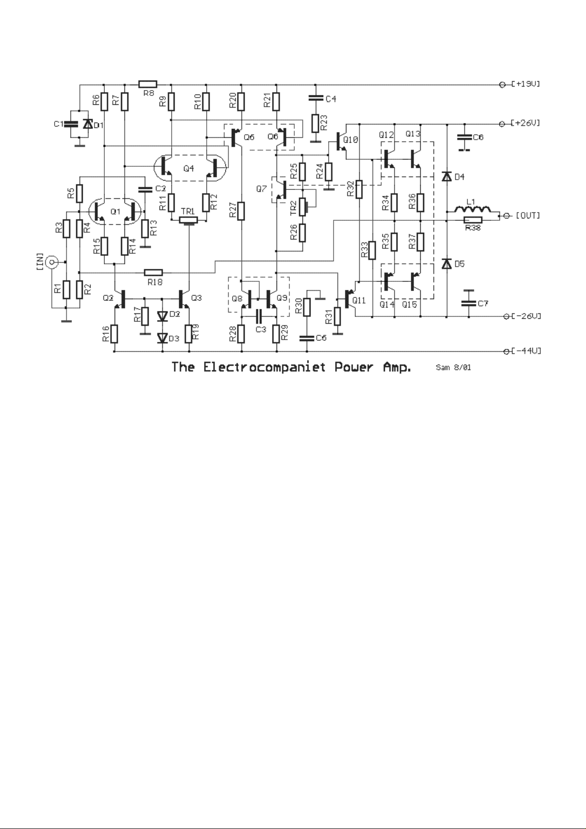
ith output of 25W per channel into 8ohms, this power amplifier, presents exceptional interest for
he circuit is designed with regard to reducing T.I.M (Transient Intermodulation Distortion).
bserving the circuit of amplifier, we will see that it is separated in four stages. The three first are
e
the first differential stage Q1 is BCY87 (Philips), in a metal case. The input impedance R1 of the
Ferranti).
the second differential stage Q4- BCY89 (Philips), trimmer TR1, adjusts for output offset
d
he third differential stage Q5-Q6, is supplied with current from current mirror Q8-Q9. These
, 8,
7 and TR2 are a Vbe multiplier, in thermal contact with the output stage
he output stage is the classic Darlington pair for positive and negative supplies. D4 & D5 protect
W
many, and it applies enough technological solutions, that we do not find in a lot of other amplifiers.
T
O
full differential amplifiers (in thermal equilibrium, for minimal change in characteristic with
temperature variation) and the fourth stage of the classic Darlington arrangement, with Vb
multiplier transistor so set bias current in the output stage.
In
amplifier is very low 1.8K, compared to most amplifiers which are between 47K-100K.
The two first differential amplifiers are supplied by current sources Q2 and Q3 ZTX384 (
The base of Q1 is applied the negative feedback via R18, R2, R4. Compensation for high
frequencies is provided by R5 and C2.
In
voltage. The constant current sources are roughly 0.2mA for first stage and 0.4mA for secon
stage.
T
function to increase the speed and the linearity of stage. Thermal balance is ensured as Q5, 6
9 are all in thermal contact.
Q
T
the output transistors from speaker back emf.
 Loading...