

Page 1
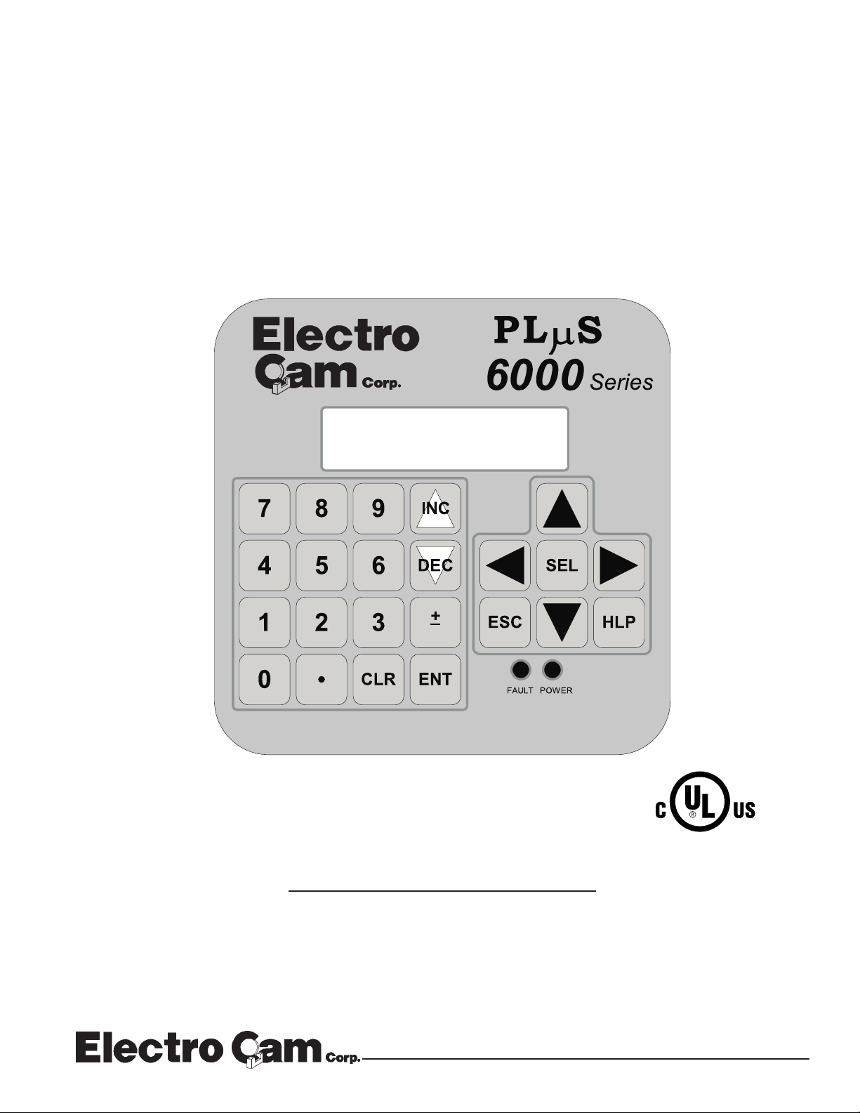
PLµS™ PS-6244 Series
Programmable Limit Switch
PGM:1 RPM:1500
MENU< POS: 180
Programming &
Installation Manual
4/99
13647 Metric Rd • Roscoe, IL 61073 U.S.A. • 815-389-2620 • FAX 815-389-3304 • 800-228-5487 (USA & Canada)
Page 2

Copyright © 1999
All Rights Reserved
Neither this document nor any part may be reproduced or transmitted in
any form or by any means without permission in writing from the publisher.
, PLµS, SLIMLINE, and PLµSNET are all registered trademarks of
1-2 Introduction
Page 3

Table of Contents
Section 1—Introduction
Mechanical Cam Switches .............1-5
Programmable Limit Switches........1-5
PS-6244 Description ......................1-6
Basic Terminology..........................1-7
PS-6244 Features ..........................1-8
Section 2—Installation & Wiring
General Mounting & Wiring ............2-1
Mounting Dimensions.....................2-2
Terminals & Components
PS-6244-17 ...............................2-3
PS-6244-25 ...............................2-4
Controller Input Wiring....................2-5
Output Wiring .................................2-8
Keypad Wiring ................................2-12
DIP Switch Configurations..............2-13
Communications Wiring..................2-15
Encoder Wiring...............................2-16
Fuse Tester & Fuse Replacement..2-17
Output Transistor Replacement......2-18
Section 3—Programming
Keypad Overview ...........................3-1
Menu Tree .....................................3-2
Initial Programming.........................3-3
Functions (Alphabetically)
Analog Output............................3-4
Analog Quantity .........................3-5
Communications........................3-6
Default Program ........................3-7
Enable Codes ............................3-8
Enable Options ..........................3-10
Increasing Direction...................3-10
Input ANDing .............................3-11
Input Status ...............................3-11
Keyboard Quantity.....................3-12
Main Screen ..............................3-12
Memory Tests............................3-13
Motion ANDing ..........................3-14
Motion Detection .......................3-15
Section 3—Programming Continued
Offset.........................................3-15
Output Status ............................3-16
Password...................................3-16
Per Channel Enable ..................3-17
Program Copy ...........................3-18
Program Select Mode................3-18
Pulse Copy ................................3-19
Rate Setup ................................3-20
RPM Update Rate .....................3-21
Scale Factor ..............................3-21
Setpoint Use..............................3-22
Setpoints ...................................3-22
Shift Position .............................3-23
Shift Register ANDing ...............3-24
Software Version .......................3-26
Speed Compensation................3-27
Toggle RPM ..............................3-28
Section 4—Troubleshooting
Controller Diagnostics ....................4-1
Keypad Diagnostics .......................4-2
Encoder Troubleshooting ...............4-3
General Troubleshooting................4-4
Fuse Part Numbers ........................4-6
Section 5—Speed Compensation
Introduction to Speed Comp ..........5-1
Standard Speed Comp...................5-2
Leading/Trailing Speed Comp........5-4
Negative Speed Comp ...................5-5
Speed Comp Guidelines ................5-6
Section 6—PluSNET II™ Communications
Appendix
Controller Specs.............................A-1
Module Specs ................................A-2
Factory Defaults .............................A-3
Index ..................................................I-1
Form to Record Setpoints
1-3 Introduction
Page 4

WARRANTY
1. Electro Cam Corp. warrants that for a period of twelve (12) months from the date of shipment to
the original purchaser, its ne w product to be free from defects in material and workmanship and
that the product conforms to applicable drawings and specifications approved by the Manufacturer. This warranty period will be extended on Distributor or OEM orders to a maximum of
eighteen months to take into consideration Distributor or OEM shelf time.
2. The remedy obligations of Electro Cam Corp. under this w arranty are e xclusive and are limited to
the repair, or at its option, the replacement or refund of the original purchase price of any new
apparatus which proves def ective or not in conf ormity with the drawings and specifications. Shipment of the claimed defectiv e product to Electro Cam Corp. shall be at the cost of the consumer.
Shipment of the repaired or replacement product to the consumer shall be at the cost of Electro
Cam Corp. All claims must be made in writing to Electro Cam Corp., 13647 Metric Road, Roscoe,
IL 61073 USA.
3. In no event, and under no circumstances, shall Electro Cam Corp. be liable for:
a. Any product damaged or lost in shipment. Inspection for damage should be made before
acceptance or signing any delivery documents releasing responsibility of the delivering carrier.
b. Product failure or damages due to misuse abuse, improper installation or abnormal condi-
tions of temperature, dirt or other contaminants as determined at the sole discretion of Electro
Cam Corp.
c. Product failures due to operation, intentional or otherwise, above rated capacities as deter-
mined at the sole discretion of Electro Cam Corp.
d. Non-authorized expenses for removal, inspection, transportation, repair or rework. Nor shall
the manufacturer ever be liable for consequential and incidental damages, or in any amount
greater than the purchase price of the equipment.
4. There are no warranties which extend be yond the description on the f ace hereof. This warranty is
in LIEU OF ALL OTHER WARRANTIES, EXPRESSED OR IMPLIED INCLUDING (BUT NOT
LIMITED T O) ANY IMPLIED WARRANTIES OF MERCHANTABILITY OR FITNESS FOR A PARTICULAR PURPOSE, ALL OF WHICH ARE EXPRESSLY DISCLAIMED. Any legal proceeding
arising out of the sale or use of this apparatus must be commenced within (18) months of the date
of shipment from the manufacturer.
1-4 Introduction
Page 5

Mechanical Cam Switches
Mechanical Cams The PS-6244 Programmable Limit Switch electronically simulates mechanical cam
switches. A cam switch consists of a roller limit switch whose arm rides on a cam as
shown in Figure 1. The cam shaft is driven by a machine at a 1:1 ratio, so that the cam
switch turns on and off at specific positions in the machine cycle. Cam limit switches
have the following disadvantages:
• The roller, the cam, and the limit switch wear out.
• The machine must be stopped during adjustment.
• On/off patterns are limited, and changing the pattern may require replacement of one
cam with another. For example, a cam that switches on and off twice in one revolution would need to be replaced with a different cam if three on/off pulses per revolution were required.
• They cannot run at high speeds because of contact bounce and excessive mechanical wear.
Figure 1—Basic Cam Switch
Programmable Limit Switches
PS-6244’s & Encoders The PS-6244 Programmable Limit Switch uses a quadrature encoder (Figure 2) in-
stead of a cam to indicate machine position. A quadrature encoder uses optical discs to
generate streams of pulses that can be processed by the PS-6244. From the encoder
signals, the PS-6244 can determine shaft position, direction, and speed. The encoder
is usually coupled to a machine shaft at a 1:1 ratio so that one encoder shaft rotation
corresponds to one machine cycle. Encoders have no brushes, contacts, or any frictional moving parts to wear out.
Based on the encoder signal, the PS-6244 Programmable Limit Switch turns electrical
circuits, or “Outputs,” on and off, simulating the mechanical roller limit switch. Because
the combination PS-6244/encoder system is completely electronic and has no frictional
parts, it offers several advantages over mechanical cam switches:
• Long service life with no parts to wear out.
• “On” and “off” points can be adjusted instantly from the keypad; there are no cams to
rotate or replace.
• Adjustment is possible with the machine running or stopped.
• Programmable logic allows complex switching functions that are impossible with
mechanical cams.
• Operation at speeds up to 1500 RPM.
1-5 Introduction
Page 6
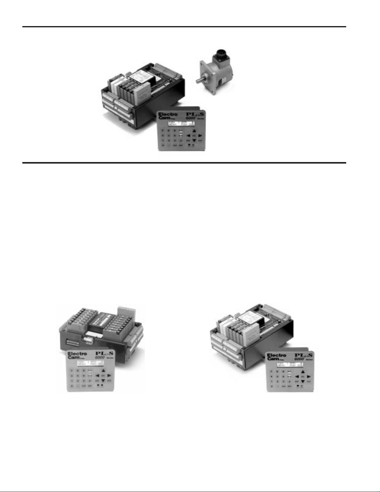
Programmable Limit Switches
Figure 2—PS-6244-24-N16M09 Programmable Limit Switch and Quadrature Encoder
Typical
Quadrature Encoder
(BEI H25D shown)
Controller
PS-6400
Keypad/Display
PS-6244 Description
Controller & Keypad PS-6244 Series Programmable Limit Switches consist of two main components: the
controller and the keypad/display. The controller houses the microprocessor, associated circuitry, and all of the I/O circuits. This eliminates the need for external I/O racks.
Figure 3—PS-6244 Models
A separate 1/4 DIN keypad/display provides a complete user interface from which every aspect of the controller’s operation can be monitored and programmed. Multiple
keypads can be connected to a single controller. In addition, when interfaced to a PLC
or other computer, the controller can be used without a keypad/display. When properly
mounted with the gasket provided, the keypad/display meets NEMA 4X standards. A
clear silicon rubber boot assembly is available to provide protection for installations
where harsh washdown chemicals are used.
The PS-6244 Series is available in two models: the PS-6244-24-M17 and the PS-624424-X16M09 Both are described in Figure 3.
PS-6244-24-N16M09 Controller—Up to 25 OutputsPS-6244-24-M17 Controller—Up to 17 Outputs
The PS-6244-24-M17 has 17 total outputs:
• Outputs 1 through 15 can accept AC or DC output
modules for driving “real world” devices such as
solenoids, valves, or glue guns.
• Output 16 will accept an AC or DC module, or an
analog module that generates a control signal
proportional to RPM.
• Output 17 is dedicated to analog output.
1-6 Introduction
The PS-6244-24-N16M09 has 25 total outputs:
• 16 transistor outputs are built into the controller.
• Outputs 17 through 23 can accept AC or DC output
modules for driving “real world” devices such as
solenoids, valves, or glue guns.
• Output 24 will accept an AC or DC module, or an
analog module that generates a control signal
proportional to RPM.
• Output 25 is dedicated to analog output.
Page 7

Basic T erminology
The following terms will be used throughout this manual to explain PS-6244 installation,
programming and operation:
Outputs (channels) An “output,” or “output channel,” refers to an external circuit that the PS-6244 controls
based on encoder position or speed. Outputs can be one of two types:
Switching outputs turn circuits on or off.
Analog outputs generate a control signal that is proportional to RPM.
Setpoints “Setpoints” are the points within one rotation of the encoder at which an output channel
turns on or off. Setpoints can be programmed into an output channel through the keypad/display, or they can be downloaded from a computer or PLC through serial communications. The PS-6244 can turn any given output on and off multiple times within
one rotation.
Pulses A “pulse” is the “on” period between the time an output is turned on and off. The “on”
point is the leading edge of the pulse, and the “off” point is the trailing edge. When
multiple “on” and “off” points are programmed into one output channel, the output is
said to have multiple pulses.
Programs Suppose that 15 output channels on a cartoner are programmed with setpoints to fold
and glue a certain size carton. These settings could be stored as a “program.” Then, the
15 output channels could be re-programmed with different setpoints for a different size
carton. This second set of setpoints could also be stored as a program. To change
carton sizes, an operator could simply activate the correct program, and the corresponding setpoints would take effect.
The use of programs can provide tremendous advantages over mechanical cam switches. Standard PS-6244’s can store up to 48 programs. The active program can be selected through the keypad/display, mechanical switches, direct PLC interface, or serial
communication messages.
Inputs (hardware inputs) In addition to accepting a signal from the encoder, the PS-6244 can accept up to 16
input signals from mechanical switches, relay contacts, DC two- or three-wire sensors,
solid state DC output modules, or PLC DC outputs. The PS-6244 hardware inputs are
dedicated to specific functions involving program selection and controlling output channels based on sensor signals.
1-7 Introduction
Page 8

PS-6244 Features
Programming Access Three levels of programming access are provided: Operator, Setup, and Master. Each
level can be assigned a password that must be entered to allow programming at that
level. In addition, the Operator and Master levels can be activated on an individual
keypad through hardware terminals on the back. Careful use of programming access
levels can provide key personnel the flexibility they need in programming the controller,
while protecting settings against accidental or unauthorized changes.
Speed Compensation Speed compensation advances the setpoints for an output channel as machine speed
increases. This eliminates the need to manually adjust the settings for fixed-response
devices whenever machine speeds are changed. Speed compensation provides greater
accuracy, higher production speeds, and reduced downtime for machine adjustment.
Motion ANDing Two speed ranges can be programmed into the controller, and output channels can be
ANDed with either speed range so that they will be disabled unless the machine speed
is within the specified range. A common use for this feature is disabling outputs to glue
valves to turn off the glue flow if the machine stops.
Input ANDing An output channel may be ANDed with one of eight input signals so that the output is
disabled unless the input signal is present.
Shift Register ANDing The PS-6244 includes a shift register that can turn output channels on or off up to 255
revolutions after a signal is applied to Input Terminal 16, Figure 7. The terminal is usually connected to a product sensor.
Analog Outputs PS-6244 controllers can drive up to two analog output modules whose output signal will
be linearly proportional to RPM. The analog signal level at zero RPM can be programmed,
as well as the RPM that corresponds to maximum signal. No measuring equipment is
required for initial setup, and calibration is not needed. Typical uses for the analog
output are to control glue pressure as machine speeds change, or to match speeds of
other equipment to the machine being controlled by the PS-6244.
Serial Communication Using Electro Cam Corp.’s PLuSNET software for IBM-PC compatible computers, the
PS-6244’s programs can be saved to a disk file or loaded from a disk file to the PS-
6244. The programs can be printed or edited using the computer. Individual commands
may also be sent to the PS-6244 to change settings while running.
Washdown Boot A clear silicon rubber boot can be supplied that fits over and around the keypad face.
The back of this boot provides sealing between the back of the keypad and the panel.
The boot is transparent and pliable, allowing the keypad to be viewed and operated
through it. In addition to preventing contamination from harsh chemicals, the boot also
protects the keypad from grease, oil, dirt and normal wear that could otherwise shorten
its life.
1-8 Introduction
Page 9

General Mounting & Wiring
Controller The controller body mounts on a DIN rail as shown in Figure 4.
Keypad/Display Mount the keypad/display to a panel using the four studs on the back of the keyboard.
Enclosures are available from Electro Cam if an appropriate mounting location does
not exist.
DIP Switches For convenience, set the DIP switches on the side of the controller and keypad to
their proper positions before mounting the units in a panel. See page 2-13 for DIP
switch information.
Environment 1. Allow space at both sides and the top of controller for terminal blocks to be un-
plugged.
2. Ambient temperature range is +32° to +130° F (0° to +55°C)
3. Locate the controller and keypad away from devices that generate electrical noise,
such as contactors and drives.
4. Use the keypad/display gasket provided to prevent contaminants from getting into
the cabinet.
Terminal Blocks All terminal blocks can be unplugged from the controller. Each block is keyed so it
cannot be plugged into the wrong socket. All terminals are labelled on each block.
Wiring Guidelines Follow normal wiring practices associated with the installation of electronic controls.
Some guidelines are:
CAUTION
1. Route input and output wiring away from high voltage, motor drive, and other high
level control signals.
2. Use shielded cables for encoder, input, transistor output, and communication circuits. Also shield module output circuits that are driving low current electronic input
circuits.
3. Ground shielded cables at the PS-6244 end only (except for encoder cable). Use
any of the screws on the controller back for grounding.
4. Use appropriate suppression devices where module outputs are directly driving inductive loads.
Power Supply Wiring Connect a 20 to 30 VDC power supply to TB8 (Fig. 5 or 6). Reversing the polarity will
blow the 1-1/4 amp power fuse. The controller will not be damaged, but you must correct the polarity and replace the fuse before the controller will operate.
To insure electrical noise immunity, connect a good electrical ground to the ground
terminal on the power supply terminal block.
Module Mounting A phillips head screw holds each module in place. Individual modules can be removed
and installed without affecting the other modules on the unit
However, disconnect power to the controller before changing modules.
2-1 Installation & Wiring
Page 10
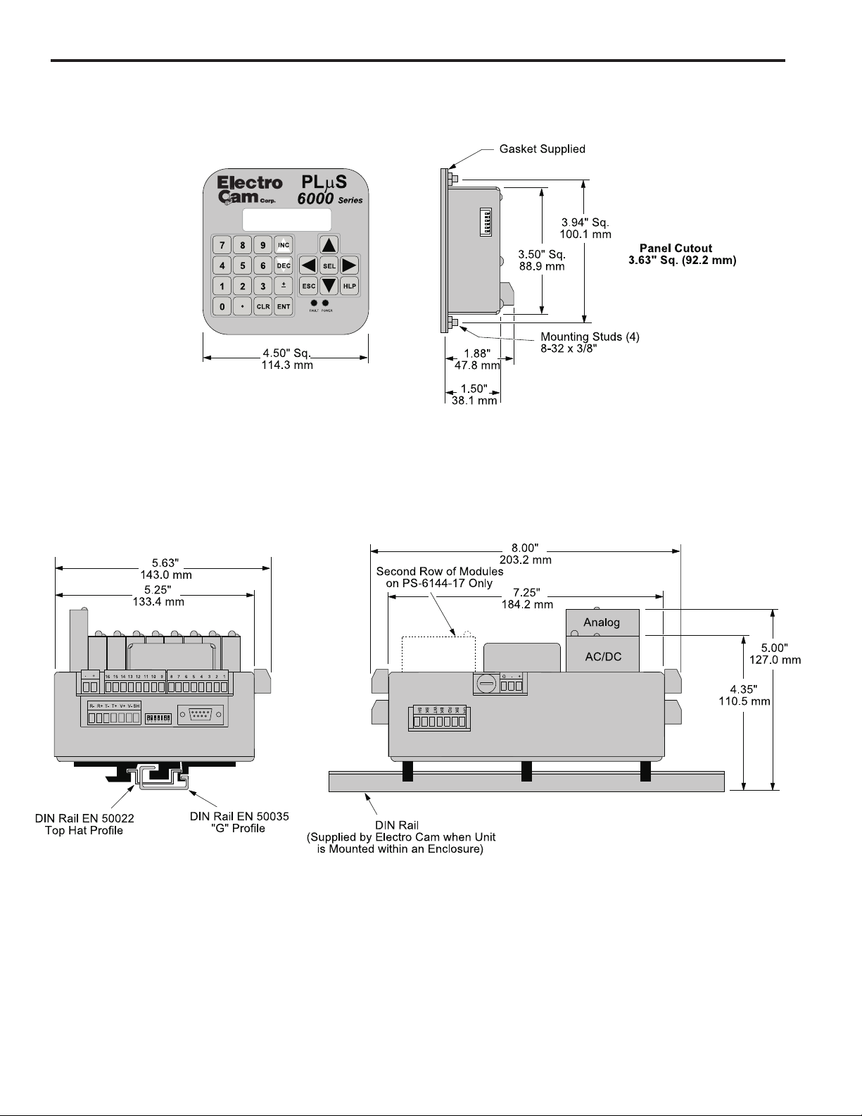
Mounting Dimensions
Figure 4—Mounting Dimensions
PGM:1 RPM:1500
MENU< POS: 180
2-2 Installation & Wiring
Page 11
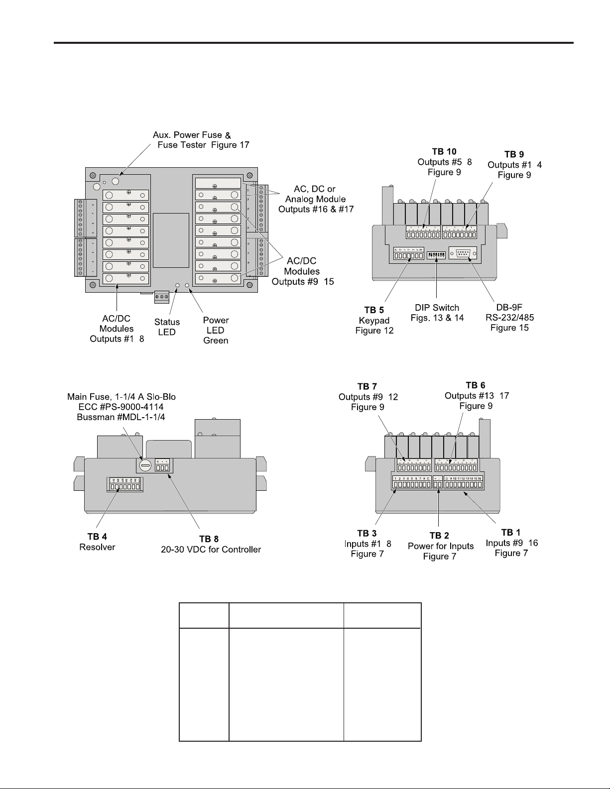
Terminals & Components—PS-6244-24-M17
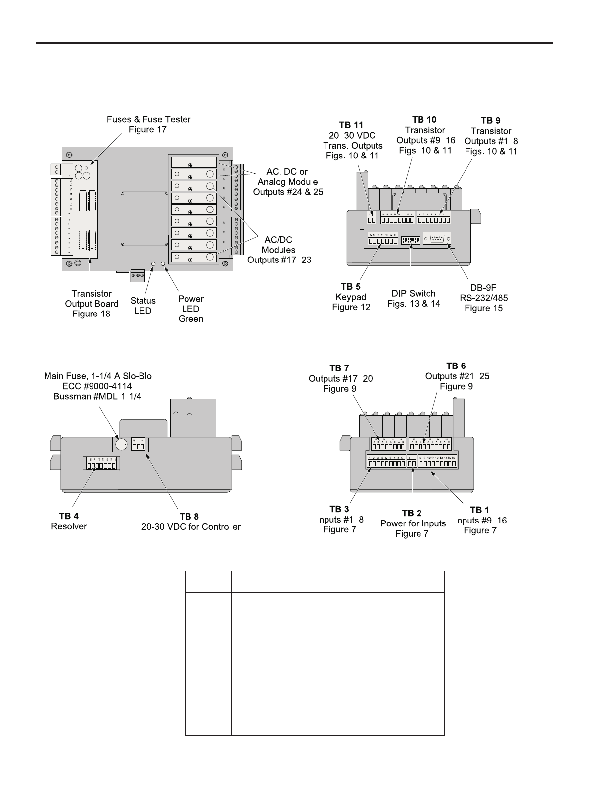
Figure 5—PS-6244-24-M17 Terminals & Components
Top View
-
Yellow
Front View
Left Side View
-
-
-
Right Side View
-
-
-
Terminal Block Details
Terminal
Block Function ECC Part #
TB 1 Inputs #9–16 PS-9006-0024
TB 2 Auxiliary power output PS-9006-0018
TB 3 Inputs #1–8 PS-9006-0023
TB 4 Encoder connector PS-9006-0032
TB 5 Keypad connector PS-9006-0029
TB 6 Module outputs #13-17 PS-9006-0031
TB 7 Module outputs #9-12 PS-9006-0030
TB 8 Power for controller PS-9006-0026
TB 9 Module outputs #1-4 PS-9006-0033
TB 10 Module outputs #5-8 PS-9006-0034
1
Keyed to prevent accidental insertion into wrong sockets.
-
1
2-3 Installation & Wiring
Page 12
Terminals & Components—PS-6244-24-X16M09
Figure 6—PS-6244-24-X16M09 Terminals & Components
Top View
Yellow
Front View
Left Side View
-
-
-
-
Right Side View
-
-
2-4 Installation & Wiring
-
Terminal Block Details
Terminal
Block Function ECC Part #
TB 1 Inputs #9–16 PS-9006-0024
TB 2 Auxiliary power output PS-9006-0018
TB 3 Inputs #1–8 PS-9006-0023
TB 4 Encoder connector PS-9006-0032
TB 5 Keypad connector PS-9006-0029
TB 6 Module outputs #21–25 PS-9006-0028
TB 7 Module outputs #17–20 PS-9006-0027
TB 8 Power for controller PS-9006-0026
TB 9 Transistor outputs #1–8, sinking PS-9006-0019
TB 10 Transistor outputs #9–16, sinking PS-9006-0020
TB 11 Power for transistor outputs PS-9006-0017
1
Keyed to prevent accidental insertion into wrong sockets.
Transistor outputs #1–8, sourcing PS-9006-0021
Transistor outputs #9–16, sourcing PS-9006-0022
-
1
Page 13

Controller Input Wiring
Input Terminals Hardware inputs can be used to select a program of setpoints, disable keypads, accept
sensor signals, or clear the shift register. The 16 inputs on the PS-6244 are arranged
on two terminal strips, TB 1 and TB 3, as shown in Figure 7. Each input is optically
isolated and can be powered from an external DC power source or the Auxiliary Power
terminals located on TB 2.
Sinking or Sourcing Each terminal strip TB 1 and TB 3 can be wired to accept sinking or sourcing input
signals, but all eight inputs on that strip will require the same type of signal. Many types
of hardware can drive these inputs, including mechanical switches, relay contacts, DC
3-wire sensors, solid state DC output modules, and PLC DC outputs. 2-wire DC sensors can also be used, but may require a load resistor in parallel with the input. Typical
wiring diagrams are shown in Figure 7.
Input Functions Following are the input terminals and their corresponding functions:
Channel Enable (1-8)
These terminals accept signals from sensors or from PLC’s. Each output channel on
the 6244 can be ANDed with any one of these inputs so that the output is enabled only
when a signal is present on the input terminal.
Program Select (9-13)
The on/off status of these terminals selects which program of setpoints is controlling
the outputs. Binary, BCD, or Gray Code formats can drive these terminals as shown in
Figure 8. Although standard controllers can store up to 48 programs, not all of these
programs can be selected through the Program Select terminals.
When all program select inputs are off, the “Default” program will become active as
programmed through DEFAULT PROGRAM function.
Shift Register Clear (14)
A signal on this terminal will completely clear the shift register for all output channels.
Keypad Disable (15)
When energized, this terminal disables any keypads connected to the controller. If the
controller will be used without any keypads, jumper this terminal so that it is always
energized.
Shift Register Input (16)
The leading edge of a signal on this terminal sets a bit in the shift register. See SHIFT
REGISTER ANDING for details.
2-5 Installation & Wiring
Page 14
Controller Input Wiring (cont’d)
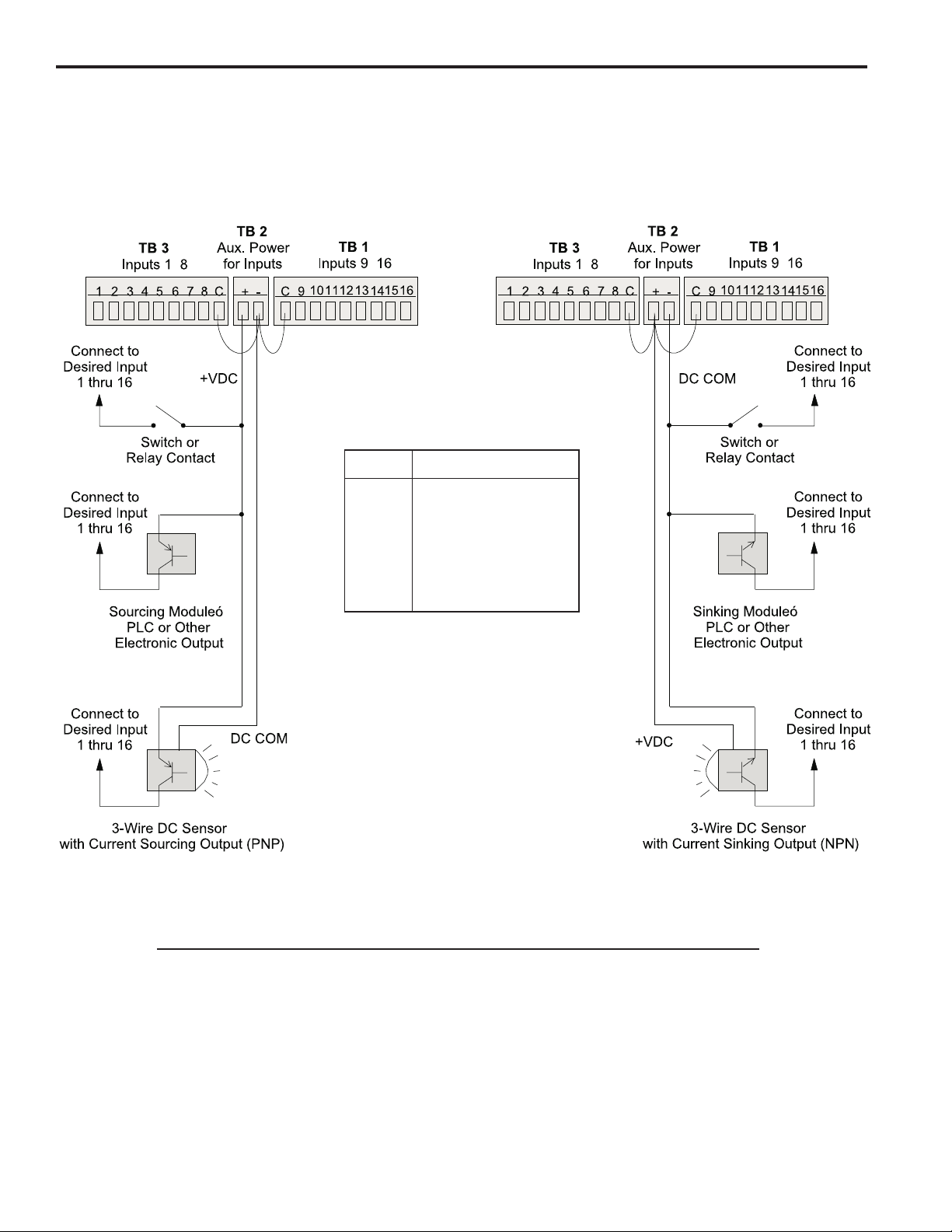
Figure 7—Controller Input Wiring (See Figures 5 & 6 for Terminal Block Locations)
Sourcing Devices
(+VDC is being switched)
-
-
Term. Function
1-8 Channel Enable
9-13 Program Select
14 Shift Register Clear
15 Keypad Disable
16 Shift Register Input
Sinking Devices
(DC common is being switched)
-
-
Input Wiring Guidelines
• Voltage from TB 2 will be the same as the voltage supplied to the controller.
• Each input powered from TB 2 will draw 11 mA at 24 VDC. TB 2 is fused at 1/4 amp.
• Inputs will operate with voltages from 10 to 30 VDC.
• An external power supply can be used instead of TB 2 to power inputs.
• A combination of mechanical and solid state devices can be used.
• TB 1 can be wired for sourcing while TB 3 is wired for sinking, and vice versa.
2-6 Installation & Wiring
Page 15

Controller Input Wiring (cont’d)
Figure 8—Program Select Terminals for Various Formats
BCD Program Select Table
The BCD format allows standard 1- or 2-digit BCD switches
to operate the program select inputs. PLC’s can also
output values in BCD. The program number selected can
be calculated by adding up the values associated with
each of the input terminals that are on. For example, if
Input Terminals 9, 11 and 13 are on, Program 15 would be
active (10 + 4 + 1).
Please Note:
• Although the PS-6244 can store up to 48 programs, only
Programs 1 through 19 can be selected using BCD input.
A value larger than 19 will select Program 19.
• Only one of the normal four BCD digits for 10’s is used.
• 9 is the largest valid value for the units digit. A units
digit combination larger than 9 will set the units digit to 9.
Binary Program Select Table
The binary format is convenient for PLC program select
output signals. The program number selected can be
calculated by adding up the values associated with each
of the input terminals that are on. For example, if input
terminals 9, 11 and 13 are on, program number 21 would
be active (16 + 4 + 1).
Please Note:
• Although the PS-6244 can store up to 48 programs, only
Programs 1 through 31 can be selected using binary
input. A value larger than 31 will select Program 31.
Gray Code Select Table
Input
Term: 13 12 11 10 9
Value: 10 8 4 2 1
PGM
Default 0 0 0 0 0
100001
200010
300011
400100
500101
600110
700111
801000
901001
Input
Term: 13 12 11 10 9
Value: 16 8 4 2 1
PGM
Default 0 0 0 0 0
1 00001
2 00010
3 00011
4 00100
5 00101
6 00110
7 00111
8 01000
9 01001
10 01010
11 01011
12 01100
13 0 1 1 0 1
14 01110
15 01111
UNITS10's 10'sUNITS
Input
Term: 13 12 11 10 9
Value: 10 8 4 2 1
PGM
10 10000
11 10001
12 10010
13 1 0 0 1 1
14 10100
15 10101
16 10110
17 10111
18 11000
19 11001
Input
Term: 13 12 11 10 9
Value: 16 8 4 2 1
PGM
16 1 0 0 0 0
17 10001
18 10010
19 10011
20 10100
21 10101
22 10110
23 10111
24 11000
25 11001
26 11010
27 11011
28 11100
29 1 1 1 0 1
30 11110
31 11111
Electro Cam 8-position Gray Code selector switches are
available as accessories for PLuS controls.
Please Note:
• Although the PS-6244 can store up to 48 programs, only
Programs 1 through 31 can be selected using gray code
input. A value larger than 31 will select Program 31.
Input MSB LSB
Term: 13 12 11 10 9
PGM
Default 0 0 0 0 0
100001
200011
300010
400110
500111
600101
700100
801100
901101
10 0 1 1 1 1
11 0 1 1 1 0
12 0 1 0 1 0
13 0 1 0 1 1
14 0 1 0 0 1
15 0 1 0 0 0
Input
Term: 13 12 11 10 9
PGM
16 11000
17 11001
18 11011
19 11010
20 11110
21 11111
22 11101
23 11100
24 10100
25 10101
26 10111
27 10110
28 10010
29 10011
30 10001
31 10000
MSB LSB
2-7 Installation & Wiring
Page 16

Output Wiring
Output Types The outputs available depend on the PS-6244 Model:
Output Model Model
Type 6244-24-M17 6244-24-X16M09
Transistor None Outputs 1-16
AC/DC/RR Modules Only Outputs 1-15 Outputs 17-23
AC/DC/RR or Analog Modules Output 16 Output 24
Analog Modules Only Output 17 Output 25
The load device to be driven must match the output type.
Power Output Modules Output modules can directly switch inductive loads and resistive loads that require more
current or voltage than the transistor outputs can supply. The modules do not supply
the power for the load; they simply switch it. Each output module has two dedicated
terminals and therefore does not share any common signal with the other modules.
This allows AC and DC modules to be mixed on the same control. DC modules can be
wired to sink or source as shown in Figure 9.
Analog Output Modules Analog output modules generate signals that are proportional to the encoder RPM.
They can be used only in the output positions shown above. Either a 0-10 Vdc or 4-20
mA analog module can be used in either module position. ANALOG QTY must be
programmed for the number of analog modules installed. An external power supply is
not needed because the analog modules get the power they source from the controller.
The analog output signal is completely isolated.
Transistor Outputs PS-6244-25 models include 16 transistor outputs to drive the electronic input circuits of
other control devices. The outputs are limited to 30 Vdc, 50 mA each and should not be
used to control inductive devices such as solenoids, solenoid valves or relays.
The control can be ordered with either sinking or sourcing transistor outputs. Both types
require a 10-30 VDC power supply connected to TB 11 to drive the transistor output
circuitry. The transistor output fuse will blow if the power supply polarity is incorrect, but
the circuitry will not be damaged. See Figs. 17 & 18 for fuse and transistor chip replacement.
Sinking transistor outputs (N16 controls, Figure 10) conduct to the negative terminal of TB 11. Therefore the common for TB 11 and the load must be electrically the
same. This may require connecting commons together if the power supplied to TB 11 is
not also the load power supply. Electronic counters/ratemeters often fall into this category. The power supply that powers the load does not have to be the same voltage as
the transistor power supplied to TB 11.
Sourcing transistor outputs (P16 controls, Figure 11) conduct to the positive power
terminal of TB 11. The load is therefore powered from the same supply that is providing
the transistor power.
2-8 Installation & Wiring
Page 17
Output Wiring (cont’ d)
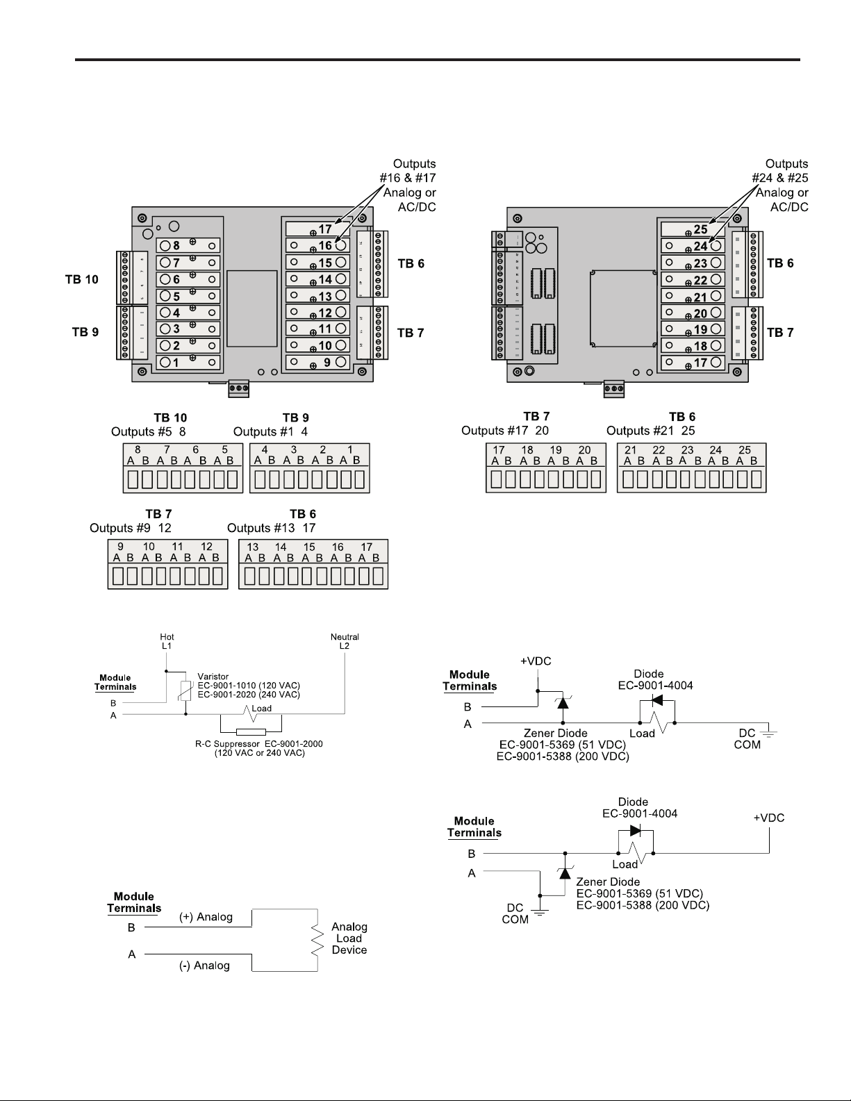
Figure 9—Wiring for Output Modules
PS-6244-24-M17
-
-
PS-6244-24-X16M09
-
-
--
-
-
AC Output
• When other switching devices are in series or parallel with the AC output
module, connect a varistor (MOV) across the terminals to prevent
module damage from inductive voltage spikes.
• Output modules act like switches; they do not supply power to loads.
Analog Output
• Analog output modules source the analog signal.
• No external supply is required.
• Analog output signals are isolated.
DC Output
Sourcing
Sinking
• Suppress spikes in inductive DC loads with one of the following
methods:
Connect a zener diode across the terminals. Turn off time will not be
significantly affected. Voltage rating of diode must be greater than the
normal circuit voltage. 50 VDC Zener, #EC-9001-5369; 200 VDC
Zener, #EC-9001-5388.
Connect a reverse-biased diode across the load. This will increase the
turn off time of the load. #EC-9001-4004.
2-9 Installation & Wiring
Page 18
Output Wiring (cont’ d)
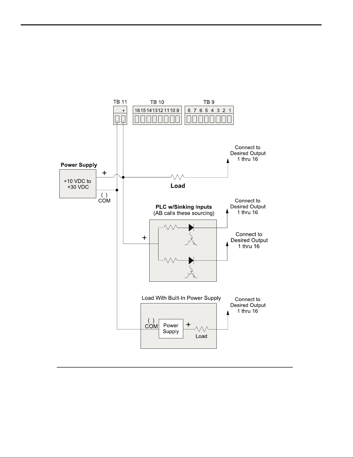
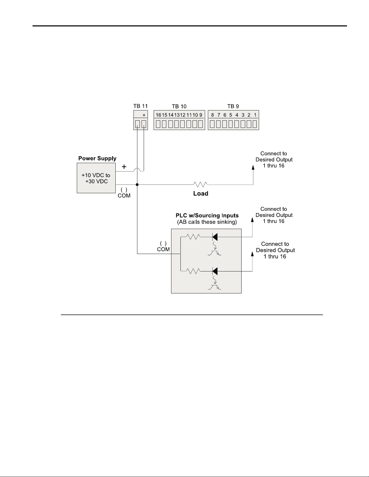
Figure 10—Wiring for Sinking Transistor Outputs (See Figure 6 for Terminal Block Locations)
Model PS-6244-24-N16M09
-
Please Note:
-
-
• Outputs are rated at 30 VDC, 50 mA.
• Transistor outputs should not be used to switch inductive devices such as solenoids or
relays.
• Sinking outputs conduct to the negative terminal of TB 11 when “on.”
• The power supply shown in “Load with Built-In Power Supply” does not have to be the same
voltage as the power supply connected to TB 11.
2-10 Installation & Wiring
Page 19
Output Wiring (cont’ d)
Figure 11—Wiring for Sourcing Transistor Outputs (See Figure 6 for Terminal Block Locations)
Model PS-6244-24-P16M09
-
-
-
Please Note:
• Outputs are rated at 30 VDC, 50 mA.
• Transistor outputs should not be used to switch inductive devices such as solenoids or relays.
• Sourcing outputs conduct to the positive terminal of TB 11 when “on.”
2-11 Installation & Wiring
Page 20

Keypad Wiring
Number of Keypads One or two keypads may be connected to a PS-6244 controller as shown in Figure 12.
See Figure 14 for possible system configurations.
Programming Enable The wiring connector on the back of each keypad includes terminals to select Operator
or Master level programming for that keypad. These terminals can be temporarily
jumpered during set-up to allow entry of programming access codes, or they can be
switched with a variety of devices including mechanical switches, relay contacts, and
PLC DC outputs. See ENABLE CODES in the programming section for details on programming access.
If a solid state device will be activating the Programming Enable terminals, that device
will determine whether sourcing or sinking wiring should be used. For mechanical devices such as jumpers or key switches, either sourcing or sinking wiring may be used.
Figure 12—Keypad Wiring
Keypad Connector
on Controller
-
Wh Bk Gn
Bk
Rd Bk
Programming Enable, Sourcing
Keypad
Terminal Block
Keypad
Terminal Block
--
Bk Wh Bk Gn
Rd Bk
Programming Enable, Sinking
-
-
Bk
Wh Bk
Rd Bk
Gn
2-12 Installation & Wiring
Page 21

DIP Switch Configurations
DIP Switches Each keypad and controller has a DIP switch as shown in Figure 13. For convenience,
set the DIP switches correctly before mounting the units in a panel.
Keypad Settings The address and termination settings on the keypad DIP switch apply to the RS-485
network that connects it to the controller. See Figure 14 for guidelines and sample
settings.
Controller Settings The address settings on the controller DIP switch apply to a network connecting the
controller to a PLC or other system host. When the DIP switch is set to zero, the default
address programmed through the COMMUNICATIONS function takes affect. Whereas
the DIP switches can set a maximum address of “7”, the COMMUNICATIONS function
can establish much higher address numbers. These settings are not related to com-
munications with the keypads.
Two sets of termination switches are included on the controller. One set establishes the
termination value for an RS-485 network connecting the controller to a PLC or other
system host. It does not apply to an RS-232 network. The other termination switches
apply to the keypad network. See Figure 14 for guidelines and sample settings.
Figure 13—DIP Switches and Related Communications Networks
NOTE: Both termination switches in a pair must be in the same position.
2-13 Installation & Wiring
Page 22

DIP Switch Configurations (cont’d)
Figure 14—DIP Switch Settings for Typical Systems
One Keypad
Two Keypads, Controller on End
Two Keypads, Controller in Middle
DIP Switch Guidelines
Termination: • Termination must be “on” for devices on each end of the chain.
• Termination must be “off” for devices in the middle of the chain.
• Both termination switches in a pair must be in the same position.
Address: • Keypad addresses must be assigned starting with “0” and increasing sequentially.
• The physical location of a keypad in the chain has no relationship to its address.
• During initial programming, the KEYBOARD QTY function must be used to enter the
number of keypads in the chain. KEYBOARD QTY can be accessed only through the
keypad whose address is “0.”
2-14 Installation & Wiring
Page 23

Communications Wiring
DB-9F Port Serial communication to a PLC or other system host is provided through a DB-9 female
connector as shown in Figures 5 & 6. This connector can be wired for RS-232 or RS485 communications.
RS-485 RS-485 can be used for “multi-drop” networks where more than one controller could be
connected to the system host.
RS-232 RS-232 can connect only a single PS-6244 to a system host.
RS-232/485 Selection Use the COMMUNICATIONS function to select RS-232 or RS-485 communications.
Figure 15—Communications Wiring
DB-9 Female Connector on Controller
(See Figures 5 & 6 for Location)
RS-232 Cable Wiring
DB-25 (Host) to DB-9F (PS-6244)
RS-232 Cable Wiring
DB-9 (Host) to DB-9F (PS-6244)
2-15 Installation & Wiring
Page 24

Encoder Wiring
General Information Choose a mounting location for the encoder that allows convenient mechanical con-
nection of the encoder shaft to the machine. The encoder is normally driven at a 1:1
ratio to machine cycles, but this is not true in all applications. Commonly used methods
for driving the encoder shaft include flexible couplings, timing belts and pulleys, chains,
and sprockets. Insure that the coupling method used is tight enough to minimize backlash without placing excessive side load on the encoder shaft.
If possible, select a location that shelters the encoder from accidental mechanical abuse,
lubricants, wash down chemicals or any other liquids.
Encoder Wiring Use shielded cable for wiring the encoder to the PS-6244 controller.
Figure 16—Encoder Connector Wiring
10-Pin Weidmiller TB4
654321
7
Pin Connection
1 +ENC
2 VREF
3A
4–A
5B
6–B
7Z
8–Z
9 COM
10 Shield
G-+
WX
ñ+Y
Z
S
98
10
2-16 Installation & Wiring
TB4 is EC part# PS-9006-0032.
It is keyed to prevent accidental
insertion into the wrong sockets.
Page 25

Fuse Tester & Fuse Replacement
Fuse Tester Figure 17 shows the location of a fuse test socket and LED which can be used to test
TR5 style fuses. PS-6244 controllers are shipped with a spare 4A fuse mounted in the
test socket.
Figure 17—TR5 Fuse Tester and Fuse Locations
PS-6244-24-M17 PS-6244-24-X16M09
Replacement TR5 Fuse Part Numbers
Rating Function ECC Part # Wickmann Part #
250 mA Power for Inputs (TB 2) PS-9005-0250 1937-035
1 A Power for Transistor Outputs (TB 11) PS-9005-0001 19370
4 A Fuse for Output Modules PS-9005-0004 19370-K
2-17 Installation & Wiring
Page 26

Output T ransistor Replacement
Check Fuse First If all of the transistor outputs fail to work, check the 1A fuse shown in Figures 17 & 18.
Also check to be sure that a 10–30 VDC power supply is connected to TB 11, Figure 6.
Correct Problems Chips will most likely be damaged by one of two events:
• A short circuit connected to one of the transistor outputs.
• A load exceeding 50 mA connected to one of the transistor outputs.
Before replacing a transistor output chip, fix the problem that damaged it.
Proper Placement When replacing a chip, be sure that all of the pins are properly seated in the socket.
Position the notch on the end of the chip as shown below.
Figure 18—Transistor Chip Replacement
TB 11
TB 10
TB 9
PS-6244-24-N16M09
Sinking Outputs
-
16 15 14 13 12 11 10 9
8 7 6 5 4 3 2 1
1A Fuse for
Transistor Outputs—
If blown, no transistor
outputs will work.
See Figure 17
for testing.
Empty
Socket Holes (2)
Position Notches
Like This
Jumper Block & Chip
For Outputs 9–16
• Jumper block
does not normally
need replacement.
Jumper Block & Chip
For Outputs 1–8
• Jumper block
does not normally
need replacement.
TB 11
TB 10
TB 9
PS-6244-24-P16M09
Sourcing Outputs
-
16 15 14 13 12 11 10 9
8 7 6 5 4 3 2 1
1A Fuse for
Transistor Outputs—
If blown, no transistor
outputs will work.
See Figure 17
for testing.
Chips for
Outputs 9–16
• Replace 2580 first.
• Replace 2803A if
that doesn’t work.
Position Notches
Like This
Chips for
Outputs 1–8
• Replace 2580 first.
• Replace 2803A if
that doesn’t work.
2-18 Installation & Wiring
Replacement Part Numbers
Description ECC Part #
UDN 2580 PS-9011-2580
ULN 2803A PS-9011-2803
DIP Jumper Block PS-9006-0015
Page 27

Motion Detection
l
t
Menu Path MAIN SCREEN to SETUP MENU to MOTION DETECT
Background Motion Detection establishes one or two “Motion Levels,” or speed ranges, with low
and high RPM values. These two ranges are independent of each other.
Using the MOTION ANDING screen, each output channel can be ANDed with either
Motion Level. ANDed outputs will be enabled only when the encoder speed is within the
specified speed range. Output channels that are not ANDed will be “on” whenever the
machine position is within their programmed setpoints, regardless of machine speed.
One use of Motion Levels and Motion ANDing is to turn off devices such as glue guns if
the machine stops or jams.
Screen The Motion Detection screen displays the Motion Level, the Low RPM, and the High
RPM.
MOTION LEVEL: 1
LO: 30 HI: 1500
Low RPM setpoint
Programming Use the numeric keys and ENT to change values for Motion Level, Low RPM, and High
RPM.
Motion Detector An output channel can be used as a motion detector by programming it to be on at “1”
and off at “1,” and then ANDing it with the desired Motion Level. This will turn the output
on constantly as long as the machine speed is within the specified Motion Level range.
See Also MOTION ANDING
Motion detection leve
High RPM setpoint
Offset
Menu Path MAIN SCREEN to SETUP MENU to OFFSET
Purpose This screen allows the encoder position to be set to zero at the desired machine posi-
tion, eliminating the need to mechanically adjust the encoder shaft coupling to the machine.
Output Group
GRP:1< POS: 0
ABS: 132
Group Position = Shaft Position + ABS Offse
Absolute Offset Value for this Group
Position Setup In order to set the Position to match the machine position, simply stop the machine at a
known position and enter the desired Position value. For example, jog the machine to a
position at the start of a new cycle, then set the Position to “0.”
Absolute Offset When you modify the Position, the Absolute Offset will change to the following number:
(Previous Absolute Offset) + (Change in Position)
• The Change in Position will be negative if the new position is less than the original
position, and will thus be subtracted from the Previous Absolute Offset.
Example: Absolute Offset is zero, and the machine is jogged to the start of a new cycle,
where the Position is 150. Using the keypad, the Position is reset to zero, for a change
in Position of (–150). The new Absolute Offset is thus zero minus 150. Since the model
of encoder used in this example shows positions from zero to 1000, the 150 is subtracted from 1000, resulting in an Absolute Position of 850.
Absolute Offset is intended to be used for "archival purposes", in case you lose correct
machine position and need to set the machine back up. Absolute Offset can be modified using the numeric keypad.
3-15 Programming
Page 28

Output Status
)
s
Menu Path MAIN SCREEN to SETUP MENU to I/O STATUS to OUTPUT
STATUS
Purpose This screen shows the On/Off state of the output channels.
Both Models, Outputs 1-8
12345678 OUTPUT
01001001 1-8<
Output On/Off Status (O=Off, 1=On)
PS-6344-17, Outputs 9-17
901234567 OUTPUT
0100100AA 9-17<
Analog Modules shown with "A"
PS-6344-25, Outputs 9-25
90123456 OUTPUT
01001000 9-16<
789012345 OUTPUT
0100100AA 17-25<
Output Numbers (1-8)
Output Numbers (9-17)
Output Numbers (9-16)
Output Numbers (17-25
Analog Modules shown with "A"
If any output positions have been programmed as analog outputs, the On/Off status will
show “A” instead of “0” or “1.”
Selecting Outputs To change the set of outputs displayed, press the SEL key.
Password
Menu Path MAIN SCREEN PASSWORD
This screen provides an area to enter a password. It also shows the current programming access level and the status of the Programming Enable terminals on the back of
the keypad, Figure 12.
PASSWORD:****<
LEV:NONE INP:OFF
Current programming level (hardware or software)
Enable Levels There are three programming access levels; OPERATOR, SETUP, and MASTER. See
Figure 21 for a summary of the programming functions available to the different levels.
The codes that correspond to each level are established in the ENABLE CODES screen.
Entering a Password Enter a password through the numeric keypad followed by ENT. As you press the
number keys, the asterisks will be replaced by dashes. If you make a mistake, press
CLR to erase the last key you pushed.
Password entry area
Keypad programming terminal input statu
3-16 Programming
Page 29

e
Password (Cont'd)
F
If you enter a password that has been programmed through ENABLE CODES, the
keypad will function at the corresponding programming level.
If either of the programming enable terminals on the back of the keypad is active when
a password is entered, the programming level will be whichever is greater.
PASSWORD:--**<
LEV:NONE INP:OFF
PASSWORD:****<
LEV:MAS INP:OFF
Enable level shown if number matches programmed password valu
Clearing a Password When programming operations are completed, enter a password value of “0,” then ENT
to clear the enable level.
If a keypad is left unattended with an active password, the access code will clear after
five minutes of keypad inactivity and the keypad will revert to the “Normal Display”
mode shown in Figure 21.
See Also ENABLE CODE
Dashes replace asterisks as numbers are entered
Dashes change back to asterisks with ENT
Per Channel Enable
Menu Path MAIN SCREEN to CONFIG MENU to PGM ENABLES to PER
CHN ENABLE
Purpose This screen is used to enable Operator Level access to individual output channels.
CHN ENABLE is used in conjunction with the ENABLE OPTIONS screen to assign
Operator Level access to selected programming functions.
CHN: 12<
CHN ENABLE: ON
Channel Select Press the INC/DEC keys, or use the numeric keys and ENT.
Enable Toggle Press the SEL key to toggle the enable ON or OFF.
See Also ENABLE OPTIONS
Channel number
Per channel enable: ON/OF
(Toggle with SEL key)
3-17 Programming
Page 30

Program Copy
L
Menu Path MAIN SCREEN to SETUP MENU to PGM COPY
Purpose Program Copy allows you to copy all of the channels and setpoints from one program to
another. It is often easier to copy an existing program and modify it, than to enter a new
program from scratch.
Screens The Program Copy function consists of four screens:
SRC PROGRAM:---<
DST PROGRAM:---<
DST PROGRAM: 6<
EXECUTE<
DST PROGRAM: 6
COMPLETE<
Programming Use the numeric keys and SEL to enter program numbers.
During programming, the cursor keys allow you to move between the Source and Destination screens to allow you to change values before selecting EXECUTE.
Program to be copied from
Destination to be copied to
Move cursor to EXECUTE, then press SE
to copy program
COMPLETE indicates program
successfully copied
Program Select Mode
Menu Path MAIN SCREEN to CONFIG MENU HARDWARE to PGM SEL
MODE
Purpose This screen allows you to specify the format for the hardware Program Select inputs on
terminals 9 through 13 of Terminal Block 11, Figure 7.
PROGRAM SELECT
MODE: BIN<
The Program Select inputs can operate in Binary, BCD, or Gray Code formats as shown
in Figure 8.
Use the SEL key to toggle the input format.
If the input signals controlling program selection are lost due to a malfunction,
the Default Program will activate. To prevent sudden changes in machinery operation that may damage equipment or injure personnel, program the Default
Program with settings that will not cause harm in the event of sudden activation.
See Also DEFAULT PROGRAM
Hardware Program Select Format: BIN = Binary,
GRAY = Gray Code, BCD = Binary Coded Decimal
3-18 Programming
Page 31

Pulse Copy
Menu Path MAIN SCREEN to SETUP MENU to PULSE COPY
Purpose Pulse Copy allows you to program a series, or “train” of pulses into a channel without
having to enter the On and Off setpoints for each pulse. The Pulse Copy function prompts
you for the beginning and ending setpoints for the pulse train; the number of pulses in
the train; and the duration of a pulse. Pulse Copy then divides the designated portion of
the encoder cycle into the specified number of pulses, evenly dividing the unused portion of the segment between the pulses.
Screens The Pulse Copy function consists of eight screens:
PROGRAM:---<
CHANNEL:---<
ON:---<
OFF:---<
COUNT---<
DURATION:---<
DURATION: 35
EXECUTE<
Program to add pulses to;
Enter number, then SEL to go to next screen
Channel to add pulses to;
Enter number, then SEL to go to next screen
"On" time of leading edge of first pulse;
Enter number, then ENT & SEL to go to next screen
"Off" time of trailing edge of last pulse;
Enter number, then ENT & SEL to go to next screen
Total number of pulses to be added;
Enter number, then ENT & SEL to go to next screen
Duration of each pulse added;
Enter number, then ENT & SEL to go to next screen
Move cursor to EXECUTE, then press SEL to
generate pulses. To review values before executing,
move cursor to top row and press SEL as needed
DURATION: 35
COMPLETE<
Example Generate a train of pulses for a Krones Label Check Unit as follows:
Pulse On Off
1050
2 100 150
3 200 250
4 300 350
5 400 450
6 500 550
7 600 650
8 700 750
9 800 850
10 900 950
COMPLETE indicates pulses have been generated
3-19 Programming
Page 32

Pulse Copy (cont’d)
3
Each pulse is 50 increments wide, separated from the next pulse by 50 increments.
Program PULSE COPY as follows:
PROGRAM:---<
CHANNEL:---<
ON: 0<
OFF:950<
COUNT 10<
DURATION: 50<
DURATION: 50
EXECUTE<
Program to add pulses to;
Enter number, then SEL to go to next screen
Channel to add pulses to;
Enter number, then SEL to go to next screen
"On" time of leading edge of first pulse;
Enter 0, then ENT & SEL to go to next screen
"Off" time of trailing edge of last pulse;
Enter 950, then ENT & SEL to go to next screen
Total number of pulses to be added;
Enter 10, then ENT & SEL to go to next screen
Duration of each pulse added;
Enter 50, then ENT & SEL to go to next screen
Move cursor to EXECUTE, then press SEL to
generate pulses.
DURATION: 35
COMPLETE<
Go to SETPOINTS to confirm the pulse train:
<-P-> CH: 1 <EDG
ON: 0 OF: 50
COMPLETE indicates pulses have been generated
Move cursor to OF and use arrow keys to
review pulse setpoints
Rate Setup
Menu Path MAIN SCREEN to CONFIG MENU to DISPLAY
RATE SETUP
Purpose The Rate Setup function allows you to configure the RPM display on the Main Screen.
The Main Screen can display the encoder speed in units of Revolutions Per Minute
(RPM), Bags Per Minute (BPM), or Cartons Per Minute (CPM). The encoder speed can
also be displayed as .5X, 1X, 2X, or 3X actual RPM.
Screen
MPY: 1< DP: 0
DIV: 1 RPM
Multiplier: 0 through 1091
Number of decimal points displayed: 0, 1, 2, or
Units: RPM, BPM, CPM, IPM
Divider: 1 through 63
3-20 Programming
Page 33

Rate Setup (Cont'd)
SCALE
FACTOR: 360<
Number of increments each revolution is broken into
RPM UPDATE
RATE: 1/S<
RPM Update Rate: How often RPM display on main
screen is updated; 1/Sec, 2/Sec, or 10/Sec.
Press the SEL key to toggle display mode or rate. Following is a chart summarizing the
relationships between encoder speed, units, and rate multiplier:
If And Then an Is
Units Rate Encoder Displayed
Are… Is… Speed Of… As…
RPM .5X 100 RPM 50 RPM
1X 100 RPM 100 RPM
2X 100 RPM 200 RPM
3X 100 RPM 300 RPM
BPM .5X 100 RPM 50 BPM
1X 100 RPM 100 BPM
2X 100 RPM 200 BPM
3X 100 RPM 300 BPM
CPM .5X 100 RPM 50 CPM
1X 100 RPM 100 CPM
2X 100 RPM 200 CPM
3X 100 RPM 300 CPM
RPM Update Rate
Menu Path MAIN SCREEN to CONFIG MENU to DISPLAY
RPM UPD RATE
Purpose The RPM Update Rate is how often the RPM display on the Main Screen is updated.
This rate can be programmed to be 1/Sec, 2/Sec, or 10/Sec.
Screen
Press the SEL key to toggle the selection.
Scale Factor
Menu Path MAIN SCREEN to CONFIG MENU to HARDWARE MENU SCALE
FACTOR
Purpose The Scale Factor screen displays the number of increments into which one encoder
revolution is divided. For the PS-6244 special unit, Scale Factor is fixed at 1000.
3-21 Programming
Page 34

Setpoint Use
g
y
l
s
Menu Path MAIN SCREEN to SETUP MENU to SYSTEM INFO SETPOINT
USE
Purpose This function displays the total number of setpoint On/Off pairs, or “pulses” available for
programming, and the number of pulses that have been programmed.
Screen
TOTAL: 1200
USED: 64
The number of setpoints shown as "Used" is the sum of all pulses that are programmed
into all channels of all programs. The "Total" value is the number of pulses that can be
stored in non-volatile EEPROM memory. The difference between the two numbers is
the number of pulses available for programming.
The number of pulses programmed into all channels of all programs cannot exceed the
value displayed as Total.
There are no values that can be changed in this screen.
Total number of pulses available for programmin
Number of pulses programmed into all channels
of all programs
Setpoints
Menu Path MAIN SCREEN to SETPOINTS
Screens When SETPOINTS is selected, a preliminary screen specifies the program whose
setpoints will be programmed.
PGM NUMBER: <
The active program is displayed, but any other program can be specified by using the
numeric keys or INC and DEC to choose a program, then pressing SEL to move to
setpoint programming.
Blank if only 1 pulse in channe
Channel
CH: 1 <EDG
ON: 90 OF: 270
ON setpoint
<-P-> indicates multiple pulses in channel
<-P-> CH:1<EDG
ON: 90 OF: 270
Channel to Edit Use the numeric keypad and ENT to select the channel to program.
• CHN 91 is a special channel used for shift register functions. See “Shift Register
ANDing” for details.
Program to view or modif
Pulse mode
OFF setpoint
Setpoint Values Use the left and right arrow keys to move between the On and Off setpoints.
• If a channel has more than one pulse, you may view the other pulses by pressing the
right cursor key when viewing the Off setpoint, or by pressing the left cursor key when
viewing the On setpoint.
• If a channel contains no pulses, the On and Off setpoints will be “0.”
• If a channel is always on, both the On and Off setpoints will be “1.”
CH:1 EDG
ON: 0< OF: 0
3-22 Programming
ON and OFF setpoints both 0 if no pulse
in channel. Both 1 if channel always ON
Page 35

Setpoints (cont’d)
Adding a Pulse You may add a new pulse to a channel by pressing the SEL key when the cursor points
to either the On or the Off setpoint.
CH:1 EDG
ON:---< OF:---
The display will change to show blank On and Off setpoints; the cursor will point to the
On setpoint. Enter the On setpoint through the numeric keypad, and then press the
ENT key or the right cursor to move to the Off setpoint. Enter the Off setpoint through
the numeric keypad and then press the ENT key.
Adding Multiple Pulses If On and Off setpoints for a pulse are visible on the screen and you press SEL to
program a new pulse, the original pulse will remain in the output channel. If the On or
Off setpoints you enter overlap an existing pulse in the channel, you will see an “Error:
Pulse Overlap” message.
To abort entering a pulse at any time, press ESC.
Changing Setpoints Change a setpoint value with the numeric keys followed by ENT, or with the INC and
DEC keys.
Pulse Modes The Pulse Mode controls how the INC and DEC keys modify setpoints. There are three
modes; EDG (edge), PUL (pulse), and CHN (channel.) You change the Pulse Mode by
pressing the SEL key when the cursor points to the Pulse Mode.
Enter ON setpoint, then ENT or right cursor to OF.
Enter OFF setpoint, then press ENT.
In EDG mode, the INC and DEC keys will affect the selected On or Off setpoint only.
In PUL mode, both On and Off setpoints will be incremented or decremented simulta-
neously.
In CHN mode, all On and Off setpoints for all pulses in the channel will be incremented
or decremented simultaneously.
Deleting a Pulse A pulse may be deleted by making On equal to Off, or vice versa. If there is more than
one pulse in the channel, the next pulse will appear in the On/Off setpoint area. If the
channel has no more pulses, the On and Off setpoint will both be zero.
Clearing a Channel To clear a channel of all pulses, enter a new pulse with On and Off setpoints of “0.”
Channel Always ON A channel may be programmed to be On for a full revolution (always On) by entering a
new pulse with both On and Off values equal to “1.”
Record Setpoints Photocopy the form inside of the back cover and use it to write down setpoints for each
program.
Shift Position
Menu Path MAIN SCREEN to SETUP MENU to SHIFT POSITION
Purpose The Shift Position is the point in the encoder revolution at which the shift register data
shifts. See Shift Register ANDing for details.
SHIFT POS: 850
Programming Use INC and DEC, or the numeric keys and ENT.
Position at which Shift Register will shift.
3-23 Programming
Page 36

Shift Register ANDing
Menu Path MAIN SCREEN to CONFIG MENU to CHN ANDING MENU SHFT
REG ANDING
Background The shift register is a form of electronic memory that sets a “bit” in the zero count of the
register when a signal is applied to Terminal 16, Fig. 7. Afterwards, each time the encoder passes the point programmed through SHIFT POSITION, the register “shifts” the
bit to the next higher count. The bit passes along the shift register until, on the 256th
shift, the bit is erased.
An output channel can be ANDed with any count in the shift register, so that the channel is enabled only when a bit appears in that count. In this way, output channels can be
enabled up to 255 revolutions after Terminal 16 is energized.
Zero Bit is Set
If Terminal 16 is
Energized Within
Channel 91 Window
Count:
1 2 3 4 253 254 255
0
Bit Shifts Up Once
Each Time Encoder
Passes Shift Position
Bit is Erased
On Last Shift
Output Channels
Can Be ANDed with Any
Shift Register Count
Programming This screen allows you to enter the output channel to ANDed with the shift register, and
the shift register count that will enable it.
CHN: 1
SHIFT COUNT: 0
Output Channel to be ANDed
Shift Count That Will Enable Output Channel
To select the output channel and the shift register count, use the numeric keys and
ENT, or use the INC and DEC keys.
• ANDing an output channel with Count “0” is the same as turning Shift Register
ANDing off. The shift register will have no affect on channel operation.
• Any number of output channels can be ANDed to a single shift register count.
• Shift Register ANDing, Input ANDing, and Motion ANDing can be combined for any
given output channel.
Input Window A bit is set in Position “0” of the shift register when Terminal 16 of TB 1, Figure 7, is
energized. A special channel, Channel 91, is provided to limit the portion of an encoder
revolution during which the signal will be accepted from Terminal 16. A “window” can
be programmed into Channel 91 so that a bit is set in the register only if Terminal 16
becomes energized within that window.
3-24 Programming
Page 37

Shift Register ANDing (cont’d)
Shift Position The point in the encoder revolution at which the register shifts data is programmed
through SHIFT POSITION. When programming Shift Position and the On/Off setpoints
for a channel, remember the following:
Don’t Place the Shift Position at the Start of a Pulse
When a pulse starts at the Shift Position, as
0
500
Shift
Position
220
Output
Channel
On at 220
Off at 290
Don’t Let Speed Comp Move a Pulse Onto the Shift Position
shown here, the pulse will be enabled as soon as
a bit is shifted into the programmed shift count.
Although the output will function normally on this
revolution, a small output spike may occur on the
following revolution as the bit is shifted to the
next shift count.
Machine at
“Zero” Speed
0
500
At “Zero” Speed in this example, the output turns on 100 increments after the Shift
Position. However, as the machine accelerates, speed compensation advances the
setpoints until they overlap the Shift Position. This may split the pulse between two
machine cycles. The portion of the pulse following the Shift Position may activate
during one cycle, while the portion ahead of the Shift Position may activate during
the following cycle.
Shift
Position
100
Output
Channel
On at 200
Off at 270
Machine at High RPM
Setpoints Advanced
By Speed Comp
0
500
Shift
Position
100
The Channel 91 Window is “edge sensitive” to the signal from Terminal 16. The leading
edge of the signal must appear in the window for a bit to be set in the register.
Shift Register Clear Energizing Terminal 14 on TB 1, Figure 7, clears all bits from the shift register immedi-
ately.
(continued)
3-25 Programming
Page 38

Shift Register ANDing (cont’d)
Edge Sensitivity of Channel 91 Window
(Channel 91 programmed “on” at 650, “off” at 750 in this example; Shift Position = 0)
Shift
Position
CHN 91
0
500
Terminal 16
Leading Edge
On Within Channel 91;
Bit Set at 0 In Register
Leading & Trailing Edges
Bit Set at 0 In Register
Shift
Position
0
500
Terminal 16
Within Channel 91;
Channel 91 Overlaps Shift Position—Not Recommended!
When Channel 91 overlaps the shift position as
shown here, two problems may occur.
One Product, Two Bits: Due to variations in conditions,
sensors sometimes generate more than one pulse for a
product. If the product sensor sends a pulse early in the
window, that pulse will shift when the encoder reaches
the shift position. If the sensor sends a second pulse for
the same product after the shift position, a second bit will
be set for the same product.
Inconsistent Timing: Some products may appear early
in the Channel 91 window, while others appear late. For
early products, a bit will be set, then immediately shifted
at the shift position. For late products, a bit will be set
after the shift position, and a full revolution will occur
before the bit shifts to 1.
In most applications, programming Channel 91 to
overlap the Shift Position will cause problems.
Shift
Position
CHN 91CHN 91
0
500
Terminal 16
Leading Edge
On Before Channel 91;
Bit Not Set
Channel 91
On at 900
Off at 100
Shift
Position
CHN 91
0
500
Terminal 16
Leading & Trailing Edges
Outside Channel 91;
Bit Not Set
First Bit Set
Shift Position
Second Bit Set
0
500
Software V ersion
Menu Path MAIN SCREEN to SETUP MENU to SYSTEM INFO to
SOFTWARE VERSION
Purpose The Software Version screen displays the revision number of the firmware contained
within the controller. This information may be useful if the unit needs to be returned for
service.
MAJOR REV:1.75
BASE REV:1.17
There are no values that can be changed in this screen.
3-26 Programming
Page 39

Speed Compensation
)
Menu Path MAIN SCREEN to SETUP MENU to SPEED COMP
Background Some devices such as hydraulic cylinders and glue guns require a fixed amount of time
to perform their function. As a machine speeds up, these devices need to be actuated
earlier in the cycle in order to complete their action at the required time. Speed compensation automatically advances the On/Off setpoints of specified output channel(s) as
the machine speeds up, maintaining proper synchronization at all speeds.
Speed Comp Units Speed compensation is programmed by entering the response time of the output de-
vice in milliseconds (.001 Sec). The output will always turn on this number of mSec
before the programmed On position is reached, and turn off this number of mSec before the programmed Off position is reached. As speed increases, the number of degrees of advance will automatically increase to maintain the number of mSec of advance.
Screen The speed compensation screen shows the Output Channel and the speed compensa-
tion value for that channel.
Output Channel
CH: 1<LE: 10.0
TE: 20.0
To change speed comp values, use the numeric keys or INC and DEC. You can enter
values of speed comp in milliseconds without using the decimal point: “12 ENT” will
result in a value of 12.0.
To change output channels, move the cursor to the channel number and enter a new
one. You may also INC or DEC the channel number.
Negative Speed Comp Negative values of speed compensation cause the output channel to lag its programmed
machine position by the specified number of mSec.
It is used when an input sensor is being gated, by the corresponding output channel,
into another control system (PLC, registration control, etc.) Sensor lag can cause an
object that is present at the correct position in the cycle to appear late. Negative speed
comp can retard the gate signal so the sensor and gate signals are in sync when the
object is in the correct position.
Since most sensors have very fast response times, negative speed comp is needed
only where the sensor is slow to respond or the machine speeds are high and sensor
timing is critical.
It may also be used if there is mechanical "wrap up" present in the machine being
controlled. Wrap up will cause machine elements to shift relative to each other as speed
increases. This situation may cause an event to happen later in the cycle as the machine goes faster.
Setting Negative Comp Press the +/- key after entering a number but before pressing ENT, or by decrement a
value below zero.
Leading edge compensation (10 msec shown
Trailing edge compensation (20 msec shown)
3-27 Programming
Page 40

Toggle RPM
Menu Path MAIN SCREEN to CONFIG MENU to DISPLAY MENU to
TOGGLE RPM
Purpose Toggle RPM is the encoder speed at which the Position display on the Main Screen will
disappear. At speeds below the Toggle RPM the Position display will be visible; at
speeds above the Toggle RPM the Position will not be shown.
TOGGLE
RPM: 50
This screen displays the Toggle RPM.
Toggle RPM: Position display on main screen
is not shown at speeds above Toggle RPM
3-28 Programming
Page 41

Controller Diagnostics
CAUTION
Status LED The red Status LED on the controller, Figures 5 & 6, blinks in various patterns to indi-
The controller cannot be repaired in the field. If a unit fails, do not disassemble it.
Return it to the factory for replacement.
cate the controller status.
Normal Operation
The Status LED blinks on and off rapidly.
Keypad Not Connected
If the controller is powered without a keypad connected, the LED blinking pattern will be
“off” for one second, followed by four quick “on” blinks.
Internal Errors
If the LED blinking pattern is “on” for a second, followed by one or more quick blinks
“off,” the controller is experiencing internal errors. The specific error is indicated by the
number of “off” blinks:
One “Off” Blink—Corrupt RAM
Two “Off” Blinks—Checksum error indicating EPROM corruption.
Three “Off” Blinks—System error.
Four “Off” Blinks—System error.
If any of the above four patterns occur, power cycle the control. If the pattern occurs
again, remove the controller from service and return it to the factory.
Five “Off” Blinks—Internal error; possibly noise problems.
Six “Off” Blinks—Internal error; possibly noise problems.
If either of these two patterns occur, check for loose connections and fix any obvious
noise problems. If the problem persists, remove the controller from service and return it
to the factory.
4-1 Troubleshooting
Page 42

Keypad Diagnostics
CAUTION
Keypad Fault LED If the Fault LED on the keypad lights, turn the controller off and back on. If the keypad
Keypad Diagnostics The 6400 Keypad includes a series of diagnostics that show the status of various key-
The keypad cannot be repaired in the field. If a unit fails, do not disassemble it.
Return it to the factory for replacement.
Fault LED does not go off, the keypad microprocessor has malfunctioned. Return the
keypad to the factory.
pad functions. To start the diagnostics, turn the controller off, then restart the controller
while pressing any key on the keypad.
Unique key ID# appears here when any key is pressed.
15 REV 1.00
CS:024B 07APR94
Keypad software revision #.
Keypad software revision date.
Keypad checksum.
FAULT LED
Fault LED blinks ON one second, OFF one second.
Press up or down arrow to return to menu.
PROGRAM ENABLE
1 = E1 jumpered; 2 = E2 jumpered.
Press up or down arrow to return to menu.
ADDRESS SWITCHES
COMM PORT
DISPLAY
KEYBOARD
Figure 22—Keypad Communications Port Test Setup
_
When the COMM PORT diagnostic is run with keypad terminals W,
X, Y, and Z jumpered as shown, a string of “plus” signs will scroll
across the display. When either jumper is removed, the scrolling will
stop.
Shows keypad DIP switch address setting.
Press up or down arrow to return to menu.
Tests communication.
Press up or down arrow to return to menu.
Complete character set scrolls across both lines.
Press up or down arrow to return to menu.
Displays unique key# for each key pressed.
Press hidden key on face below HLP key to exit.
4-2 Troubleshooting
Page 43

Encoder T roubleshooting
Encoder Type The encoder used with the PS-6244 controller is an incremental quadrature encoder.
The encoder sends three signals to the controller: A, B, and Z, as shown below in
Figure 23.
Failure Symptoms Most encoder failures or wiring problems will affect the POS (position) display. Some of
the possible symptoms are listed below:
Pins 1, 2, 3, 5, 9: Failure Before Startup
Position display remains at zero.
Failure During Operation
The display will freeze on the position at the time of circuit break. If the circuit is reconnected before power is turned off, the display will resume incrementing until the
zero pulse (Signal “Z”) is received, at which time the display will return to its programmed offset value.
Pin 7: Failure Before Startup
Position display remains at zero.
Failure During Operation
Operation will appear to be unaffected. However, errors in count values may accumulate, and on subsequent startup, the display will remain at zero.
Depending on the type and timing of encoder failure, the machine may continue
operating normally until it is turned off. On subsequent startup, the POS (position) display may be “frozen” at zero.
Figure 23—Quadrature Encoder Signals & Controller Pin Connections
10-Pin Weidmiller TB4
Pin Connection
1 +ENC
2 VREF
3A
4–A
5B
6–B
7Z
8–Z
9 COM
10 Shield
Signal
A
B
Z
Pulses
Function
Increments position; relationship with "B"
indicates direction.
Increments position; relationship with "A"
indicates direction.
Resets position to "0" once per revolution.
4-3 Troubleshooting
Page 44

General T roubleshooting
The controller and keypad cannot be repaired in the field. If a unit fails, do not
disassemble it. Return it to the factory for replacement.
Problem Possible Solution
Controller & keypad dead. 1. Check main fuse shown in Figs. 5 & 6.
2. Check power supply to controller.
Keypad dead, but controller 1. Check wiring between keypad and controller, Figure 12.
LED’s are on.
Keypad Fault LED “On” 1. Keypad microprocessor has malfunctioned. Turn the controller off and back on. If the
keypad Fault LED does not go off, return the keypad to the factory.
Menu operation Slow on 1. Check KEYBOARD QTY programming. If it is set for two keypads, but only one is
keypad display connected, menu operation will be very slow.
COMM FAILURE—HOST TO 1. This message may flash briefly on power-up under normal conditions.
KEYBOARD message 2. If the message persists, check keypad wiring connections at keypad and controller,
Figure 12.
3. Check DIP switch settings, Figures 13 & 14.
4. Be sure Input Terminal #15, Figure 7, is not energized.
Programming functions not 1. Programming not enabled. See Figure 12, and also ENABLE CODES for details.
accessible.
POS (position) frozen at “0” 1. Encoder or encoder wiring may have failed. Unplug cable at encoder and plug a
spare encoder into the cable. If this solves the problem replace the encoder on the
machine. If not, prepare a short encoder cable (Fig. 16), unplug the cable at the
controller, and plug the short cable with spare encoder into the controller. If this solves
the problem, replace the cable on the machine. See page 4-3 for more.
POS (position) moves opposite 1. Check INCREASING DIR for the correct direction of rotation.
to machine direction. 2. Check encoder wiring, Figure 16.
POS (position) does not 1. Verify that OFFSET is correct. Once set, the offset value should not change. If it
match machine position. does, check the encoder coupling to be sure it is not loose. Also see “Encoder Trouble-
shooting,” page 4-3. An intermittent encoder connection on controller pins 1, 2, 3, 5,
or 9 might cause POS to lag the actual encoder position until the next “zero” pulse
(“Z” signal) is received from the encoder.
Serial communications 1. Check COMMUNICATIONS programming to be sure type, baud rate, and address
not working are correctly set.
2. Be sure the DIP switches for the PLuS-to-host communications are set correctly as
shown in Figure 13.
3. Check communication cable wiring, Figure 2-15.
Outputs cycling regularly at 1. Check that the correct program number is active.
incorrect machine positions 2. Check the setpoints of the output(s) in question. Also check SPEED COMP settings.
3. Verify that OFFSET is correct.
Erratic Operation 1. Run the Watchdog Timer test described under MEMORY TESTS in the programming
section of this manual.
2. See “Encoder Troubleshooting,” page 4-3.
(continued)
4-4 Troubleshooting
Page 45

General T roubleshooting (cont’d)
Analog output not working. 1. Check that ANALOG QTY and ANALOG OUTPUT are programmed correctly.
2. Check that analog output module is located in the correct module position. See Figure 5 or 6.
3. Check correct wiring of analog output.
4. Verify that analog load device is within specifications for the analog module.
5. Try a different analog output module.
Some transistor outputs 1. Check that the correct program number is active.
are not working. 2. Use OUTPUT STATUS to see if the controller is activating the output(s) at the correct
position in the encoder revolution. If not, verify that the SETPOINTS are correctly
programmed. Other programming that may prevent an output from energizing includes MOTION ANDING, INPUT ANDING, and SHFT REG ANDING.
3. If OUTPUT STATUS shows the output is on, use a meter to see if the output terminal
is energized. If so, check the load device and its wiring. If not, go to Step 4.
4. Check the transistor array chips, Figure 17.
All transistor outputs 1. Check that the correct program number is active.
are not working. 2. Use OUTPUT STATUS to see if the controller is activating the output(s) at the correct
position in the encoder revolution. If not, verify that the SETPOINTS are correctly
programmed. Other programming that may prevent an output from energizing includes MOTION ANDING, INPUT ANDING, and SHFT REG ANDING.
3. If OUTPUT STATUS shows the output is on, use a meter to see if the output terminal
is energized. If so, check the load device and its wiring. If not, check the transistor
output fuse, Figure 18. Use the fuse tester built into the controller, Figure 17.
4. Check that 10-30 VDC power is connected to TB 11, Figure 10 & 11.
AC/DC module output 1. Check that correct program number is active.
not working. 2. Use OUTPUT STATUS to see if the controller is activating the output(s) at the correct
position in the encoder revolution. If not, verify that the SETPOINTS are correctly
programmed. Remember that AC/DC output modules are controlled by Channels 17
through 24. Other programming that may prevent an output from energizing includes
MOTION ANDING, INPUT ANDING, and SHFT REG ANDING.
3. If OUTPUT STATUS shows the output is on, but the LED on top of the module does
not light, try replacing the module.
4. If the LED on the module lights but the output terminal does not energize, check the
fuse built into the top of the module. Use the fuse tester built into the controller, Figure
17.
5. Check that load power is present in the circuit and correctly wired. Remember that
modules do not supply power to loads; they simply switch the load circuit on and off.
4-5 Troubleshooting
Page 46

Fuse Part Numbers
Fuse Description Mfct. Part # Electro Cam Part #
Main Fuse (Figs. 5 & 6) .........................1-1/4 Amp Slo-Blo Glass .... Bussman MDL-1-1/4 ....... PS-9000-4114
Module Fuse.......................................... 4 Amp TR-5........................ Wickmann 19370-K......... PS-9005-0004
Input Fuse (Fig. 17) ............................... 250 mA TR-5 ...................... Wickmann 1937-035 ....... PS-9005-0250
Output Transistor Fuse (Fig. 17) ......... 1 Amp TR-5 ........................ Wickmann 19370 ............ PS-9005-0001
4-6 Troubleshooting
Page 47

Introduction To Speed Compensation
What Is It? “Speed compensation” refers to the ability of the PS-6244 controller to automatically
advance or retard setpoints in any output channel depending on the speed of the machine. Speed compensation allows devices with fixed response times, such as glue
guns, to perform their functions with high accuracy over a wide range of machine speeds.
Without speed compensation, a glue bead may tend to “drift” out of position as machine
speed increases. By properly programming speed compensation for the output channel controlling the glue gun, the glue bead position can be maintained precisely over
the complete range of machine speeds.
Benefits Proper use of speed compensation can provide substantial benefits:
• Increased Productivity—If a machine incorporates components with fixed response
times, speed compensation can often increase line speeds by as much as 50%.
• Reduced Scrap Rate—Speed compensation maintains the accuracy of critical oper-
ations such as gluing, thereby reducing rejects, rework, and scrap.
• Simplified PLC Systems—Programming speed compensation into standard motion
control equipment such as PLC’s, stepper motors, and stepper motor controls is difficult. To perform speed compensation at high machine speeds, the PLC hardware
must be extremely fast, and therefore expensive. Integrating a PS-6244 into the control system eliminates the need to write custom PLC speed compensation programming, and provides excellent high speed control at a fraction of the hardware cost.
Fixed Response Times Electromechanical components of automated systems often have fixed response times
regardless of the line speed. For example, a glue gun may require ten milliseconds
from the time the gun is actuated to the time that glue begins flowing. At the slowest line
speed, the gun might need to be triggered when the carton is one inch away, so that the
carton arrives under the gun just as glue begins flowing. As the line speed increases
and the product travels faster, the lead distance from the carton to the gun must increase in order for the gun, with its fixed response time, to still hit the correct spot on the
product. By programming speed compensation into the PS-6244, the timing of glue
guns and similar mechanisms can be automatically advanced as speed increases, maintaining proper operation over a wide range of machine speeds.
Example Figure 24 on the next page illustrates a simple carton gluing application. A conveyor
moves cartons under a glue gun which releases glue onto the flaps. The conveyor is
connected through a timing chain and sprocket to a transducer which rotates one revolution for each carton that passes under the gun.
As the transducer dial shows, SHAFT POSITION has been programmed so that the
leading edge of the box passes under the gun at 110° and the trailing edge at 360°.
Glue begins flowing ten msec after the gun is energized, and it stops flowing ten msec
after the gun is de-energized. Once the glue leaves the nozzle, it requires another five
msec to travel to the carton. Combining the glue gun response time with the travel time
results in a system response time of 15 msec, regardless of line speed.
At very slow, or essentially zero speed, the gun would be energized at a transducer
position of 110° and de-energized at 360°. As the line speed increases, however, the
gun needs to be energized before 110° to allow the glue to hit the carton in the correct
spot. The faster the line speed, the earlier in the transducer cycle the gun must be
triggered.
Calculation To calculate the amount of speed compensation required, use the following relation-
ships between the transducer's RPM (revolutions per minute) and degrees of rotation:
1 RPM = 360°/min = 6°/sec = 0.006°/msec,
RPM x 0.006 = deg/msec,
thus: @ 100 RPM, the transducer will rotate 0.6°/msec
@ 1000 RPM, the transducer will rotate 6.0°/msec
5-1 Speed Compensation
Page 48

Standard Speed Comp (cont’d)
Calculation (cont’d) In the previous example, the gluing system requires 15 msec from the time the gun is
energized to the time the glue hits the carton. At 100 RPM, the transducer will rotate
0.6°/msec. Therefore, in the 15 msec response time, the transducer will rotate (15 msec
x 0.6°), or 9°. This means the glue gun must be energized at 101°, which is 9° before
the box arrives under the gun, and de-energized at 351°. At 1000 RPM, the transducer
will rotate (15 msec x 6°), or 90° during the response time, and the gun must be energized at 20° and de-energized at 270°. These values are visually represented in Figure
25 below.
Setting Speed Comp In many applications, speed compensation can be set by jogging the line to determine
ON and OFF setpoints at zero speed, then entering the speed compensation value into
the controller. In the previous example, the line would be jogged until the leading edge
of the box reaches the gun at 110° of transducer rotation. The glue gun output would be
set to turn on at this point. Then, the line would be jogged until the trailing edge is under
the gun at 360°, and the glue gun output would be set to turn off.
Once these on and off setpoints are entered, the glue system response time of 15 msec
would be entered through SPEED COMP programming as described in Section 3. As
line speed increases, the PS-6244 will automatically advance the setpoints to maintain
the accuracy of the glue bead position.
CAUTION
When setting speed compensation on a system where zero speed setpoints have
been established, always adjust the speed compensation value. Do not adjust
the individual output setpoints!
Figure 24—Simple Application Using Speed Compensation
Figure 25—Speed Compensation at Various Speeds
5-2 Speed Compensation
Page 49

Standard Speed Comp (cont'd)
Response Time Suppose that in the previous example, the response time was unknown.
Unknown To set up the machine, jog a carton through the machine and set the glue gun ON and
OFF setpoints as described earlier. Then, estimate a response time and enter it into the
controller using the SPEED COMP function described in Section 3.
Start the line and run cartons through it at a fixed line speed. Program SPEED COMP to
adjust the speed compensation value as required for proper gluing. This can be done
while the line is in motion. Once programmed, vary the line speed to confirm proper
operation at all speeds, and fine tune the SPEED COMP value if necessary.
Can’t Be Jogged? Some machinery can’t be jogged to determine ON and OFF setpoints. To set up this
type of equipment, start the line, run cartons through it at a fixed line speed, and set the
ON and OFF setpoints as required for proper gluing. Write them down for reference in
the next step. SPEED COMP should be set to zero.
Next, increase the line speed and adjust the setpoints to restore proper gluing. You
might be tempted to enter a speed compensation value to do this. However, since the
setpoints were adjusted at the first speed with zero compensation, any change in compensation value now will upset the first pair of setpoints.
Once the second pair of setpoints is established, compare them to the first pair that you
wrote down. Establish a ratio of degrees the setpoints advance versus the speed as
shown in Figure 26. Convert this ratio to response time and enter it as the speed compensation value.
Since the new speed compensation value will affect the ON and OFF setpoints already
programmed, you will need to start the line one more time and, at a constant speed,
adjust the ON and OFF setpoints for proper gluing. Once set, vary the line speed to
confirm that the speed compensation value is accurately adjusting the setpoints over
the operating speed range.
Figure 26—Example for Calculating Speed Compensation
RPM Glue On Glue Off Difference
1st Line Speed: 200 73° 156° 83°
2nd Line Speed: 680 49° 132° 83°
Difference in Position: 73° - 49° = 24°
Difference in Speed: 680 RPM - 200 RPM = 480 RPM
Speed Compensation Value: Divide difference in position by difference in speed:
24°/480 RPM = 0.05° per 1 RPM
Since a shaft at 1 RPM rotates 0.006°/msec, this shaft would require (0.05/0.006), or
8.3 msec to rotate 0.05°. The speed compensation value is 8.3.
5-3 Speed Compensation
Page 50

Leading Trailing Speed Comp
Leading/Trailing In the previous example, the response time of the glue gun was the same whether
turning on or turning off. While this applies to many systems, some devices have different on/off response times. For these devices, PS-6244 controllers with the “-L” option
(Leading/Trailing Edge) provide the ability to program different speed compensation
values for the leading and trailing edges of the pulse driving the device.
Setting If the ON and OFF response times are known, jog the line to determine
Leading/Trailing ON and OFF setpoints at zero speed. Then enter the speed compensa-
Speed Comp tion values through SPEED COMP programming as described in Section 3. When pro-
gramming SPEED COMP, enter the leading edge, or ON response time at the “LE”
prompt, and the trailing edge, or OFF response time at the “TE” prompt.
When setting speed compensation on a system where zero speed setpoints have
been established, always adjust the speed compensation value. Do not adjust
the individual output setpoints!
Response Times If the response times are unknown, jog the line to determine ON and
Unknown OFF setpoints at zero speed. Estimate both ON and OFF response times and enter
them through the SPEED COMP function. The leading edge, or “LE” value will control
the ON timing, while the trailing edge, or “TE” value will control the OFF timing. Start the
line, run product through it at a fixed speed, and adjust each speed compensation
value as required for proper gluing. This can be done while the line is in motion. Once
programmed, vary the line speed to confirm proper operation at all speeds, and fine
tune the SPEED COMP values if necessary.
Can’t Be Jogged? If it is impossible to jog the line, run the line at a fixed speed and set the ON and OFF
setpoints as required with SPEED COMP set to zero for both the leading and trailing
edges. Write down the ON and OFF setpoints.
Next, increase the line speed and adjust the setpoints to restore proper gluing. You
might be tempted to adjust speed comp values to do this. However, since the setpoints
were adjusted at the first speed with zero compensation, any change in compensation
value now will upset the first pair of setpoints.
Once the second pair of setpoints is established, calculate separate leading and trailing
edge speed comp values as shown in Figure 27 on the next page.
Since the new speed compensation value will affect the ON and OFF setpoints already
programmed, you will need to start the line one more time and, at a constant speed,
adjust the ON and OFF setpoints for proper gluing. Once set, vary the line speed to
confirm that the speed compensation values are accurately adjusting the setpoints over
the operating speed range.
Figure 28—Simple Sensor Gating Scheme
5-4 Speed Compensation
Page 51

Leading/Trailing Speed Comp (cont’d)
Figure 27—Example for Calculating Leading and Trailing Edge
RPM Glue On Glue Off Difference
1st Line Speed: 200 73° 156° 83°
2nd Line Speed: 680 49° 144° 95°
Note that the length of the pulse is 83° at 200 RPM, and 95° at 680 RPM. This means that
the leading and trailing edges require different speed compensation values.
Leading Edge: Difference in Position: 73° - 49° = 24°
Difference in Speed: 680 RPM - 200 RPM = 480 RPM
Speed Compensation Value: Divide difference in position by difference in speed:
24°/480 RPM = 0.05° per 1 RPM
Since a shaft at 1 RPM rotates 0.006°/msec (see page 4-2), this shaft would require (0.05/
0.006), or 8.3 msec to rotate 0.05°. The speed compensation value is 8.3.
Trailing Edge: Difference in Position: 156° - 144° = 12°
Difference in Speed: 680 RPM - 200 RPM = 480 RPM
Speed Compensation Value: Divide difference in position by difference in speed:
12°/480 RPM = 0.025°/1 RPM
Since a shaft at 1 RPM rotates 0.006°/msec (see page 4-2), this shaft would require (0.025/
0.006), or 4.2 msec to rotate 0.05°. The speed compensation value is 4.2.
Negative Speed Compensation
Negative Speed Comp Normal speed compensation advances the setpoints in an output channel to compen-
sate for a fixed response time in the device being controlled. In some applications,
however, negative speed compensation is required to retard the setpoints in an output
channel. Negative speed compensation is usually found in two situations:
“Wrap-Up” As some machines increase in speed, the drive train at some point between the re-
solver and the product “wraps-up,” or shifts with respect to the resolver. If the wrap-up
is proportional to machine speed, negative speed compensation can be used to retard
an output channel’s setpoints from the true resolver position, thus maintaining output
accuracy.
Sensor Lag While output channels are usually used to switch devices on and off, another use is to
“gate” a sensor into a PLC or other computer. Figure 28 on the preceeding page illustrates a basic sensor gating scheme. In the illustration, the signal from the sensor reaches
the PLC only when the output channel from the PLS is turned on.
Most sensing devices have very fast response times. However, if a sensor’s response
time is slow, its signal will appear later and later in the machine cycle as the machine
speeds up. Eventually, the sensor may lag the resolver so much that its signal fails to
appear during the window programmed into the PS-6244’s output channel.
Negative speed compensation will correct this problem by causing the output channel
to lag its programmed machine position by a specified number of milliseconds. Negative speed compensation is calculated using the same method as standard speed compensation. See SPEED COMP in Section 3 for details on programming negative speed
comp.
5-5 Speed Compensation
Page 52

Speed Comp Guidelines
Device Placement For speed compensation to work most effectively, the device being controlled by the
output channel should be located on the machine in a position where the product is
moving past the device at a constant speed. See Figure 29 below for an example. In the
case of a glue gun, if the gun is ON when the speed is changing, the glue distribution
may be inconsistent from carton to carton at varying machine speeds.
Figure 29—Product Speed Should be Constant Past Controlled Device
5-6 Speed Compensation
Page 53

PLµSNet II Upload/Download Program (Must use version 2.34 or higher)
Description PLµSNet II is a DOS program that will run on most IBM-PC compatible computers.
When the serial port of the PC is connected to a PLµS Programmable Limit Switch,
PLµSNet II can transfer programming values between the computer and the controller
in either direction. PLµSNet II includes its own communications software with selection
of baud rate, PLµS controller address, and the computer’s COM port. No other communication software is needed.
Functions PLµSNet II provides two main functions: Uploading a controller’s complete set of pro-
gramming values from the controller to an ASCII file on the PC; and downloading the
contents of an ASCII from a computer to the PLµS controller. PLµSNet II also provides
a text editor to view and change the contents of an ASCII file.
Applications Hard Copy Reference—Using PLµSNet II, a PLµS controller’s programming can be
saved as an ASCII file and printed out for reference. The printout can be used to study
line operation or to program other PLµS controllers in the plant.
Archival Storage—The ASCII file containing a PLµS controller’s programming can be
stored on a hard drive or floppy disk. In the event of accidental alteration or erasure of
the controller’s programming, PLµSNet II can be used to download the ASCII file to the
controller to restore normal operation.
Programming Multiple Units—If several PLµS controllers will have the same values,
one controller can be programmed correctly and its setpoints uploaded to a PC using
PLµSNet II. The programming can then be downloaded to the other PLµS controllers,
eliminating the need to manually re-enter setpoints for each controller.
Modify Programming—Once a program has been saved as an ASCII file, it can be
studied and edited to create other versions of the program.
Contents The PLµSNet II Communications Software Program includes these materials:
(1) Introduction sheet.
(1) Vinyl diskette holder with two diskettes: One containing the PLUSNET.EXE
file, one to store uploaded files.
Cable To use PLµSNet II, a serial communications cable is required to connect the PLµS
controller to an IBM compatible personal computer. This cable can be purchased from
Electro Cam Corp., or it can be built by the customer using the wiring information shown
in the PLµS Programming and Installation Manual.
Installation Copy the PLUSNET.EXE file to the desired directory on the PC.
Operation Connect the PC and the PLµS controller with a communications cable and turn both
units ON.
Start PLUSNET.EXE from the DOS command line, or from a DOS window within
Microsoft Windows. The menus in the program are self-explanatory.
6-1 Communications
Page 54

PLuSNET II Program (cont’d)
Sample ASCII Program Copied from PS-6244 Using PLuSNET II
2: 6244 ;Model
3: 197 ;Firmware revision
4: 24 ;Output quantity
5: 5,1 ;Option: -H; High resolution
5: 7,1 ;Option: -A; Analog output
6: 1 ;Default Program
7: 1,400,400 ;Speed comp (.1mS): chn, leading, trailing
7: 3,350,350 ;Speed comp (.1mS): chn, leading, trailing
7: 6,100,100 ;Speed comp (.1mS): chn, leading, trailing
9: 1,90 ;Offset: group#, offset
11: 1,10,3000 ;Motion detection: level#, low rpm, high rpm
11: 2,10,200 ;Motion detection: level#, low rpm, high rpm
16: 1 ;Keyboard quantity
17: 1 ;Direction of increasing rotation: 0=CCW, 1=CW
18: 1000 ;Scale factor
19: 0 ;Shaft offset
20: 0 ;Analog quantity
21: 0 ;Resolver type: 0=ECC, 1=Other
22: 1 ;Program select mode: 0=bin, 1=BCD, 2=Gray
24: 0 ;Time base: 0=1mS, 1=.5mS, 2=.2mS
25: 1,1 ;Termination resistors: grp1 on/off, grp2 on/off
27: 1,1,0,0 ;Rate setup: mpx, div, dec pt, units
28: 50 ;Toggle rpm
29: 1 ;Rpm update rate: 0=1/Sec, 1=2/Sec, 2=10/Sec
30: 0 ;Speed comp mode: 0=Single, 1=L/T
31: 0 ;Group pos display mode: 0=Each, 1=One
32: 1 ;Operator ID number
33: 2 ;Setup ID number
34: 3 ;Master ID number
35: 1;1,1,1,1,1,1,1,1 ;Per chn enable: chns 1-8; chn on/off
35: 2;1,1,1,1,1,1,1,1 ;Per chn enable: chns 9-16; chn on/off
35: 3;1,1,1,1,1,1,1,1 ;Per chn enable: chns 17-24; chn on/off
35: 4;0,0,0,0,0,0,0,0 ;Per chn enable: chns 25-32; chn on/off
36: 1 ;Operator enable: Setpoints
37: 1 ;Operator enable: Default program
38: 1 ;Operator enable: Speed comp
39: 1 ;Operator enable: Timed outputs
40: 1 ;Operator enable: Offsets
41: 1 ;Operator enable: Motion detection
43: 1;0,1,2,0,0,0,0,0 ;Motion ANDing: chns 1-8; chn levels (0=none)
43: 2;0,0,0,0,0,0,0,0 ;Motion ANDing: chns 9-16; chn levels (0=none)
43: 3;0,0,0,0,0,0,0,0 ;Motion ANDing: chns 17-24; chn levels (0=none)
43: 4;0,0,0,0,0,0,0,0 ;Motion ANDing: chns 25-32; chn levels (0=none)
45: 1 ;Output group quantity
46: 1,24,0 ;Output group config: group, #chns, mode
47: 1 ;Enable input quantity
49: 1,1,0,90 ;Pulse: pgm, chn, on, off
49: 1,2,0,90 ;Pulse: pgm, chn, on, off
49: 1,3,0,90 ;Pulse: pgm, chn, on, off
49: 1,4,0,90 ;Pulse: pgm, chn, on, off
49: 1,5,0,90 ;Pulse: pgm, chn, on, off
49: 1,6,0,90 ;Pulse: pgm, chn, on, off
49: 1,7,0,90 ;Pulse: pgm, chn, on, off
49: 1,8,0,90 ;Pulse: pgm, chn, on, off
49: 1,9,0,90 ;Pulse: pgm, chn, on, off
49: 1,10,0,90 ;Pulse: pgm, chn, on, off
49: 1,11,0,90 ;Pulse: pgm, chn, on, off
49: 1,12,0,90 ;Pulse: pgm, chn, on, off
49: 1,13,0,90 ;Pulse: pgm, chn, on, off
49: 1,14,0,90 ;Pulse: pgm, chn, on, off
49: 1,15,0,90 ;Pulse: pgm, chn, on, off
49: 1,16,0,90 ;Pulse: pgm, chn, on, off
49: 1,17,0,90 ;Pulse: pgm, chn, on, off
49: 1,18,0,90 ;Pulse: pgm, chn, on, off
49: 1,19,0,90 ;Pulse: pgm, chn, on, off
49: 1,20,0,90 ;Pulse: pgm, chn, on, off
49: 1,21,0,90 ;Pulse: pgm, chn, on, off
49: 1,22,0,90 ;Pulse: pgm, chn, on, off
49: 1,23,0,90 ;Pulse: pgm, chn, on, off
49: 1,24,0,90 ;Pulse: pgm, chn, on, off
NOTE: Some functions may be listed on printout
that are not actually in the unit.
6-2 Communications
Page 55

PS-6244-24-N16M09 Controller Specs
Electrical
Input Voltage 20 - 30 VDC. Keypad/display is powered from controller.
Input Current 500 mA maximum (control only)
Power Consumption: 35 VA
Permanent Memory: EEPROM (no battery required)
Accessory Power Out: 20 - 30 VDC, 250 mA Max (same source and voltage as input power)
Safety Compliance: Listed to UL 508 industrial control equipment, file E151636
Environment
Operating Temp: 32° to 131° F (0° to +55° C)
Storage Temp: -40° to 160° F (-40° to +7 0° C)
Humidity: 95% maximum relative non-condensing
UL/NEMA Rating: Keypad/display: 1, 4, 4X, or 12 enclosure
Physical
Overall Dimensions: See Figure 4
Weight: Controller: 3.5 lbs (1.6 kg). Keypad/Display: 0.5 lbs. (0.2 kg)
Mounting
Controller: Brackets accept EN-50035 (“G” profile) or EN-50022 (“Top Hat” profile) DIN rail.
Keypad/Display: May be mounted up to 1000' from controller. Multiple keypads may be connected to one
controller.
Inputs
DC Inputs: 8 sinking or sourcing DC inputs, optically isolated.
Input On State Voltage: 10-30 VDC
Input Current: 11 mA @ 24 VDC
Program Select Response: 100 msec (hardware response plus processing time)
Response of All Other Inputs: 1 msec
Outputs
DC (Transistor) Outputs: Outputs #1 through #16 are sinking, optically isolated.
Real World Outputs: Outputs #17 through #24 may be any mix of AC, DC, or reed relay Slimline modules. Output
#24 may also be a Slimline analog module. Output #25 must be a Slimline analog module. All
modules optically isolated.
Analog Output
Output Types: 4-20 mA or 0-10 VDC, proportional to RPM.
Resolution: 12 bit
Update Frequency: 10 times/sec (100 msec)
Linearity: ±0.2% @ 77° F (25° C)
Set-up: Offset & full scale RPM are programmable.
Operation
Scan Time: 100-250 microseconds (exact time determined by programming)
Position Resolution: 1000 increments
Speed Compensation: Programmed in 0.1 msec steps. 16 individually compensated outputs max. Updated ten times
per second.
Multiple Programs: 48 programs
Total Pulse Memory: 926 pulses
Pulses per Program: 512 maximum
Pulses per Output: 512 maximum
Maximum Speed: 3000 RPM
A-1 Appendix
Page 56

SLIMLINE Output Module Specifications
AC Outputs Part # EC-OAC240-3
Output Voltage: 24 to 280 VAC
Output Current: 3 Amps cont. up to 113° F
1 Cycle Surge: 80 Amps peak
Turn On Time: Random (Not 0 Cross)
Turn Off Time: 0 Cross (max time: 1/2 cycle)
Off State Leakage: 2 mA max
Output Voltage Drop: 1.6 Volts max
Operating Temp. –22° to +158° F
DC Output, 60 VDC Part # EC-ODC060-3
Output Voltage: 0 to 60 VDC
Output Current: 3 Amps cont. up to 113° F
1 Second Surge: 5 Amps
Turn On Time: 40 Microseconds
Turn Off Time: 140 Microseconds
Off State Leakage: 1 uA typical
Output Voltage Drop: 1.6 Volts max
Operating Temp. –22° to +158° F
2 Amps cont. @ 158° F
2 Amps cont. @ 158° F
DC Outputs, 200 VDC Part # EC-ODC200-1 (Slimline)
Output Voltage: 0 to 200 VDC
Output Current: 1 Amp cont. up to 113° F
.5 Amps cont. @ 158° F
1 Second Surge: 5 Amps
Turn On: 40 Microseconds
Turn Off: 140 Microseconds
Off State Leakage: 1 uA typical
Output Voltage Drop: 1.6 Volts max
Operating Temp. –22° to +158° F
Transistor Outputs Part # PS-9011-2803 (ULN 2803A)
Output Type: Current Sinking (NPN)
Output Voltage: 5–30 VDC
Output Current: 50 mA cont. max (each output)
Input Voltage: 10–30 VDC
Analog Output, 0-10 VDC Part # EC-SANL-010V
Resolution: 12 Bits (4096 Increments)
Output Voltage: 0-10 VDC
Output Current: 5 mA Max
Output Type: Isolated
Load Resistance: 2 K Ohm min.
Linearity: ±0.2% @ 77° F (25° C)
Analog Output, 4-20 mA Part # EC-SANL-420M
Resolution: 12 Bits (4096 Increments)
Output Voltage: 4-20 mA
Output Current: 20 mA Max
Output Type: Isolated
Load Resistance: 275 Ohm max.
Linearity: ±0.2% @ 77° F (25° C)
A-2 Appendix
Page 57

Factory Defaults
Analog Outputs
Quantity: 0
Offset: 0
High RPM: 2000
Communications
Type: RS-485
Baud Rate: 9600
Default Program: 1
Enable Codes
Operator: 1
Setup: 2
Master: 3
Enable Options: ON for all functions
Increasing Direction: CCW
Input ANDing: OFF
Keyboard Quantity: 1
Motion ANDing: OFF
Motion Detection: Lo 10 RPM, Hi 3000 RPM both levels
Offset: 0
Per Channel Enable: All channels ON
Program Select Mode: BIN (Binary)
Rate: 1X, RPM
RPM Update: 1/S
Shift Position: 0
Shift Reg. ANDing: OFF
Speed Comp: All channels 0
Toggle RPM: 20 RPM
A-3 Appendix
Page 58

This page intentionally left blank
A-4 Appendix
Page 59

Index
Entries in ALL CAPS are programming functions which are arranged alphabetically in Section 3.
Absolute Offset ....................................................... 3-15
Access Codes, Entering.......................................... 3-16
Access Codes, Programming.................................... 3-8
Access Levels ................................. 1-8, 2-12, 3-8, 3-10
Active Program................................................. 3-7, 3-12
Address, DIP Settings ............................2-13, 2-14, 4-2
Address, Programming ............................................. 3-6
Analog High RPM...................................................... 3-4
Analog Modules, Mounting........................................ 2-9
Analog Modules, Specifications ................................A-2
Analog Offset ............................................................ 3-5
ANALOG OUTPUT ................................................... 3-4
Analog Outputs, Intro ................................................ 1-8
ANALOG QTY........................................................... 3-5
Baud Rate................................................................. 3-5
BCD Program Select................................................. 2-7
Binary Program Select .............................................. 2-7
Boot, Washdown ....................................................... 1-8
Channel 91, Shift Register Window........................ 3-22
Channel Enable Input Terminals........................2-5, 2-6
CHN 91, Shift Register Window ..............................3-22
Clear Memory.......................................................... 3-13
Codes, Access .......................................................... 3-8
Communications, Address DIP Settings ........2-13, 2-14
Communications, Baud Rate .................................... 3-5
Communications, Intro .............................................. 1-8
Communications, Programming................................ 3-5
Communications, RS-232/RS-485 .......................... 2-15
Communications, Termination DIP Settings ..2-13, 2-14
Communications, Wiring ......................................... 2-15
Components, Layout .......................................... 2-3, 2-4
Controller Diagnostics ............................................... 4-1
Controller Specifications ...........................................A-1
DEFAULT PROGRAM.............................................. 3-7
Defaults, Factory Settings .........................................A-3
Diagnostics, Controller ..............................................4-1
Diagnostics, Keypad ................................................. 4-2
Dimensions ............................................................... 2-2
DIN Rail..................................................................... 2-2
DIP Switches, Controller ................................2-13, 2-14
DIP Switches, Keypad.................................... 2-13, 2-14
Direction of Rotation................................................ 3-10
Display, Testing......................................................... 4-2
ENABLE CODES...................................................... 3-8
ENABLE OPTIONS................................................. 3-10
Encoder Direction.................................................... 3-10
Encoder Troubleshooting .......................................... 4-3
Encoder Wiring........................................................ 2-16
Environment, Mounting ............................................. 2-1
Factory Defaults........................................................A-3
Fault LED, Keypad .................................................... 4-2
Function 7000 ......................................................... 3-13
Function 7001 ......................................................... 3-13
Function 7002 ......................................................... 3-13
Function 7998 ......................................................... 3-13
Fuse Locations...................................................2-3, 2-4
Fuse Part #’s ..................................... 2-3, 2-4, 2-17, 4-5
Fuse Tester ............................................................. 2-17
Gray Code Program Select ...................................... 2-7
Hardware Inputs ....................................................... 1-8
High RPM, Analog..................................................... 3-4
INCREASING DIR .................................................. 3-10
Input ANDing....................................................1-8, 3-11
INPUT STATUS ...................................................... 3-11
Input Terminals ..................................................2-5, 2-6
Inputs, Introduction.................................................... 1-7
Inputs, Wiring ............................................................ 2-6
KEYBOARD QTY ................................................... 3-12
Keypad Diagnostics .................................................. 4-2
Keypad Disable Terminal ................................... 2-5, 2-6
Keypad Mounting ...................................................... 2-1
Keypad Wiring......................................................... 2-12
Keypad, Operation .................................................... 3-1
Keypad, Test ............................................................. 4-2
Keys, Layout ............................................................. 3-1
Keys, Using ...............................................................3-1
LED, Keypad Fault.................................................... 4-2
LED, Status ............................................................... 4-1
Machine Position, Display ...................................... 3-12
Machine Setup, Initial................................................ 3-3
Machine Speed, Display ......................................... 3-12
Main Screen ............................................................3-12
MEMORY TESTS ................................................... 3-13
Memory, Clearing.................................................... 3-13
Menu Tree................................................................. 3-2
Menu Tree, Entering ............................................... 3-12
Module Specifications ...............................................A-2
Modules, Mounting.................................................... 2-1
Motion ANDing .................................................1-8, 3-14
Motion Detection ..................................................... 3-15
Mounting ................................................................... 2-1
Negative Speed Comp ........................................... 3-27
OFFSET (encoder) ................................................. 3-15
Offset, Analog ........................................................... 3-5
Operator Access ..................................................... 3-18
Index I-1
Page 60

Index (cont’d)
Entries in ALL CAPS are programming functions which are arranged alphabetically in Section 3.
Output Modules, General .......................................... 2-8
Output Modules, Specifications.................................A-2
Output Modules, Wiring............................................. 2-9
OUTPUT STATUS .................................................. 3-16
Output Transistors, General...................................... 2-8
Output Transistors, Replacement ........................... 2-18
Output Transistors, Wiring .............................2-10, 2-11
Outputs...............................................................1-7, 2-8
Outputs, Analog ..........................................1-8, 2-8, 3-4
PASSWORD, Entering ........................................... 3-16
PER CHN ENABLE................................................. 3-17
PGM SEL MODE .................................................... 3-18
PLC, Wiring Input from.............................................. 2-6
PLC, Wiring Output to ....................................2-10, 2-11
PluSNet II Communications ...................................... 6-1
Position, Machine Setup ......................................... 3-15
Position, Machine, Display ......................................3-12
PROGRAM COPY .................................................. 3-18
Program Enable, Jumper Info ................................... 4-2
Program Enable, Wiring ..........................................2-12
Program Select ......................................................... 3-7
Program Select Formats ........................................... 2-7
Program Select Mode ............................................. 3-18
Program Select Terminals............................2-5 thru 2-7
Program, Active, Display......................................... 3-12
Programming Access, Enable Options ................... 3-10
Programming Access, Functions .............................. 3-9
Programming Access, General ................................. 1-8
Programming, Defaults .............................................A-3
Programming, Initial .................................................. 3-3
Programs, General.................................................... 1-7
PS-6244-17 Description ............................................ 1-6
PS-6244-25 Description ............................................ 1-6
PULSE COPY ......................................................... 3-19
Pulses ....................................................................... 1-7
Pulses, Programming.............................................. 3-22
RATE SETUP ......................................................... 3-21
RPM UPDATE......................................................... 3-21
RPM vs. Position, Display .......................................3-28
RPM, Toggling, Display........................................... 3-28
RS-232 ......................................................................3-5
RS-485 ......................................................................3-5
Setpoints, Clearing.........................................3-13, 3-23
Setpoints, Defined..................................................... 1-7
Setpoints, Deleting ..................................................3-23
Setpoints, Program Copy ........................................ 3-18
Setpoints, Pulse Copy............................................. 3-19
Setpoints, Pulse Modes .......................................... 3-23
Setpoints, Pulses .................................................... 3-22
SHIFT POSITION........................................... 3-23, 3-25
SHIFT REG ANDing......................................... 1-8, 3-24
Shift Register Clear Terminal ............................. 2-5, 2-6
Shift Register Input Terminal.............................. 2-5, 2-6
Shift Register Programming ....................................3-24
Shift Register, Channel 91 ...................................... 3-25
Sinking, Input Wiring ................................................. 2-6
Sinking, Output Wiring .............................................. 2-8
SOFTWARE VERSION.................................... 3-26, 4-2
Sourcing, Input Wiring............................................... 2-6
Sourcing, Output Wiring ............................................2-8
Specifications, Controller ..........................................A-1
Specifications, Module ..............................................A-2
Speed Compensation, Defined ..........................1-8, 5-1
Speed Compensation, Leading/Trailing ....................5-4
Speed Compensation, Negative ......................3-27, 5-5
Speed Compensation, Programming ...................... 3-27
Speed Compensation, Standard ...............................5-2
Speed, Machine, Display ........................................ 3-12
Status LED ................................................................4-1
Status, Inputs .......................................................... 3-11
Status, Output ......................................................... 3-16
Terminal Block Part #’s......................................2-3, 2-4
Terminal Block, Keypad .......................................... 2-12
Terminal Blocks, Controller .........................2-1, 2-3, 2-4
Terminals, Input .................................................2-5, 2-6
Termination, Communications .......................2-13, 2-14
Testing, Initial ............................................................3-3
Timer, Watchdog, Test............................................ 3-13
TOGGLE RPM ........................................................ 3-27
Transistor Outputs, General...................................... 2-8
Transistor Outputs, Wiring ............................. 2-10, 2-11
Tree, Menu................................................................ 3-2
Troubleshooting .................................................4-4, 4-5
Version, Software ............................................ 3-26, 4-2
SCALE FACTOR .................................................... 3-21
Sensors, Input, Wiring............................................... 2-6
Serial Communications, General .............................. 1-8
SETPOINT USE...................................................... 3-22
SETPOINTS............................................................ 3-22
Setpoints, Adding .................................................... 3-22
Setpoints, Always “On”............................................ 3-23
Setpoints, Changing................................................ 3-23
Washdown Boot ....................................................... 1-8
Watchdog Timer, Test............................................. 3-13
Wiring, General ......................................................... 2-1
Wiring, Inputs ............................................................ 2-6
Wiring, Keypads ...................................................... 2-12
Wiring, Output Modules............................................. 2-9
Wiring, Output Transistors ............................. 2-10, 2-11
Wiring, Power Supply................................................ 2-1
Index I-2
Page 61

PLuS 6244 Setpoint Record Date:
PLuS Program #:_______ Description: ________________________________________________________
ANDed With…
Motion Shift Speed
CHN On Off Input # Level # Count Comp Other Comments (multiple pulses, etc.)
1 ____ ____ ____ ____ ___ ______ __________________________________
2 ____ ____ ____ ____ ___ ______ __________________________________
3 ____ ____ ____ ____ ___ ______ __________________________________
4 ____ ____ ____ ____ ___ ______ __________________________________
5 ____ ____ ____ ____ ___ ______ __________________________________
6 ____ ____ ____ ____ ___ ______ __________________________________
7 ____ ____ ____ ____ ___ ______ __________________________________
8 ____ ____ ____ ____ ___ ______ __________________________________
9 ____ ____ ____ ____ ___ ______ __________________________________
10 ____ ____ ____ ____ ___ ______ __________________________________
11 ____ ____ ____ ____ ___ ______ __________________________________
12 ____ ____ ____ ____ ___ ______ __________________________________
13 ____ ____ ____ ____ ___ ______ __________________________________
14 ____ ____ ____ ____ ___ ______ __________________________________
15 ____ ____ ____ ____ ___ ______ __________________________________
16 ____ ____ ____ ____ ___ ______ __________________________________
17 ____ ____ ____ ____ ___ ______ __________________________________
18 ____ ____ ____ ____ ___ ______ __________________________________
19 ____ ____ ____ ____ ___ ______ __________________________________
20 ____ ____ ____ ____ ___ ______ __________________________________
21 ____ ____ ____ ____ ___ ______ __________________________________
22 ____ ____ ____ ____ ___ ______ __________________________________
23 ____ ____ ____ ____ ___ ______ __________________________________
24 ____ ____ ____ ____ ___ ______ __________________________________
25 ____ ____ ____ ____ ___ ______ __________________________________
Analog Outputs
Output Channel #: _____ ¬ 4-20mA ¬ 0-10 VDC Offset: ____ High RPM:______
Output Channel #: _____ ¬ 4-20mA ¬ 0-10 VDC Offset: ____ High RPM:______
Global Settings
Motion Detection Levels: L1: _____ RPM L2:______ RPM
Shift Position: ________
Offset: ______________
Comments: ___________________________________________________________________________________
____________________________________________________________________________________________
____________________________________________________________________________________________
Page 62

800-228-5487 (U.S.A. and Canada) • Web Site: www.electrocam.com • email: ecam@electrocam.com
PRINTED IN U.S.A 257 4/99
 Loading...