

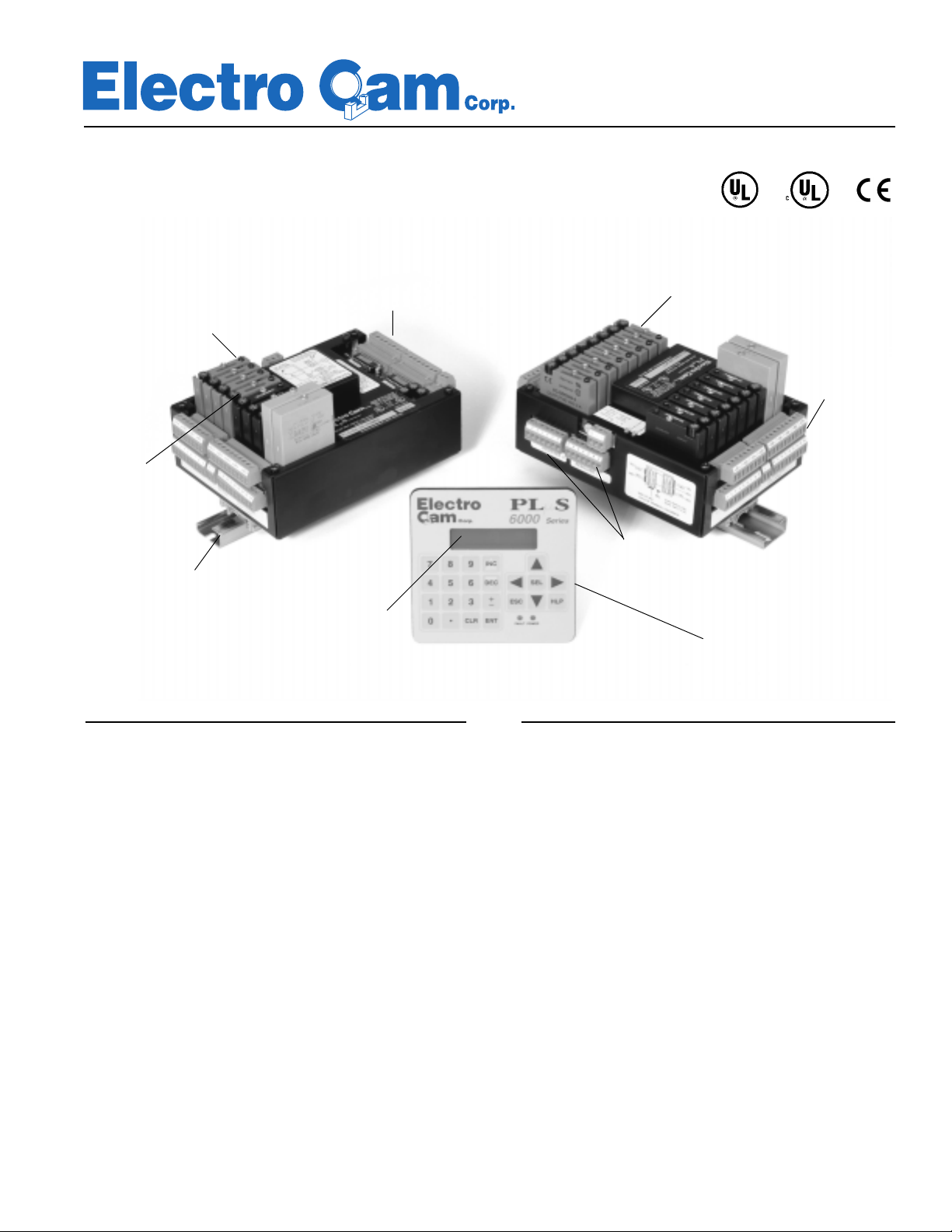
PS-6000 Series
Programmable Limit Switches
PL
µ
S
Controls Div.
Available with Modbus™ ASCII Communications
16 DC Logic Level
*Slimline Modules
have built-in
Fuses & LED's
*9 Plug-In
Output Modules for
Real World Control of
Electro-Mechanical
Devices
PS-6144-24-P16M09
DIN Rail
Mountable
* Modules sold separately.
Available in AC, DC, Analog &
Reed Relay
Outputs for Direct
Interfacing to PLC's
Controller
2-Line Backlit
Supertwist
LCD Display
Controllers
can be used
with or without
Keypad/Display
PS-6400-24-001
Keypad/Display
*17 Plug-In
Output Modules for
Real World Control of
Electro-Mechanical
Devices
Plug-In
Terminal Blocks
Simplify Wiring
Dual Resolver
Inputs
Compact 1/4 DIN Keypad/Display mounts remotely.
Multiple keypads may be used with one controller.
PS-6344-24-M17
Controller
Description
The PLµS PS-6144 Series Programmable Limit Switches
are microprocessor based units designed to control machine
functions on automated equipment. They can be used as
stand-alone controllers, or interfaced to PLC’s in larger automation systems.
Benefits
Improved Machine Control
Features such as automatic speed compensation, combined
with fast scan times, enable a PLµS Controller to quickly respond to changes in line speed and product movement, minimizing machine errors and reducing scrap and downtime.
The PLµS PS-6344 Programmable Dual Axis Limit Switch
is designed to control machine functions on two independent
axes. It can also be used as a stand-alone controller, or interfaced to PLC's in larger automation systems.
Easier Operator Control
By handling complex automation functions under rapidly
changing line conditions, PLµS Controllers allow an operator
to concentrate on product flow into and out of the line, instead
of constantly monitoring the line for malfunctions and manu-
Typical applications include:
■ Polybag Machines ■ Cartoners
■ Labelling Machines ■ Case Packers
■ Can Making Machines ■ Palletizers
■ Form-Fill-Seal Machines ■ De-Palletizers
■ Paper Converting Machines ■ Vision Systems
■ Pick & Place Machines ■ Filling Machines
■ Metal Processing/Stamping ■ Beverage Fillers
■ Adhesive Application Systems ■ High Speed Presses
■ Automatic Assembly Machines
ally adjusting setpoints. PLµS Controllers increase operator
interface capabilities and contribute to smooth, efficient production.
Faster Changeovers, Greater Flexibility
PLµS Controllers can store multiple programs of timing
setpoints for solenoids, cylinders, motors, glue guns, and other
mechanisms. This allows quick changes in product size or
configuration, reducing downtime and improving productivity.
13647 Metric Rd • Roscoe, IL 61073 USA • 815-389-2620 • FAX 815-389-3304 • 800-228-5487 (USA & Canada)

PLµS Controllers Enhance PLC Systems
PLµS Controllers are Fast!
As the system in
duction line every 300 to 500 µsec, approximately 100 times
faster than an average PLC with its more extensive programming. Although the PLC does interface directly with the production line, the functions it controls are lower speed, and deals
more with the logic functions necessary for machine control.
For high speed, critical functions such as label-to-product registration, the PLµS provides faster control and improved precision, reducing scrap and rejects.
Figure 1
shows, the PLµS monitors the pro-
PLµS Controllers have Built-In DC Inputs & Outputs!
Using transistor outputs, the PLµS can signal changes to the
PLC within 300 to 500 µsec (as fast as 40 µsec on special models); much faster than the serial communications speed of approximately 50 msec. When product sensors send a signal to
the DC input of the PLµS, the PLµS responds to that signal
quickly.
PLµS Controllers have Serial Communications!
For product changeovers, the PLC can send commands and
operating parameters to the PLµS controller to change setpoint
programs. This eliminates the need for an operator to manually
change programs through the PLµS keyboard.
PLµS Controllers Save PLC Memory!
The PLµS controller can store many programs containing various setpoints for the production line. The PLC need only select
the correct program, and the PLµS will do the rest.
Figure 1
PLµS Controllers Simplify PLC Programming!
By handling complex functions like speed compensation, timed
outputs, and sensor gating, the PLµS controller relieves a programmer of having to write complicated PLC control programming from scratch. The PLC software can simply exchange
process variables and control data with the PLµS controller,
which handles direct high speed machine control through its
own dedicated software.
PLµS Controllers Simplify Operator Interface Design!
Many production lines require an operator to select product
sizes or configurations through a keyboard. The 1/4 DIN keypad/display of the PS-6000 can be mounted near the production machinery, giving an operator easy access to critical control functions. The keypad transmits these changes back
through the PLµS controller to the PLC, eliminating the need
for a PLC system designer to supply custom operator interface
software and hardware for PLS functions.
Electro Cam Corp. has Systems Experience!
Our standard PLµS controllers feature extensive capabilities
for integration into larger control systems, PLC based or otherwise. We can supply IBM-PC compatible PLuSNet software to
facilitate communications between our controllers and a host
computer. In addition, we can supply controllers with custom
features such as shift-register capability, or the ability to function in non-rotary environments. For information on our systems capabilities, please call our toll free number.
800-228-5487
2

Standard PS-6000 Series Features
Analog Output
PS-6000 controllers can drive two analog output modules whose
output signals will be linearly proportional to RPM. The analog
signal level at zero RPM can be programmed, as well as the
RPM that corresponds to maximum signal. No measuring equipment is required for initial setup, and calibration is not needed.
Typical uses for the analog output are to control adhesive pressure as machine speeds change, or to match speeds of other
equipment to the machine being controlled by the PS-6000.
Multiple Programs
Up to 48 programs can be stored in the control’s memory, each
containing different setpoints. To change product size or configuration, simply switch program numbers and all of the output settings will change accordingly. Program numbers can be
selected by the keypad/display, mechanical switches, PLC DC
outputs, or serial communication messages.
Output Speed Compensation
Speed compensation allows outputs to compensate for lagging response times of the controlled devices by turning on
earlier as machine speeds increase. This eliminates the need
to manually adjust output settings whenever machine speeds
are changed, allowing high production speeds.
Internal High Speed Logic
Outputs can be divided into Groups, and each Group can be
associated with an input device to perform discrete logic. There
are six different modes of operation, or logic functions, that
can be selected for each Group. For example, some modes
activate the Group only when the input has signaled that product is present. Adhesive control is a typical application where
outputs are disabled until product is sensed. Output grouping
is a powerful tool in many applications because each Group
can be in any of the six modes and operate independently of
the other Groups.
Timed Outputs
Timed outputs are programmed like standard outputs to turn
“ON” and “OFF” at specific points of resolver rotation. However, once a timed output turns ON, it will remain ON for a
specified time period. Timed outputs are used to drive devices
such as heat seal bars, spot welders, etc., that require a fixed
time to perform a task, regardless of machine speed.
Selectable Scale Factor
The Scale Factor, or number of increments per revolution, can
be programmed by the user. Standard controls have a maximum of 1024 increments per revolution, while controls available with an “-H” option have a maximum of 4096 increments
per revolution. Scale Factor can be defined to correlate to Real
World increments. For example, a controller could be programmed so that one increment of rotation corresponds to 0.1"
of travel.
Serial Communication
Using Electro Cam Corp.’s PLuSNet software for IBM-PC compatible computers, the controller’s entire program can be saved
to a disk file or loaded from a disk file to the control. The program can be printed or edited using the computer. Using MMI
software, it is also possible to send individual communication
commands to the control, while running, to change settings in
the program.
Motion Detection
Two speed ranges can be programmed into the controller, and
specified outputs can then be enabled or disabled, based on
the machine speed being within the designated range. This feature can turn off outputs if the machine stops; disable outputs
until the machine reaches a minimum speed; or disable outputs if the machine exceeds a specified speed. In adhesive
applications, speed range logic is often used to turn off the flow
of adhesive if the conveyor carrying products stops.
Certifications are standard.
PS-6000 Series Options
Gray Code Position Output, “-G” & “-G10”
The “-G” option provides eight bits of position information to a
PLC or other electronic control device, eliminating the need for
expensive PLC accessory cards. The "-G10" option provides
ten bits of position information. This allows the PLC to control
non-critical machine functions, while the PLµS directly handles
high-speed machine control.
High Resolution, “-H”
Controls with this option can divide the resolver revolution into
as many as 4096 increments, while standard controls have a
maximum of 1024 increments. The control program allows resolver resolution to be set for any value in the range of 2-4096.
Large Program Memory, “-F”
Controls with the “-F” option can store up to 256 programs consisting of not more than 4589 output pulses total; standard controls can store up to 48 programs. This additional program storage capability is useful for applications requiring multiple complex programs, or those requiring the storage of more than 48
programs.
Leading/Trailing Edge Speed Comp, “-L”
Controls with this option allow the "ON" and "OFF" edges of
output pulses to be speed compensated by different amounts.
If a device has “ON” and “OFF” response times that are different, it may be necessary to compensate the “ON” edge by a
different amount than the “OFF” edge. This will ensure that the
device stays properly synchronized to the machine over a wide
range of speeds. High-speed adhesive application is an example that can benefit from this feature.
NEMA 4X Keyboard Boot, “-W”
Controls with the “-W” option are shipped with a clear silicon
rubber boot fitted over and around the keyboard area. The boot
provides a good seal between the back of the keyboard and the
control panel. The boot is transparent and pliable, allowing the
keyboard to be viewed and operated. In addition to preventing
contamination from harsh chemicals, the boot protects the keyboard from washdown damage.
Modbus™ ASCII Communication, “-MB”
See page 4.
Multiple Controllers Used with One Resolver, “-MSV”
See page 5.
3
PS-6000 Series with -MB Option
— with Modbus ™ ASCII Communications
Description
Standard Modbus™ ASCII protocol allows a host computer,
Programmable Logic Controller (PLC), intelligent touch panel,
or other compatible logic circuitry to easily monitor or modify
data within the PS-6000-MB while the machine is in motion.
The control data in the PS-6000-MB is organized as registers
and coils, compatible with PLC programming techniques. Registers are used to store control parameters at specific addresses.
Coils represent channel outputs and logic inputs. Through serial communications, coils allow outputs to be forced ON or OFF,
and allow inputs to be monitored.
The data can be changed by writing to registers, and monitored
by reading from registers. All controller data, including position,
pulses, RPM, speed compensation, and timed output values,
are available through registers.
NOTE: All other features of the -MB version of 6000 series
controllers are the same as those for standard PS-6000
series controllers.
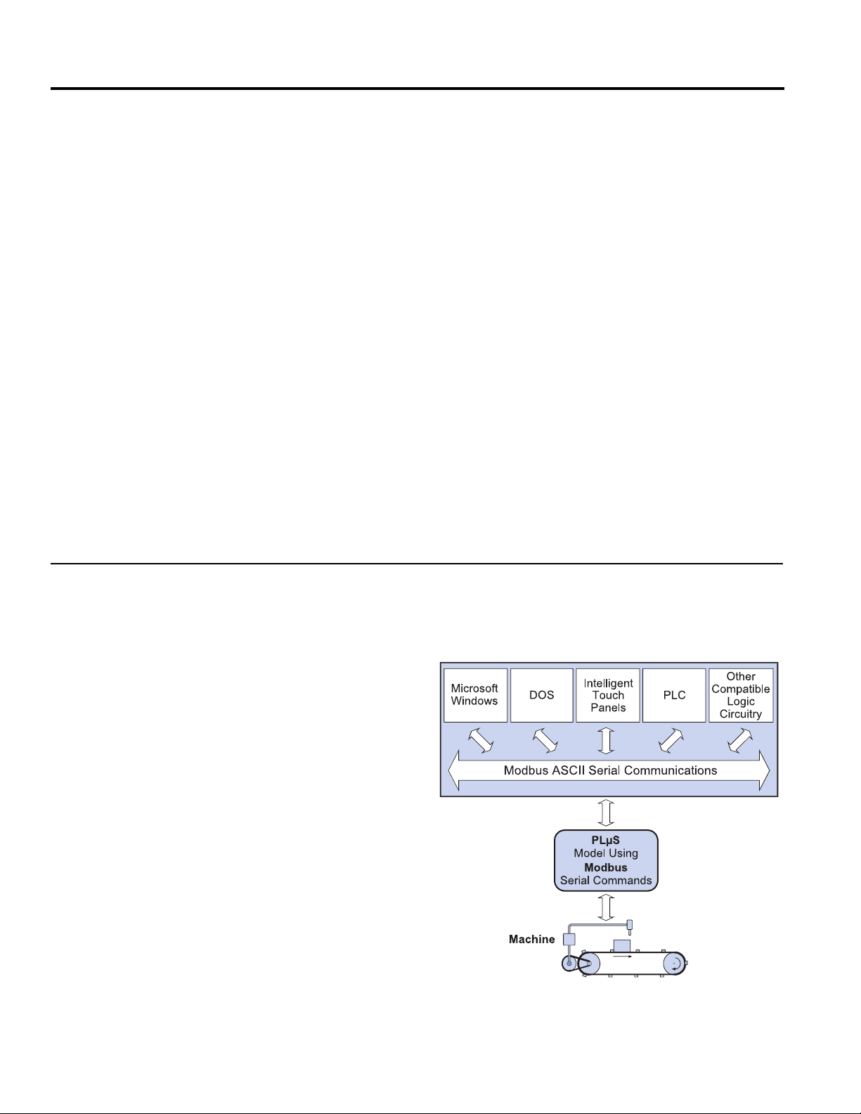
PS-6000-MB System Configuration
Benefits
Improved Machine Control
The controller quickly responds to changes in line speed and
product movement by combining automatic speed compensation with fast scan times. Modbus serial communications makes
it easy to integrate the PLµS controller's high-speed control
characteristics into larger control systems.
Messaging Capability
The PLµS keypad/display can display stored messages or messages received from a host computer. Each message, containing up to 32 characters, is stored in non-volatile EEPROM
memory.
Mapping
Mapping allows the programmer to arrange data into blocks of
registers for optimal communication efficiency, giving direct
access to specific indexed data items. For example, setpoint
values may be mapped into a series of direct access registers
in order to display more than one value at once on the host
computer.
The Modbus™ ASCII protocol allows the PS-6000-MB Series
controller to communicate with various control hardware and
software, including:
■ PC's using Microsoft
FactoryLink®, Intellution™, Lookout™, and Wonderware
■ PC's using DOS software such as Interact™
■ Intelligent Touch Panels
■ PLC's
As the diagram in
municates to the PLµS using Modbus™ ASCII serial communications. The PLµS controller handles high-speed machine
functions through direct wiring of inputs and outputs to the machine.
The Modbus serial commands in the PS-6000-MB Series controller allow you to monitor the program, adjust the current program, or change the program through a host computer system.
This allows the flexibility to change product size or configuration quickly and automatically, reducing downtime and improving productivity.
Figure 2
®
Windows™ software such as
illustrates, the host computer com-
®
Figure 2
4

PS-6000 Series with -MSV Option
Description
The -MSV (Master-Slave) option allows up to four controllers
to be daisy-chained to one resolver. Controllers with the -MSV
option are equipped with a jumper that the user can plug/unplug to configure the unit to be either a master or a slave. The
controller comes from the factory jumpered as a master, but
can be set to slave status by removing the jumper.
shows jumper location:
Figure 3
Figure 3
The wiring of the resolver is daisy-chained to all of the controllers as shown below in
supplies the reference signal to the resolver and slave units.
The resolver supplies the position information to all units. Only
a single unit can be the master. Daisy-chain the power from
controller to controller in the same way as the resolver signals.
Connect one of the controllers directly to the power supply.
Power for the other devices in the system should come directly
from the power supply. DO NOT power other devices from the
wires powering the controllers. This will help reduce the risk of
problems associated with EMI and ground loops. Use the standard resolver cable from master to resolver. Use a PS-530005-XXX resolver cable from the master to slave controllers, and
from slave to slave.
NOTE: PS-6344 Series Controllers include Master-Slave
feature as standard.
All other features of the -MSV version of 6000 series controllers are the same as those for standard PS-6000 series
controllers.
Figures 4 & 5
. The master controller
Figure 4
Figure 5
5

PS-6X44 Specifications
Controller PS-6144-24-P16M09 (Sourcing
Part Numbers PS-6144-24-N16M09 (Sinking
PS-6344-24-P16M09 (Sourcing
PS-6344-24-N16M09 (Sinking
Electrical
Input Voltage
Input Current
Permanent Memory
20-30 VDC
System: 850 mA max. @ 20 VDC. Includes controller,
2 keypads, resolver, 16 transistor outputs, 7 power modules, 2 analog modules, and 16 inputs, all ON. Current
will be less at higher voltage.
Controller only: 150 mA max. @ 20 VDC
Controller, Resolver, 1 Keypad: 275 mA max @ 20 VDC
EEPROM (no battery required) EEPROM (no battery required)
Environment
Operating Temp.
Storage Temp.
Humidity
NEMA Rating
0° to 55°C (32° to 131°F)
-40° to 70°C (-40° to 160°F)
95% maximum relative non-condensing
For use on type 1, 4, 4X or 12 enclosure
Physical
Overall Dimensions
Weight
See Dimensions (Figures 4 & 5) on page 8.
Controller: 3.5 lbs. (1.6 kg). Keypad/Display: 0.5 lbs.
(0.2 kg)
†
Transistor Outputs)
†
Transistor Outputs) PS-6144-24-M17
†
Transistor Outputs)
†
Transistor Outputs) PS-6344-24-M17
20-30 VDC
System: 850 mA max. @ 20 VDC. Includes controller,
2 keypads, resolver, 15 power modules, 2 analog modules and 16 inputs, all ON. Current will be less at higher
voltage.
Controller only: 150 mA max. @20 VDC
Controller, Resolver, 1 Keypad: 275 mA max @ 20 VDC
0° to 55°C (32° to 131°F)
-40° to 70°C (-40° to 160°F)
95% maximum relative non-condensing
For use on type 1, 4, 4X or 12 enclosure
See Dimensions (Figures 4 & 5) on page 8.
Controller: 3.5 lbs. (1.6 kg). Keypad/Display: 0.5 lbs.
(0.2 kg)
Mounting
Controller
Keypad/Display
Inputs
DC Inputs
Input On State Voltage
Input Current
Input Response Times
Outputs
PS-6144 Series
Real World Outputs
Analog Outputs
DC (transistor) Outputs
Brackets accept EN-50035 ("G" profile) or EN-50022
("Top Hat" profile) DIN rail.
Mounts up to 1000' from controller. Up to 2 keypads
may be connected to one controller.
16 DC inputs; can be configured as sinking† or sourcing
in groups of 8. Optically isolated in groups of 8.
10-30 VDC
11 mA @ 24 VDC
1 - 2 scans
Up to 9 SLIMLINE modules may be plugged into controller. Modules may be any mix of AC, DC, reed relay, & up
to 2 analog. All modules optically isolated.
Up to two 4-20 mA or 0-10 VDC SLIMLINE analog modules may be plugged into controller. Output proportional
to RPM. 12 bit resolution. Update frequency 10 times/
sec (100 msec). Linearity is ±0.3% @ 77°F (25° C). Offset & full scale RPM are programmable.
16 sinking† or sourcing†, optically isolated. 30 VDC,
50 mA max. each. Note: Sinking† or sourcing† must be
specified on order.
Brackets accept EN-50035 ("G" profile) or EN-50022
("Top Hat" profile) DIN rail.
Mounts up to 1000' from controller. Up to 2 keypads
may be connected to one controller.
†
16 DC inputs; can be configured as sinking† or sourcing
in groups of 8. Optically isolated in groups of 8.
10-30 VDC
11 mA @ 24 VDC
1 - 2 scans
Up to 17 SLIMLINE modules may be plugged into controller. Modules may be any mix of AC, DC, reed relay, &
up to 2 analog. All modules optically isolated.
Up to two 4-20 mA or 0-10 VDC SLIMLINE analog modules may be plugged into controller. Output proportional
to RPM. 12 bit resolution. Update frequency 10 times/
sec (100 msec). Linearity is ±0.3% @ 77°F (25° C). Offset & full scale RPM are programmable.
†
Outputs
PS-6344 Series
†
See page 12 for sinking/sourcing definitions.
Outputs are assignable to each resolver.
Outputs are assignable to each resolver.
Specifications continued...
6

PS-6X44 Specifications (continued)
Controller PS-6144-24-P16M09 (Sourcing
Part Numbers PS-6144-24-N16M09 (Sinking
PS-6344-24-P16M09 (Sourcing
PS-6344-24-N16M09 (Sinking
Operation
Scan Time
Position Resolution
Speed Compensation
Output Timeout
Number of Timed
Outputs
Multiple Programs
Total Pulse Memory
Pulses per Program
Pulses per Output
Maximum Speed
300 to 500 µsec typical (exact time determined by programming). For higher speeds, interrupt driven versions
are available — consult factory.
10 bits (1024 increments). 12 bits (4096 increments)
available with "-H" option.
Programmed in 0.1 msec steps. 16 individually compensated outputs maximum. Calculations every 10
msec. Special algorithm prevents false firing under rapid
acceleration and deceleration. Separate leading/trailing edge compensation available with "-L" option.
1.0 msec time base (accuracy +1, -0 msec)
Four maximum
48 programs standard (256 available with "-F" option).
1258 pulses standard (4589 available with "-F" option).
512 maximum standard (512 available with "-F" option).
512 maximum standard (512 available with "-F" option).
3000 RPM
†
Transistor Outputs)
†
Transistor Outputs) PS-6144-24-M17
†
Transistor Outputs)
†
Transistor Outputs) PS-6344-24-M17
300 to 500 µsec typical (exact time determined by programming). For higher speeds, interrupt driven versions
are available — consult factory.
10 bits (1024 increments). 12 bits (4096 increments)
available with "-H" option.
Programmed in 0.1 msec steps. 16 individually compensated outputs maximum. Calculations every 10
msec. Special algorithm prevents false firing under rapid
acceleration and deceleration. Separate leading/trailing edge compensation available with "-L" option.
1.0 msec time base (accuracy +1, -0 msec)
Four maximum
48 programs standard (256 available with "-F" option).
1258 pulses standard (4589 available with "-F" option).
512 maximum standard (512 available with "-F" option).
512 maximum standard (512 available with "-F" option).
3000 RPM
RS-232/485 Serial
Communication
Port Types
Baud Rates
Slimline Output
Modules
0-60 VDC, 0-3 amps
0-200 VDC, 0-1 amp
24-280 VAC rms,
50/60 Hz. 0.02-3 amps
Reed Relay
Analog, 0-10 VDC
Analog, 4-20 mA DC
Keypad/Display
(Up to 2 keypad/displays can be
used with one controller)
Keypad/Display w/Gasket
Cable, Keypad-to-Controller
Resolvers & Cables
1 RS-232 or 1 RS-422/485 — RS-485 can be configured as a "Multi-Drop" network.
4800, 9600, 19.2K, 38.4K
Part Numbers
EC-ODC060-3
EC-ODC200-1
EC-OAC240-3
EC-ORR000-0
EC-SANL-010V
EC-SANL-420M
PS-6400-24-001
PS-6300-01-XXX (XXX = length in feet)
Electro Cam Corp. offers a wide variety of resolver
models, shaft sizes, & mounting configurations, including a stainless steel resolver. The cable required
depends on the resolver. Contact Electro Cam for
details.
Note: Controllers may be used with or without keypad/display.
†
See page 12 for sinking/sourcing definitions.
7

PS-6X44 Controllers & PS-6400 Keypad/Display Dimensions
Figure 3
PS-6400-24-001 Keypad/Display
†
See page 12 for sinking/sourcing definitions.
Figure 4
PS-6144-24-M17
PS-6144-24-P16M09 (Sourcing†)
PS-6144-24-N16M09 (Sinking†)
Figure 5
PS-6344-24-M17
PS-6344-24-P16M09 (Sourcing†)
PS-6344-24-N16M09 (Sinking†)
8

Resolvers
The 7-pin resolver connector is supplied as part of the PLµS Programmable Limit Switch Controllers effective with date
code 9723. Prior to that date code, connectors were supplied on the resolver cables. Spare 7-pin resolver connectors
that plug into controllers may be purchased under part number PS-5300-01-TER. Some resolver configurations are
shown below. See Price List (Literature #202) for complete listing.
PS-5275-11-ADS
Foot Mount
• 3/4" Shaft
• Top side, Right side, Left side or Rear connection
PS-5238-11-SDR
Servo Mount
• 3/8" Shaft
• Top side, Right side, Left side or Rear connection
PS-5238-11-ADR
Flange Mount
• 3/8" or 5/8" Shaft
• Top side, Right side, Left side or Rear connection
PS-5262-11-CTG
Stainless Steel
• 5/8" Shaft
• Left side or Right side connection
PS-5275-051-ADL*
Foot Mount Geared
• 3/4" Shaft
• 5:1 Gear Ratio
• Top side, Right side or Left side connection
*Also available in 10:1 and 36:1 Ratio
PS-5212-11-SVW
Unhoused Servo Mount
• .120" Shaft
• Standard Size 11
9

Resolver Dimensions
Foot Mount
With Rear Connector (shown):
PS-5275-11-ADR
With Side Connector:
PS-5275-11-ADS
Cable:
PS-5300-01-XXX where "XXX" is length in feet.
Flange Mount
With Rear Connector (shown):
PS-5238-11-ADR
With Side Connector:
PS-5238-11-ADS
Cable:
PS-5300-01-XXX where "XXX" is length in feet.
Stainless Steel
With Right Connector (shown):
PS-5262-11-CTG
With Left Connector:
PS-5262-11-CTL
Cable:
PS-5300-02-XXX where "XXX" is length in feet.
Unhoused Servo Mount
Size 11, .120" Shaft:
PS-5212-11-SVW
Contact the Factory for detailed specifications on other available resolvers.
10

Controller Part Number Breakdown
P S - X X X X - X X - X X X(XXX) - X
PLuS Part Number
MODEL/DISPLAY SELECTION
6 - 1/4 DIN LCD Display
TRANSDUCER SELECTION
1 - Resolver Input
3 - 2 Resolver Input
INPUT/OUTPUT CONFIGURATION
4 - DC Transistor Outputs and/or SLIMLINE
Modules on Keyboard/Controller back
with input capability
FUNCTIONS
4 - Output Enable Modes & Standard Features
TYPE & NUMBER OF OUTPUTS
M17 - 17 SLIMLINE AC and/or DC Module Outputs, 2 of which may be analog
N16M09 -16 DC Sinking† Transistor Outputs & 9 SLIMLINE AC and/or DC Module Outputs, 2 of which may be analog
P16M09 -16 DC Sourcing† Transistor Outputs & 9 SLIMLINE AC and/or DC Module Outputs, 2 of which may be analog
INPUT VOLTAGE
24 - (20 - 30 VDC Input)
OPTIONS
F - Additional setpoint/program
storage
G - Gray Code Output (8 bit)
G10
- Gray Code Output (10 bit)
H - High Resolution (12 bit-4096)
L - Leading & Trailing Edge
Speed Compensation
W - Washdown boot
MB - Modbus™ communication
protocol available for
PS-6X44 Models
MSV
- Multiple Controllers used
with one resolver
Resolver Part Number Breakdown
P S - 5 2 X X - X X X - X X X
PLuS Part Number
Resolver
SHAFT SIZE
12 - 1/8 DIA.
15 - 15 mm DIA.
20 - 20 mm DIA.
38 - 3/8” DIA., 2.06” Bolt Flange
62 - 5/8” DIA., 2.25” Bolt Flange
75 - 3/4” DIA.
RATIO
11 - Standard 1:1 (Note: 3rd digit not used on Standard 1:1)
051 - Geared 5:1 - Ext. shaft to internal resolver shaft
101 - Geared 10:1 - Ext. shaft to internal resolver shaft
361 - Geared 36:1 - Ext. shaft to internal resolver shaft
†
See page 12 for sinking/sourcing definitions.
HOUSING
A - Can housing w/flange or foot endbells
C - Stainless steel square housing
E - 74 mm bolt spacing, flange mount
S - Servo mount ( .12 = size 11; .38 - size 25 )
TYPE OF CABLE CONNECTION
D - Military bayonet style connector
T - Terminal strip with NO conduit entrance
V - No connector, just stripped & tinned wires
S - Sealed connector — screw type
Note: Part # PS-5903-01-001 conduit entrance for
terminal strip models sold separately
LOCATION OF CABLE CONNECTION
W- With stripped & tinned leads
G - Right (120° from top on “A” housings)
R - Rear (not available on Geared Resolver)
L - Left (120° from top on “A” housings)
S - Side (Top)
11

Typical System(s)
Component(s) Qty. Part Number
PS-6X44 Controller(s) (1) PS-6144-24-P16M09-L
PS-6400 Keypad/Display(s) (1) PS-6400-24-001
Keypad-to-Controller Cable(s) (1) PS-6300 -01-005
Resolver(s) (1) PS-5275-11-ADR
Resolver Cable(s) (1) PS-5300-01-010
SLIMLINE Output Modules (7) EC-ODC060-3
SLIMLINE Analog Modules (2) EC-SANL-010V
†
SINKING or SOURCING ( as pertaining to Electro Cam Corp. products )
Sinking
DC common or ground to the connected device.
Sourcing
a +DC voltage to the connected device.
This information is important when interfacing an Electro Cam Corp. product with another electronic device. The terms
SINKING / SOURCING
product input to an Allen-Bradley 1746-IN16 “sinking” input card* or similar A-B de vice, y ou hav e to supply a +DC v oltage to
this card, NOT a DC common or ground. In these cases,
common or ground.
* Other manufacturers include, but not limited to: Koyo (formerly GE Series 1, Texas Instruments, or Siemens SIMATIC PLS’s) that use
descriptions similar to Allen-Bradley.
means that when the logic is true and the output (or input device) is ON, the output (or input device) is providing a
means that when the logic is true and the output (or input device) is ON, the output (or input device) is pro viding
are not used in the same context by all manufacturers. If you are using an Electro Cam Corp.
Sinking
is what the card does with the input voltage; sinks it to
Electro Cam Corp. is highly experienced in supplying
automation solutions to a variety of industrial machinery.
For assistance with your application, please call us.
800-228-5487
221 04/98
13647 Metric Rd • Roscoe, IL 61073 USA • Web Site: http://www.electrocam.com • email: ecam@electrocam.com
 Loading...