


 Loading...
PLμS® PS-5000 Series
Programmable Limit Switch
Programming &
Installation Manual
October 2001
13647 Metric Rd • Roscoe, IL 61073 USA • 815/389-2620 • FAX 815/389-3304 • 800-228-5487 (U.S.A. and Canada)

Copyright © 2001
All Rights Reserved
Neither this document nor any part may be reproduced or transmitted in any form or by any means without permission in writing from the publisher.
® , PLμS® , SLIMLINE® , and PLμSNET® are all registered trademarks of 

Table of Contents
Section—Introduction
Basic Cam Switch Operation . . . . . . . . . . . . . . . . . . . . . 1-1
Standard Features . . . . . . . . . . . . . . . . . . . . . . . . . . . |
1-1 |
Optional Features . . . . . . . . . . . . . . . . . . . . . . . . . . . |
1-2 |
Model Summary . . . . . . . . . . . . . . . . . . . . . . . . . . . |
1-3 |
Section 2—Dimensions & Component Locations
Controllers with External I/O Module Rack
5001, 5101, 5004, 5104, 5034, 5134 . . . . . . . . . . . . 2-1
Controllers with I/O Modules on Controller Back
5021, 5121, 5024, 5124 . . . . . . . . . . . . . . . . . . . . . . 2-2
Controllers with Built-In Transistor I/O Chips |
|
|
5011, 5111 . . . . . . . . . . . . . . . . . . . . . . . . . . . . . . |
. . 2-3 |
|
Section 3—Wiring |
|
|
Logic Terminal Strip Wiring . . . . . . . . . . . . . . . . . . . . |
. . 3-1 |
|
External I/O Racks (5001, 5101, 5004, 5104) |
|
|
16 |
Module I/O Rack—Standard . . . . . . . . . . . . . . |
. . 3-2 |
16 |
Module I/O Rack—Analog . . . . . . . . . . . . . . . . |
. . 3-2 |
16 |
Module I/O Rack—M16 Slimline . . . . . . . . . . . |
. . 3-2 |
24 |
& 48 I/O Rack . . . . . . . . . . . . . . . . . . . . . . . . . |
. . 3-3 |
I/O Modules on Controller (5021, 5121, 5024, 5124) |
. . 3-4 |
|
Module Wiring, Outputs . . . . . . . . . . . . . . . . . . . . . . . |
. . 3-4 |
|
Sinking/Sourcing Defined . . . . . . . . . . . . . . . . . . . . . |
. . 3-5 |
|
Module Wiring, Inputs . . . . . . . . . . . . . . . . . . . . . . . . |
. . 3-5 |
|
Input Wiring, 3-Wire Sensors . . . . . . . . . . . . . . . . . . . . . 3-5
Built-In Transistor I/O Chips (5011, 5111)
Description . . . . . . . . . . . . . . . . . . . . . . . . . . . . . . . . 3-6 Output Wiring, Sourcing . . . . . . . . . . . . . . . . . . . . . . 3-7 Output Wiring, Sinking . . . . . . . . . . . . . . . . . . . . . . . 3-8 Output Wiring to PLC . . . . . . . . . . . . . . . . . . . . . . . . 3-9 PS-5X34 Controller & 32 DC Output Rack . . . . . . . 3-10 PS-5X34 Output Rack Layout . . . . . . . . . . . . . . . . 3-11 PS-5X34 Wiring to PLC's . . . . . . . . . . . . . . . . . . . . 3-12 PS-5X34 Output Rack Transistor Array Chips . . . . 3-13
Resolver Wiring . . . . . . . . . . . . . . . . . . . . . . . . . . . . . . 3-14
Cable for Stainless Steel Resolver . . . . . . . . . . . . . . . |
3-15 |
|
Encoder Cable Installation . . . . . . . . . . . . . . . . . . . . . . |
3-16 |
|
Section 4—Programming, Standard Features |
|
|
Access Levels |
. . . . . . . . . . . . . . . . . . . . . . . . . . . . . . . |
. 4-1 |
Keyboard Description . . . . . . . . . . . . . . . . . . . . . . . . . . |
4-2 |
|
Output Setpoint Programming . . . . . . . . . . . . . . . . . . . . |
4-3 |
|
Master Level Programming |
|
|
FCN 0 |
Programming Enable . . . . . . . . . . . . . . . |
4-4 |
dr |
Direction of Rotation . . . . . . . . . . . . . . . . |
4-4 |
SF |
Scale Factor . . . . . . . . . . . . . . . . . . . . . . |
4-4 |
P1 & P2 |
Keyboard Enable . . . . . . . . . . . . . . . . . . |
4-4 |
tb |
Time Base for Output Timing . . . . . . . . . |
4-5 |
Enhanced Position/RPM Display Logic . . . . . . . . . . |
4-5 |
|
dd |
Display Default . . . . . . . . . . . . . . . . . . . . |
4-5 |
tr |
Toggle RPM . . . . . . . . . . . . . . . . . . . . . . |
4-5 |
rU |
rPM Display Update Frequency . . . . . . . |
4-6 |
ct, cS, cA Communications Parameters . . . . . . . . . . |
4-6 |
|
FCN 6 |
Output Channel Access . . . . . . . . . . . . . |
4-7 |
FCN 7 |
Motion ANDing . . . . . . . . . . . . . . . . . . . . |
4-8 |
FCN 8 |
Subdividing Outputs . . . . . . . . . . . . . . . . |
4-9 |
FCN 9 |
Enable Inputs and Modes . . . . . . . . . . . |
4-9 |
Setup Level Programming
FCN 1 Motion Setpoints . . . . . . . . . . . . . . . . . . 4-10 FCN 2 Offset . . . . . . . . . . . . . . . . . . . . . . . . . . 4-10 FCN 3 Program Number . . . . . . . . . . . . . . . . . 4-10 FCN 4 Speed Compensation, Standard . . . . . 4-12 Speed Compensation, Negative . . . . . 4-12 FCN 5 Timed Outputs . . . . . . . . . . . . . . . . . . . 4-13
Section 5—Programming, Optional Features
Leading Trailing Speed Comp (“-L”)
FCN 0 Speed Comp Type . . . . . . . . . . . . . . . . . 5-1 FCN 4 Leading/Trailing Speed Comp . . . . . . . . 5-1
Analog Output (“-A”)
FCN 1 Analog Offset & High RPM . . . . . . . . . . . 5-2
Outputs Based on Direction of Rotation (“-D”)
Direction ANDing . . . . . . . . . . . . . . . . . . . . . . . . . . . 5-2 Direction Hysteresis . . . . . . . . . . . . . . . . . . . . . . . . . 5-2
Gray Code Output (“-G”)
Gray Code Conversion Ladder . . . . . . . . . . . . . . . . . 5-3
FCN 4 Gray Code Speed Comp . . . . . . . . . . . . 5-3
Extra Program Storage (“-F”) |
|
|
Pulses/Programs Available . . . . . . . . . . . . . . . . . . . |
5-4 |
|
Program Number Displays . . . . . . . . . . . . . . . . . . . . |
5-4 |
|
FCN 3 |
Program Number Changes . . . . . . . . . . |
5-5 |
Viewing/Editing Program . . . . . . . . . . . . . . . . . . . . . |
5-6 |
|
Phase Mark Registration (“-P”)
Examples and Adjustment Methods . . . . . . . . . . . . . 5-7
Input Information . . . . . . . . . . . . . . . . . . . . . . . . . . . 5-8
CHN 80 Auto-Center Registration . . . . . . . . . . . . 5-9
CHN 81 Adjust Registration Center . . . . . . . . . . . 5-9
Reversal of Centering Logic . . . . . . . . . . . . . . . . . . 5-10
“OFF” Logic Examples . . . . . . . . . . . . . . . . . . . . . . 5-10
Appendix
Output Grouping & Modes
Introduction . . . . . . . . . . . . . . . . . . . . . . . . . . . . . . . . A-1
Configuration Examples . . . . . . . . . . . . . . . . . . . . . . A-2
Mode 0 . . . . . . . . . . . . . . . . . . . . . . . . . . . . . . . . . . . A-3
Mode 1 . . . . . . . . . . . . . . . . . . . . . . . . . . . . . . . . . . . A-4
Mode 2 . . . . . . . . . . . . . . . . . . . . . . . . . . . . . . . . . . . A-6
Mode 3 . . . . . . . . . . . . . . . . . . . . . . . . . . . . . . . . . . . A-8
Mode 4 . . . . . . . . . . . . . . . . . . . . . . . . . . . . . . . . . . A-10
Error Messages . . . . . . . . . . . . . . . . . . . . . . . . . . . . . . A-12
Communication Port Wiring . . . . . . . . . . . . . . . . . . . . . A-14
Encoder Position vs. Degrees . . . . . . . . . . . . . . . . . . . A-15
60 Pulse Disc—Position vs. Degrees . . . . . . . . . . . . . |
A-15 |
|
Alternate Functions |
. . . . . . . . . . . . . . . . . . . . . . . . . . |
A-16 |
Alt Fcn 1 |
Transducer Position |
|
Alt Fcn 2 |
Logic Input Status |
|
Alt Fcn 3 |
Offset Value |
|
Alt Fcn 4 |
60 Pulse Disc |
|
Alt Fcn 1002 |
Keyboard Test |
|
Alt Fcn 1003 |
LED Display Test |
|
Alt Fcn 1004 |
Watchdog Timer Test |
|
Alt Fcn 1005 |
Control Model Info |
|
Alt Fcn 1006 |
Options & Rev. # |
|
Alt Fcn 7000 |
Restore Defaults |
|
Alt Fcn 7001 |
Clear Setpoints |
|
Alt Fcn 7999 |
EEPROM Test |
|
Remote Display Installation . . . . . . . . . . . . . . . . . . . . . |
A-17 |
|
Specifications |
. . . . . . . . . . . . . . . . . . . . . . . . . . |
A-18 |
Index

WARRANTY
1.Electro Cam Corp. warrants that for a period of twelve (12) months from the date of shipment to the original purchaser, its new product to be free from defects in material and workmanship and that the product conforms to applicable drawings and specifications approved by the Manufacturer. This warranty period will be extended on Distributor or OEM orders to a maximum of eighteen months to take into consideration Distributor or OEM shelf time.
2.The remedy obligations of Electro Cam Corp. under this warranty are exclusive and are limited to the repair, or at its option, the replacement or refund of the original purchase price of any new apparatus which proves defective or not in conformity with the drawings and specifications. Shipment of the claimed defective product to Electro Cam Corp. shall be at the cost of the consumer. Shipment of the repaired or replacement product to the consumer shall be at the cost of Electro Cam Corp. All claims must be made in writing to Electro Cam Corp., 13647 Metric Road, Roscoe,
IL 61073 USA.
3.In no event, and under no circumstances, shall Electro Cam Corp. be liable for:
a.Any product damaged or lost in shipment. Inspection for damage should be made before acceptance or signing any delivery documents releasing responsibility of the delivering carrier.
b.Product failure or damages due to misuse abuse, improper installation or abnormal conditions of temperature, dirt or other contaminants as determined at the sole discretion of Electro
Cam Corp.
c.Product failures due to operation, intentional or otherwise, above rated capacities as determined at the sole discretion of Electro Cam Corp.
d.Non-authorized expenses for removal, inspection, transportation, repair or rework. Nor shall the manufacturer ever be liable for consequential and incidental damages, or in any amount greater than the purchase price of the equipment.
4.There are no warranties which extend beyond the description on the face hereof. This warranty is in LIEU OF ALL OTHER WARRANTIES, EXPRESSED OR IMPLIED INCLUDING (BUT NOT LIMITED TO) ANY IMPLIED WARRANTIES OF MERCHANTABILITY OR FITNESS FOR A PARTICULAR PURPOSE, ALL OF WHICH ARE EXPRESSLY DISCLAIMED. Any legal proceeding arising out of the sale or use of this apparatus must be commenced within (18) months of the date of shipment from the manufacturer.

Introduction
Basic Cam Switch Operation
A PLμS control’s main purpose is to operate outputs in a manner that simulates cam switches. The drawing to the right illustrates the operation of a cam switch. Its function is to switch the load on and off at the same rotary positions of the cam shaft during each revolution of that cam shaft. The rotating cam shaft is driven by a machine at a 1:1 ratio, so that the on / off positions of the cam switch always match specific positions in the machine cycle. However, cam limit switches have the following disadvantages: unreliable (wear), hard to adjust (machine must be stopped during adjustment), and they cannot run at high speeds because of contact bounce and excessive mechanical wear.
PLμS controls overcome these basic cam switch problems. They have no moving wear parts, they are easy to adjust from the keyboard with the machine running or stopped, and they can operate at speeds up to 3000 RPM. They also add many capabilities far beyond simple cam switch logic.
Basic Cam Switch Operation
The limit switch will turn on and off at the same cam degree positions every cam revolution (every machine cycle)
Standard Product Features
Keyboard/Controller
The keyboard controller is the main component of the PLμS system. The front keypad and displays provide a complete user interface from which every aspect of the control’s operation can be monitored and programmed. When properly mounted with the gasket provided, the keyboard meets NEMA 4 standards. A clear silicon rubber boot assembly is available to provide NEMA 4X protection for installations where harsh washdown chemicals are used.
Ease of Setup
All output position setpoint values are simply entered through the numeric keypad. These setpoints can be adjusted while the machine is running or stopped by using the increment, decrement, or numeric keys. The keyboard is also used to synchronize the control’s position to the machine, eliminating the need to mechanically adjust the resolver’s shaft position.
Multiple Programs
Depending on the model ordered, up to 64 different programs, or “job recipes” can be stored in the control’s memory. This minimizes down time for job change over because simply changing program numbers makes all of the output setting changes required. Program numbers can be changed by mechanical switches; PLC’s (using the hardware program select inputs); the keypad; or serial communication messages.
Output Speed Compensation
Speed compensation allows outputs to compensate for the response time of the controlled devices by turning on earlier as machine speeds increase. This eliminates the need to adjust output settings whenever machine speeds are changed. Using speed compensation often allows higher production speeds and eliminates the need for output adjustments.
Motion ANDing
A speed range can be programmed into the controller, and outputs can then be ANDed with the speed range so that they will be disabled unless the machine speed is within the range. This can be used to turn off outputs if the machine stops; disable outputs until the machine reaches a minimum speed; or disable outputs if the machine goes above a specified maximum speed. A common use for this feature is disabling outputs to glue valves so the flow of glue turns off if the machine stops.
Timed Outputs
Outputs can be programmed to turn on at the programmed “on” position and turn off when the specified time elapses, rather than staying on until an “off” position is reached. The result is a constant output duration, regardless of machine speed. The output will turn off when the “off” position is reached if it hasn’t already timed out. Timed outputs are used to drive devices which require a fixed time to perform a task, regardless of machine speed.
1-1 Introduction

Standard Product Features (continued)
Selectable Scale Factor (resolvers only)
The number of increments per revolution (Scale Factor) is programmed by the user. Standard controls have a maximum of 1024 increments per revolution and “-H” option (high resolution) controls have a maximum of 4096 increments per revolution. To make the control operate and program in degrees, a Scale Factor of 360 is used. In some applications it is desirable to use a Scale Factor that defines each increment as a specific distance in engineering units (ex: 1 inc = .1" of travel).
Output Grouping and Modes of Operation
Outputs can be subdivided into groups and each group can be associated with an input device. There are five different modes of operation that can be selected for each group. For example, some modes allow the group to activate only when the corresponding input has signaled that product is present. Glue control is a typical place where outputs are disabled until product is sensed as being present. For details, see page A-1.
Serial Communication
Serial communication provides an RS-232 and an RS-485 communication port. Using PLμSNET software for IBM compatible computers, available from Electro Cam Corp., the control’s entire program can be saved from the control to a disk file or loaded from a disk file to the control. The program can be printed or edited using the computer. It is also possible to send individual communication commands to the control, while running, to change settings in the program. The user must write appropriate software to communicate at the individual command level.
Expanded Operator Access
This feature gives the operator access to motion detection settings, offset, active program number, and speed compensation.
NOTE: Serial Communication and Expanded Operator Access were "-C" and "-E" options prior to date code 9740.
Optional Product Features
Analog Output, “-A”
Units with this option can output an analog signal that is linearly proportional to RPM. The analog signal level at zero RPM can be programmed through the keyboard, as well as the RPM that corresponds to maximum signal. No measuring equipment is required for initial setup, and calibration is not needed. Typical uses are control of glue pressure as machine speed changes, and speed matching of other equipment to the machine being controlled.
Outputs Based On Rotation Direction, “-D”
In standard PLμS controllers, outputs will turn ON/OFF based on resolver position, regardless of which way the resolver is turning. With the "-D" option, outputs can be based on resolver rotation direction.
Large Program Memory, “-F”
Depending on the number of outputs ordered, standard controls can store up to 64 programs consisting of not more than 1258 output pulses total. Controls with the “-F” option increase this capacity by storing up to 256 programs consisting of not more than 4589 output pulses total.
Gray Code Position Output, “-G”
The “-G” option provides eight bits of position information on the last eight outputs. This “gray code” output can be connected to a PLC or other electronic control device, eliminating the need for expensive accessory cards. The PLC can then make control decisions that do not demand a fast response, while other PLμS outputs directly control devices that must operate quickly and consistently.
High Resolution, “-H” (resolvers only)
Controls with this option can divide the resolver shaft
rotation into as many as 4096 increments. Standard controls have a maximum of 1024 increments.
Leading/Trailing Edge Speed Comp, “-L”
This option allows the “on” and “off” edges of output pulses to be speed compensated by different amounts. High speed gluing is a common application where the “on” and “off” edges of the output signal have to be compensated by different amounts.
Phase Mark Registration, “-P”
Phase mark registration allows the PLμS control to determine if a product appears before or after a programmed timing window. If mis-registration occurs, the product’s timing can be adjusted manually, or by a PLC or similar controller interfaced to the PLuS control.
Caustic Washdown Boot, “-W”
The face of the keyboard is rated NEMA 4X (meets NEMA 1, 4, 4X, and 12). For additional protection against caustic washdown, grease, oil, dirt, and normal wear, a clear silicone rubber boot is available that fits over and around the keyboard. The back of the boot provides a good seal between the back of the keyboard and the control panel. The boot is transparent and pliable, allowing the keyboard to be viewed and operated through it. Controls ordered with the “-W” option are shipped with the boot fitted over the keyboard. Boots may also be ordered separately and installed in the field (#PS-4904-99-001).
Remote Display
A remote display which connects to the RS-485 port is available for units ordered with both the “-C” and “-E” options. This allows position and RPM information to be displayed up to 1000 feet away from the controller.
1-2 Introduction
PS-5000 Series Model Summary
PS-5001 These Models
PS-5101 Use External
PS-5004 I/O Module Racks
PS-5104
PS-5034
PS-5134
PS-5011 |
These Models |
|
Use Built-In |
||
PS-5111 |
||
I/O Transistor Chips |
||
|
Key To Option Selection
20-240 VAC: Change “-10-” to “-20-”. 24-24 VDC: Change “-10-” to “-24-”.
A Analog output proportional to speed
FAdditional setpoint/program storage
GGray code position output
HHigh resolution, resolver only
L Individual leading/trailing edge speed compensation P Register mark phasing
UCE mark - requires 24VDC input
VVibration protective coating
WWashdown Boot
PS-5021 These Models
PS-5121 Have I/O Modules
PS-5024 On Controller Back
PS-5124
|
|
|
|
# of |
# of |
Output |
|
|
|
Model |
Output Type |
Transducer |
Outputs |
Programs |
Modes? |
Options |
|
|
|
|
|
|
|
|
|
|
|
PS-5001-10-016 |
Module Rack |
Encoder |
16 |
64 |
no |
A, F, G, L, P, V, W, 20, 24 |
|
|
PS-5101-10-016 |
Module Rack |
Resolver |
16 |
64 |
no |
A, F, G, H, L, P, V, W, 20, 24 |
|
|
PS-5001-10-024 |
Module Rack |
Encoder |
24 |
48 |
no |
F, G, L, V, W, 20, 24 |
|
|
PS-5101-10-024 |
Module Rack |
Resolver |
24 |
48 |
no |
F, G, H, L, V, W, 20, 24 |
|
|
PS-5001-10-048 |
Module Rack |
Encoder |
48 |
24 |
no |
F, G, L, V, W, 20, 24 |
|
|
PS-5101-10-048 |
Module Rack |
Resolver |
48 |
24 |
no |
F, G, H, L, V, W, 20, 24 |
|
|
PS-5004-10-016 |
Module Rack |
Encoder |
16 |
64 |
yes |
A, F, G, L, P, V, W, 20, 24 |
|
|
PS-5104-10-016 |
Module Rack |
Resolver |
16 |
64 |
yes |
A, F, G, H, L, P, V, W, 20, 24 |
|
|
PS-5004-10-024 |
Module Rack |
Encoder |
24 |
48 |
yes |
F, G, L, V, W, 20, 24 |
|
|
PS-5104-10-024 |
Module Rack |
Resolver |
24 |
48 |
yes |
F, G, H, L, V, W, 20, 24 |
|
|
PS-5004-10-048 |
Module Rack |
Encoder |
48 |
24 |
yes |
F, G, L, V, W, 20, 24 |
|
|
PS-5104-10-048 |
Module Rack |
Resolver |
48 |
24 |
yes |
F, G, H, L, V, W, 20, 24 |
|
|
|
|
|
|
|
|
|
|
|
PS-5011-10-N08 |
Transistor, Sinking |
Encoder |
8 |
64 |
no |
F, L, V, W, 20, 24 |
|
|
PS-5111-10-N08 |
Transistor, Sinking |
Resolver |
8 |
64 |
no |
F, H, L, V, W, 20, 24 |
|
|
PS-5011-10-N16 |
Transistor, Sinking |
Encoder |
16 |
64 |
no |
F, G, L, P, V, W, 20, 24 |
|
|
PS-5111-10-N16 |
Transistor, Sinking |
Resolver |
16 |
64 |
no |
F, G, H, L, P, V, W, 20, 24 |
|
|
PS-5011-10-P08 |
Transistor, Sourcing |
Encoder |
8 |
64 |
no |
F, L, V, W, 20, 24 |
|
|
PS-5111-10-P08 |
Transistor, Sourcing |
Resolver |
8 |
64 |
no |
F, H, L, V, W, 20, 24 |
|
|
PS-5011-10-P16 |
Transistor, Sourcing |
Encoder |
16 |
64 |
no |
F, G, L, P, V, W, 20, 24 |
|
|
PS-5111-10-P16 |
Transistor, Sourcing |
Resolver |
16 |
64 |
no |
F, G, H, L, P, V, W, 20, 24 |
|
|
|
|
|
|
|
|
|
|
|
PS-5034-10-032 |
Transistor, Ext. Rack |
Encoder |
32 |
32 |
yes |
F, G, L, V, W, 20, 24 |
|
|
PS-5134-10-032 |
Transistor, Ext. Rack |
Resolver |
32 |
32 |
yes |
F, G, H, L, U, V, W, 24 |
|
|
PS-5034-10-064 |
Transistor, Ext. Rack |
Encoder |
64 |
16 |
yes |
F, G, L, V, W, 20, 24 |
|
|
PS-5134-10-064 |
Transistor, Ext. Rack |
Resolver |
64 |
16 |
yes |
F, G, H, L, U, V, W, 24 |
|
|
|
|
|
|
|
|
|
|
|
PS-5021-10-M09 |
Modules on Back |
Encoder |
9 |
64 |
no |
A, F, L, V, W, 20, 24 |
|
|
PS-5121-10-M09 |
Modules on Back |
Resolver |
9 |
64 |
no |
A, F, H, L, P, U, V, W, 20, 24 |
|
|
PS-5024-10-M09 |
Modules on Back |
Encoder |
9 |
64 |
yes |
A, F, L, V, W, 20, 24 |
|
|
PS-5124-10-M09 |
Modules on Back |
Resolver |
9 |
64 |
yes |
A, F, H, L, P, U, V, W, 20, 24 |
|
|
|
|
|
|
|
|
|
|
1-3 Introduction

Controllers w/ External I/O Module Rack
Detailed View of
24 VDC Version
PS-5001
PS-5101
PS-5004
PS-5104
PS-5034
PS-5134
See Page 2-4 for Controller Dimensions
2-1 Dimensions & Component Locations

Controllers w/ I/O Modules on Controller Back
PS-5021
PS-5121
PS-5024
PS-5124
Detailed View of
24 VDC Version
See Page 2-4 for Controller Dimensions
Slimline Modules
TOP
LED |
HOLD |
FUSE |
|
DOWN |
|||
|
4A |
||
|
SCREW |
||
|
|
2-2 Dimensions & Component Locations

Controllers with Built-In Transistor I/O Chips
PS-5011
PS-5111
Detailed View of
24 VDC Version
See page 2-5 for Controller Dimensions
2-3 Dimensions & Component Locations
Controller Dimensions
PS-5001
PS-5101
PS-5004
PS-5104
PS-5034
PS-5134
PS-5021
PS-5121
PS-5024
PS-5124
2-4 Dimensions & Component Locations

Controller Dimensions
PS-5011
PS-5111
2-5 Dimensions & Component Locations

Logic Terminal Strip Wiring—Standard Controller
Logic Terminal Strip
(see pp. 2-1 thru 2-3 for location)
 Program Select Switch and Cable:
Pt# PS-4901-01-XXX (XXX=FT)
Program Enable key switch and cable:
PS-4902-01-XXX (XXX=FT)
Input from photo sensor typically
To PLC or other electronic input
 Program Enable key switch and cable:
PS-4902-01-XXX (XXX=FT)
DC power for accessories, typically photo sensors.
Terminals 1 and 2 are negative side of this supply
General Logic Input Information
The logic inputs, Terminals 2-7 & 9, are switched by a current sinking path to Logic Common. They can be switched by mechanical switches, relays, or NPN transistor outputs. Logic input terminal voltage is approximately 12 VDC, and 4 mA of current are conducted through the switch to Logic Common.
Program Select Inputs (Terminals 3, 4, and 5)
These inputs determine which program in the current program bank is controlling the outputs. When any of these inputs are connected to Logic Common, they take priority over the keyboard selected active program (FCN 3). If these inputs are being used, make sure that the FCN 3 active program is set to 1. Input combinations are:
PRG # |
1 |
2 |
3 |
4 |
5 |
6 |
7 |
8 |
SEL 1 |
off |
on |
on |
off |
off |
on |
on |
off |
SEL 2 |
off |
off |
on |
on |
on |
on |
off |
off |
SEL 3 |
off |
off |
off |
off |
on |
on |
on |
on |
|
|
|
|
|
|
|
|
|
Master Program Enable (Terminal 6)
When the Master Program Enable input is switched to Logic Common, all programming operations are accessible. A key switch is commonly used for this input to prevent unauthorized personnel from accessing the more complicated features of the control. A temporary jumper can also be installed for initial programming at the master level, and then removed when this programming is completed.
Output Group 1 Enable (Re-Zero Input) (Terminal 7) On standard 5XX1 controls, switching this input to Logic Common instantly changes the control's position to zero degrees. The position re-zeroes off of the leading edge of the signal, but is not held at zero while the input is energized. When the controller is de-energized, the controller position will revert to the offset value programmed in FCN 2.
On models PS-5004, 5104, 5024, and 5124 this input is the enableinputforoutputGroup1.Therearefourprogrammable modes of operation available for enable inputs. For more information see the Output Grouping and Enable Modes section in the Appendix.
Motion Detection Output (Terminal 8)
This is a sourcing output signal that is on whenever the current machine speed is within or equal to the Low and High RPM setpoints (FCN 1, page 4-7). The circuit is basically a 12 VDC supply being sourced through a 470 ohm resistor. It is typically connected to PLC inputs or external solid state output modules. Because the 5000 Series controls have Motion ANDing, any of the standard outputs can be programmed to be on whenever the motion logic is on. This is an alternative to the Motion Output when it is not compatible with an input circuit or if a higher voltage or current needs to be controlled.
Operator Program Enable (Terminal 9)
When this terminal is switched to Logic Common, access to programming at the Operator level is enabled. A key switch can be used to control who can make program changes at the Operator level. Operator access can also be enabled through a keyboard enable code number.
12 VDC Power Output (Terminal 10)
The 12 VDC accessory power supply is regulated and capable of supplying up to 150 mA. It is protected by a 1/4 amp fuse which is located just below the Logic Terminal strip. This supply is intended to be used for electronic sensors or other electronic circuitry. It should not be used to power relays or any other inductive devices. Logic Common (terminals 1 or 2) is the negative side of this 12 VDC supply.
3-1 Wiring

External 16 Module I/O Racks: Dimensions & Specifications
Standard 16 Rack: PS-4100-11-216
Analog 16 Rack: PS-4100-11-316-A (for “-A” Option Only)
PS-5001
PS-5101
PS-5004
PS-5104
End View
Notes:
• A Standard module is required for each Input or
Output used. See Appendix for module specs.
• AC and DC modules can be mixed as needed.
• Input modules can be used only with 5004 and 5104 units.
• Output modules act like switches; they do not supply power to loads.
• Position 16 of Analog racks is dedicated to analog output and will not work with other modules. If an analog module is used, it must be installed in position 16.
• Odd Terminals: (+) or hot Even Terminals: (-) or load
Slimline M16 Rack
Foot Mount Rack: PS-4100-11-M16-F
DIN Rail Rack: PS-4100-11-M16-D
|
|
|
|
|
|
|
|
|
|
|
|
|
|
|
|
|
|
|
|
|
|
|
|
|
|
|
|
|
|
|
|
|
|
|
|
|
|
|
|
|
|
|
|
|
|
|
|
|
|
|
|
|
|
|
|
|
|
|
|
|
|
|
|
|
|
|
|
|
|
|
|
|
|
|
|
|
|
|
|
|
|
|
|
|
|
|
|
|
|
|
|
|
|
|
|
|
|
|
|
|
|
|
|
|
|
|
|
|
|
|
|
|
|
|
|
|
|
|
|
|
|
|
|
|
|
|
|
|
|
|
|
|
|
|
|
|
|
|
|
|
|
|
|
|
|
|
|
|
|
|
|
|
|
|
|
|
|
|
|
|
|
|
|
|
|
|
|
|
Notes: |
|
|
|
|
||||||
|
|
|
|
|
|
|
|
|
|
|
|
|
|
|
|
|
|
|
|
|
|
||||||||||||||
|
|
|
|
|
End Views |
|
|
|
|
|
|
|
|
|
|
|
|
|
|
|
• A Slimline module is required for each Input or Output used. |
||||||||||||||
Foot Mount (-F) |
DIN Rail (-D) |
|
|
|
|
|
|
|
See Appendix for module specs. |
||||||||||||||||||||||||||
|
|
|
|
|
|
|
• AC and DC modules can be mixed as needed. |
||||||||||||||||||||||||||||
|
|
|
|
|
|
|
|
|
|
|
|
|
|
|
|
|
|
|
|
|
|
|
|
|
|||||||||||
|
|
|
|
|
|
|
|
|
|
|
|
|
|
|
|
|
|
|
|
|
|
|
|
|
• Input modules can be used only with 5004 and 5104 units. |
||||||||||
|
|
|
|
|
|
|
|
|
|
|
|
|
|
|
|
|
|
|
|
|
|
|
|
||||||||||||
|
|
|
|
|
|
|
|
|
|
|
|
|
|
|
|
|
|
|
|
|
|
|
|
||||||||||||
|
|
|
|
|
|
|
|
|
|
|
|
|
|
|
|
|
|
|
|
|
|
|
|
|
• Output modules act like switches; they do not supply |
||||||||||
|
|
|
|
|
|
|
|
|
|
|
|
|
|
|
|
|
|
|
|
|
|
|
|
|
power to loads. |
|
|
|
|
||||||
|
|
|
|
|
|
|
|
|
|
|
|
|
|
|
|
|
|
|
|
|
|
|
|
|
• Analog modules may be installed in position 16 only. |
||||||||||
|
|
|
|
|
|
|
|
|
|
|
|
|
|
|
|
|
|
|
|
|
|
|
|
||||||||||||
|
|
|
|
|
|
|
|
|
|
|
|
|
|
|
|
|
|
|
|
|
|
|
|
|
• Module Fuses: 4 Amp, #PS-9005-0004 |
||||||||||
|
|
|
|
|
|
|
|
|
|
|
|
|
|
|
|
|
|
|
|
|
|
|
|
||||||||||||
|
|
|
|
|
|
|
|
|
|
|
|
|
|
|
|
|
|
|
|
|
|
|
|
|
(Wickman 19370-K) |
||||||||||
|
|
|
|
|
|
|
|
|
|
|
|
|
|
|
|
|
|
|
|
|
|
|
|
||||||||||||
|
|
|
|
|
|
|
|
|
|
|
|
|
|
|
|
|
|
|
|
|
|
|
|
|
• “A” Terminals: |
(-) or load |
|||||||||
|
|
|
|
|
|
|
|
|
|
|
|
|
|
|
|
|
|
|
|
|
|
|
|
|
“B” Terminals: |
(+) or hot |
|||||||||
3-2 Wiring

External 24 & 48 Module I/O Racks: Dimensions & Specifications
PS-5001
Standard 24 Rack: PS-4100-12-224 |
PS-5101 |
|
|
|
PS-5004 |
|
PS-5104 |
End View
Notes:
• A Standard module is required for each Input or
Output used. See Appendix for module specs.
• AC and DC modules can be mixed as needed.
• Input modules can be used only with 5004 and 5104 units.
• Output modules act like switches; they do not supply power to loads.
• Either 25 pin connector can be used to connect the rack to the controller. The other connector ties to a second rack for 48 I/O as shown below.
• Odd Terminals: (+) or hot Even Terminals: (-) or load
Configuration for 48 I/O System
3-3 Wiring

Slimline I/O Modules on Controller Back: Specifications
Back View of Controller Body |
PS-5021 |
||||
PS-5121 |
|||||
|
|
|
|
||
|
|
|
|
PS-5024 |
|
|
|
|
|
||
|
|
|
|
PS-5124 |
|
|
|
|
|
|
|
|
|
|
|
|
|
Notes:
• A module is required for each Input or Output used. See
Appendix for module specs.
• AC and DC modules can be mixed as needed.
• Input modules can be used only with 5024 and 5124 units.
• Output modules act like switches; they do not supply power to loads.
• Analog modules may be installed in Position 9 only, and only on units ordered with option “-A”.
• Module Fuses: 4 Amp, #PS-9005-0004 (Wickman 19370-K)
• Odd Terminals: (+) or hot Even Terminals: (-) or load
Module Wiring - Outputs
AC Output |
DC Output |
PS-5X01 |
|
PS-5X04 |
|||
|
|
||
|
Sourcing |
PS-5X21 |
|
|
|||
|
|||
|
|
PS-5X24 |
|
|
|
|
Odd or 


 Even or


•Most applications will not need the varistor or R-C suppressor shown above. However, when other switching devices are in series or parallel with the AC module, voltage spikes may damage the module. Use one of the following two methods to suppress voltage spikes.
•For infrequent switching, connect a varistor (MOV) across the terminals.
•For continuous switching, wire an R-C suppressor in parallel with the load.
Analog Output
•Control must have Option “-A” to use analog output module.
•Analog output modules source the analog signal.
•Analog output signals are isolated.
•Caution: Do not apply external voltage to an analog module or you will damage it.
Odd or 


Even or
Sinking
Odd or 
Even or
•Most applications will not need the diodes shown above. However, highly inductive DC loads may damage modules by generating voltage spikes when switched off. Suppress these loads using one of these two methods:
•Connect a Zener diode across the terminals. This will not significantly increase the load turn off time. Voltage rating of the diode must be greater than the normal circuit voltage.
•Connect a reverse-biased diode across the load. This may increase the load turn off time.
3-4 Wiring
Sinking or Sourcing (as pertaining to Electro Cam Corp. products)
Sinking means that when the logic is true and the output (or input device) is ON, the output (or input device) is providing a DC common or ground to the connected device.
Sourcing means that when the logic is true and the output (or input device) is ON, the output (or input device) is providing a +DC voltage to the connected device.
This information is important when interfacing an Electro Cam Corp. product with another electronic device. If you are using an Electro Cam Corp. product input to an Allen-Bradley 1746-IN16 “sinking” input card* or similar A-B device, you have to supply a +DC voltage (Electro Cam Corp. Sourcing output) to this card, NOT a DC common or ground. In these cases, Sinking is what the card does with the input voltage; sinks it to common or ground.
*Other manufacturers include, but not limited to: Koyo (formerly GE Series 1, Texas Instruments, or Siemens SIMATIC PLS’s) that use descriptions similar to Allen-Bradley.
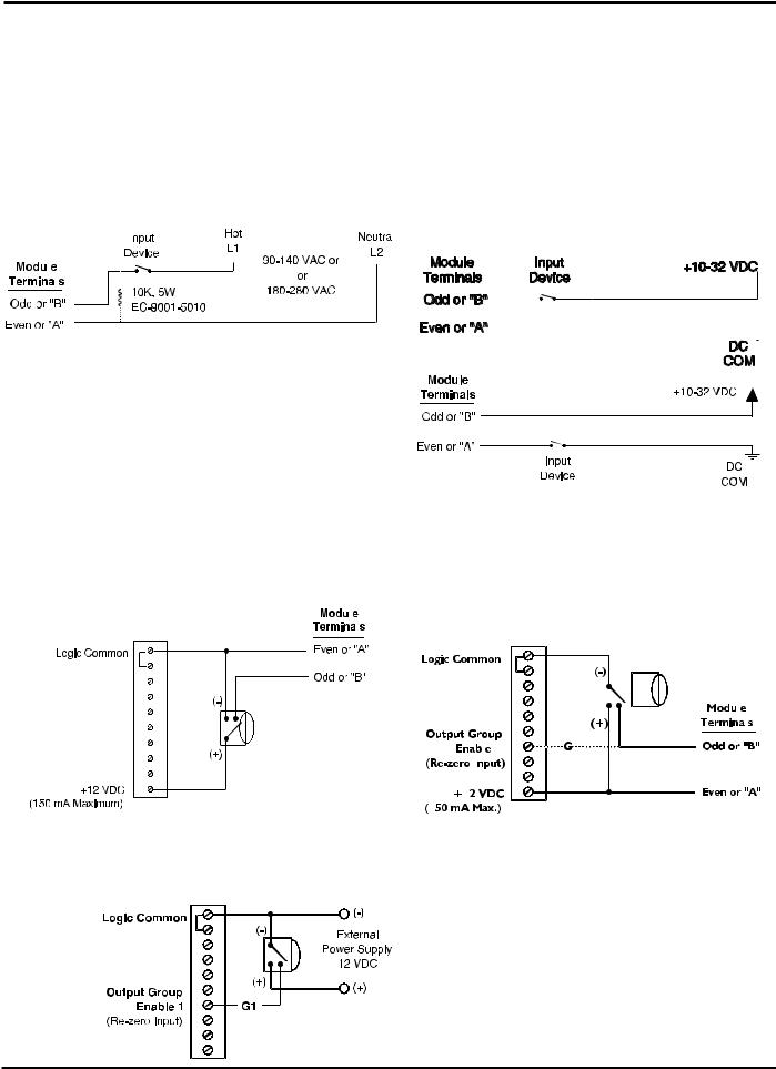
Module Wiring—Inputs
|
|
|
AC Input |
|
|
|
|
|
|
|
DC Input |
PS-5024 |
|||
|
|
|
|
|
|
|
|
|
|
|
Sourcing |
PS-5124 |
|||
|
|
|
|
|
|
|
|
|
|
|
|||||
|
|
|
|
|
|
|
|
|
|
|
|||||
|
|
|
|
|
|
|
|
|
|
|
|
|
|
|
|
|
|
|
|
|
|
|
|
|
|
|
|
|
|
|
|
|
|
|
|
|
|
|
|
|
|
|
|
|
|
|
|
|
|
|
|
|
|
|
|
|
|
|
|
|
|
|
|
|
|
|
|
|
|
|
|
|
|
|
|
|
|
|
|
|
|
|
|
|
|
|
|
|
|
|
|
|
|
|
|
|
|
|
|
|
|
|
|
|
|
|
|
|
|
|
|
|
|
|
|
|
|
|
|
|
|
|
|
|
|
|
|
|
|
|
|
|
|
|
|
|
|
|
|
|
|
|
|
• Input devices can be mechanical contacts or solid state.
•The load 10K load resistor shown may be needed if the AC input device has off-state leakage, such as a solid state triac.
Sinking
•Input devices can be mechanical contacts or solid state.
•12 VDC power is available from the controller’s logic terminal strip. See page 3-1 for details.
Input Wiring, 3-Wire Sensors
Using Logic Terminal Strip Power Supply (pg. 3-1) |
Various |
|||||||||||||||||
Sourcing |
|
|
|
|
|
|
|
|
Sinking |
Models |
||||||||
|
|
|
|
|
|
|
|
|||||||||||
|
|
|
|
|
|
|
|
|
|
|
|
|||||||
|
|
|
|
|
|
|||||||||||||
|
|
|
|
|
|
|
|
|
|
|
|
|
|
|
|
|
|
|
|
|
|
|
|
|
|
|
|
|
|
|
|
|
|
|
|
|
|
|
|
|
|
|
|
|
|
|
|
|
|
|
|
|
|
|
|
|
|
|
|
|
|
|
|
|
|
|
|
|
|
|
|
|
|
|
|
|
|
|
|
|
|
|
|
|
|
|
|
|
|
|
|
|
|
|
|
|
|
|
|
|
|
|
|
|
|
|
|
|
|
|
|
|
|
|
|
|
|
|
|
|
|
|
|
|
|
|
|
|
|
|
|
|
|
|
|
|
|
|
|
|
|
|
|
|
|
|
|
|
|
|
|
|
|
|
|
|
|
|
|
|
|
|
|
|
|
|
|
|
|
|
|
|
|
|
|
|
|
|
|
|
|
|
|
|
|
|
|
|
|
|
|
|
|
|
|
|
|
|
|
|
|
|
|
|
|
|
|
|
|
|
|
|
|
|
|
|
|
|
|
|
|
|
|
|
|
|
|
|
|
|
|
|
|
|
|
|
|
|
|
|
|
|
|
|
|
|
• For controllers using input/output modules.
•Module wiring applies only to controllers using input/output modules.
•Using sensor to switch terminal 7 can be done for any PS-5000 Series controller. See page 3-1 for details.
Using External Power Supply & Terminal 7
• Using sensor to switch terminal 7 can be done for any PS-5000 Series controller. See page 3-1 for details.
3-5 Wiring

Built-In Transistor I/O Chips: Specifications
PS-5011
PS-5111
The output board which contains the output transistor array chips and the fuse(s) is located under the output board cover. The pluggable output terminal strips plug into receptacles that are mounted to the output board The only time it will be necessary to remove the output board cover is when an output fuse is blown or a transistor array chip is damaged.
Output Transistor Array Chips:
Each group of 8 output transistors is contained in a single 18 pin transistor array chip. If one or more of these transistors becomes damaged, the chip can simply be unplugged from the socket and replaced. Note that Sinking and Sourcing output boards do not use the same transistor array chip.
Output Fuses:
Each group of 8 outputs (1 transistor array chip) is protected by a 1 Amp plug in fuse. This fuse will blow if the DC power polarity is incorrectly wired to the “+” and “-” terminals on the output terminal strip. On the sourcing output versions this fuse will also blow if the total amount of current being
conducted by that group of 8 outputs exceeds 1 Amp. If a fuse blows, all 8 of the outputs in that group will be inoperative until the fuse is replaced.
Output Cables:
Pluggable screw terminal strips are used to connect the transistor outputs to the load device. Therefore, no special connectors are needed for output wiring. However, shielded cable is recommended (Electro Cam part #: PS-4300-04- XXX, 2 cables required for systems with more than 8 outputs) to maximize immunity to electrical noise. The shield should be connected to the grounding screw located on the back panel just above the output terminal strips. The shield should be unconnected at the load end of the cable. Also, the cable should be kept away from other electrical wiring, especially control wiring involving solenoids, relays, contactors, and motors.
3-6 Wiring

Built-In Transistor I/O Chips: Output Wiring, Sourcing
PS-5011
PS-5111
The output power supplies shown can be internal to the load device being driven. This will normally be the case when connecting to PLC's.
The loads connected to outputs 1-8 must all be powered from the same power supply.
The loads connected to outputs 9-16 must all be powered from the same power supply.
The same power supply can be used to power all 16 outputs by paralleling the wiring between the “+” and “-” terminals on the PLμS output terminal strips.
The load power supply must be connected to both the “+” and “-” terminals on the output terminal strip(s).
The unpluggable output terminal strips are keyed so they can only be plugged into the correct receptacle.
Use shielded cable(s) for output wiring. Electro Cam 10 conductor cable part number PS-4300-04-XXX (XXX=length in feet) is recommended. Two cables required for 16 output units.
3-7 Wiring

Built-In Transistor I/O Chips: Output Wiring, Sinking
PS-5011
PS-5111
The output power supplies shown can be internal to the load device being driven. This will normally be the case when connecting to PLC's.
More than 1 power supply can be used to power loads within each group of 8 outputs. Only one of the power supplies used within the group can have its positive side connected to the “+” terminal of the corresponding 5011 output terminal strip. The common of each power supply used within a group of 8 outputs must be connected to the “-” terminal of the output terminal strip.
The same power supply can be used to power all 16 outputs by paralleling the wiring between the “+” and “-” terminals on the 5011 output terminal strips.
Both the “+” and “-” terminals on the output terminal strip(s) must be connected to a load power supply.
The unpluggable output terminal strips are keyed so they can only be plugged into the correct receptacle. Do not force when plugging them in.
Use shielded cable(s) for output wiring. Electro Cam 10 conductor cable part# PS-4300-XXX (XXX=length in feet) is recommended. Two cables required for 16 output units.
3-8 Wiring
Built-In Transistor I/O Chips: Output Wiring to PLC
PS-5011
PS-5111
PS-5X11 with
PLC with Sinking Inputs
Sinking Outputs
(A.B. calls these sourcing inputs)
 Power Supply can be external from the PLC.
PS-5X11 with
Sourcing Outputs
PLC with Sourcing Inputs
(A.B. calls these sinking inputs)
Power Supply can be  external from the PLC.
3-9 Wiring

PS-5X34 Controller & 32 DC Output Rack
Introduction
The PS-5X34 system is available with either 32 or 64 low current transistor outputs. These systems are intended to be interfaced directly to PLCs or other control devices with low level DC inputs.
The 32 transistor output rack(s) used with PS-5X34 controls can be DIN rail mounted (-D) or foot mounted (-F) and are available with Sinking or Sourcing outputs.
Systems that require 32 or fewer outputs will only need one of the transistor output racks. Systems requiring more than 32 outputs need two transistor output racks daisy chained together (see rack configuration section below).
The PS-5X34 controller incorporates the same keyboard and features that other PS-5000 controls use. Because of the large number of outputs being controlled, the number of programs stored in a 32 output controller is 32, and the number of programs in a 64 output controller is 16.
This control has PS-5XX4 capabilities (output grouping and modes) and includes an RS-232/485 communications port. Outputs can be subdivided into as many as 8 groups, and the position of each of these groups can be offset individually. Because the rack transistor outputs cannot be configured as inputs, the only enable input available is the "Output Group Enable 1" input located on the logic strip. Output Group 1 can operate in any output mode, all other groups must operate in Mode 0 only.
PS-4100-12-X32-X Dimensioned Drawing
|
|
|
DIN Rail Mount* |
1/2" (13mm) |
|
Foot Mount |
3" |
|
(76mm) |
||
|
|
||
|
|
|
|
|
9" |
2-1/2" |
|
|
(229mm) |
2-13/16" |
|
|
(64mm) |
||
|
1/4" (6mm) |
(72mm) |
|
7/8" |
|
||
|
|
||
|
|
|
|
(22mm) |
|
|
|
C |
|
3-1/8" |
|
L |
|
(79mm) |
|
|
|
|
0.168" (4.3mm) |
Brackets (2) on |
DIN Rail |
DIN Rail |
|
For #8 Screw |
EN 50022 |
|||
Foot Mount Version (-F) Only |
||||
|
|
EN 50035 |
*DIN Rails must be ordered separately
Output Rack Configuration
Control systems requiring 32 or fewer outputs will need only |
To PS-5X34 Control |
1 PS-4100-12-X32 transistor output rack. The "Rack |
|
Address Jumper" must be plugged into position 1. This will |
|
configure the outputs to be channels 1-32. 1 rack cable (Pt# |
|
PS-4300-02-XXX) will be needed to connect the rack to the |
|
controller. |
|
Control systems requiring more than 32 outputs will need 2 PS-4100-12-X32 transistor output racks. The "Rack Address Jumpers" must be plugged into position 1 on one of the racks, and position 2 on the other. Output channel numbers will be assigned as shown in the illustration to the right. 2 rack cables (Pt# PS-4300-02-XXX) will be needed: one to connect the controller to the first rack and the other to connect the two racks.
3-10 Wiring

PS-5X34 System: Output Rack Layout
Sinking Output Rack Pt#: PS-4100-12-N32
Each Output can Sink 3-30 VDC, 100 mA Max
DB 25 Connectors (Female)
Connect to PLuS controller or another rack
(these connectors can be used interchangeably)
Sourcing Output Rack Pt#: PS-4100-12-P32
Each Output can Source 10-30 VDC, 100 mA Max
PLμS Power LED
On when PLμS control is powered up and connected to rack
Output Terminals
25-32
E.C. Pt#: PS-9006-0014
(unpluggable)
Output Terminals
17-24
E.C. Pt#: PS-9006-0013
(unpluggable)
|
|
|
|
|
Rack Address Jumper |
|
|
|
|
|
1: Channels 1-32 |
|
|
|
|
|
2: Channels 33-64 |
|
|
|
|
|
3: Unused |
|
|
|
|
|
4: Unused |
|
|
|
|
|
(Jumper shown in position 1) |
|
|
|
|
|
Transistor Array Chips |
|
|
|
|
X |
(socketed for field replacement) |
|
|
|
|
E.C. Pt#: PS-9011-2803 |
|
|
|
|
|
|
|
|
|
|
|
|
Generic Pt#: ULN-2803 |
|
|
|
|
|
Output Terminals 1-8 |
|
|
|
|
|
E.C. Pt#: PS-9006-0011 |
|
|
|
|
|
(unpluggable) |
Y |
|
X |
Y |
|
Transistor Array Chips on |
X |
|
Sourcing Output Racks |
|||
|
|
|
|
|
(socketed for field replacement) |
|
|
|
|
|
E.C. Pt#: PS-9011-2580 |
|
|
|
|
|
Generic Pt#: UDN-2580 |
|
Y |
OR |
|
|
Dip Jumper Blocks on |
|
|
Sinking Output Racks |
|
|
E.C. Pt#: PS-9006-0015 |
Y X |
X Y |
Output Terminals 9-16 |
|
|
E.C. Pt#: PS-9006-0012 |
|
|
(unpluggable) |
|
|
User DC Power Input |
F1 |
F2 |
10 - 30 VDC, 4 Amp Max |
(Sinking outputs switch "-") |
||
|
|
(Sourcing outputs switch "+") |
|
|
User DC Power Fuses |
User Power LED |
|
4 Amps (F1= "+", F2="-") |
On when user power applied to rack |
E.C. Pt#: PS-9005-0004 |
|
(will NOT be on if user power fuse is blown) |
Wickman Pt#: 19370-K |
|
3-11 Wiring

PS-5X34 System: Wiring to PLCs
Wiring to a PLC with Sinking Inputs
(A.B. calls these Sourcing Inputs)
PS-4100-12-N32 |
Note: |
|
PLμS transistor output rack and PLC MUST both be connected to the same DC positive.
PLC
 Power Supply can be external from the PLC
Wiring to a PLC with Sourcing Inputs
(A.B. calls these Sinking Inputs)
PS-4100-12-P32
Note: PLμS transistor output rack and PLC MUST both be connected to the same DC common.
PLC
Power Supply can be external from the PLC
3-12 Wiring
Loading...