

Page 1
PL µS® PS-6 144 Series
Programmable Limit Switch
6000
PGM:1 RPM:1500
MENU< POS: 180
Series
Programming &
Installation Manual
October 2001
13647 Metric Rd • Roscoe, IL 61073 USA • 815/389-2620 • FAX 815/389-3304 • 800-228-5487 (U.S.A. and Canada)
Page 2

Copyright © 2001
All Rights Reserved
Neither this document nor any part may be reproduced or transmitted in
any form or by any means without permission in writing from the publisher.
®
, PLµS®, SLIMLINE®, and PLµSNET® are all registered trademarks of
Page 3

Table of Contents
Section 1—Introduction
Mechanical Cam Switches .............1-1
Programmable Limit Switches........1-1
PS-6144 Description ......................1-2
Basic Terminology..........................1-3
PS-6144 Standard Features ..........1-3
PS-6144 Optional Features............1-4
Section 2—Installation & Wiring
General Mounting & Wiring ............2-1
Mounting Dimensions.....................2-2
Terminals & Components
PS-6144-24M17 ........................2-3
PS-6144-24-X16-M09 ...............2-4
Controller Input Wiring ...................2-5
Output Wiring .................................2-8
Keypad Wiring................................2-12
DIP Switch Configurations .............2-13
Communications Wiring .................2-15
Resolver Installation .......................2-16
Resolver Dimensions .....................2-17
Resolver Cables.............................2-18
Fuse Tester & Fuse Replacement .2-19
Output Transistor Replacement .....2-20
Section 3—Programming
Keypad Overview ...........................3-1
Menu Tree......................................3-2
Initial Programming ........................3-3
Functions (Alphabetically)
Analog Output ...........................3-4
Analog Quantity.........................3-5
Channel Copy............................3-6
Communications........................3-6
Default Program ........................3-7
Enable Codes............................3-8
Enable Options..........................3-10
Group Position Display..............3-10
Increasing Direction...................3-11
Input Status ...............................3-12
Keyboard Quantity.....................3-12
Main Screen ..............................3-13
Memory Tests............................3-14
Motion ANDing ..........................3-14
Motion Detection .......................3-15
Offset.........................................3-16
Output Enable ANDing ..............3-18
Output Groups...........................3-18
Output Status ............................3-19
Password...................................3-20
Per Channel Enable ..................3-21
Program Copy ...........................3-21
Program Select Mode................3-22
Pulse Copy ................................3-22
Rate Setup ................................3-24
Resolver Type ...........................3-25
RPM Update Rate .....................3-25
Scale Factor ..............................3-25
Setpoint Use..............................3-26
Setpoints ...................................3-26
Shaft Position ............................3-28
Software Version .......................3-28
Speed Compensation................3-28
Speed Comp Mode ...................3-29
Timed Outputs...........................3-30
Toggle RPM ..............................3-30
Section 4—Speed Compensation
Introduction ....................................4-1
Examples .......................................4-2
Leading/Trailing Speed Comp........4-4
Negative Speed Comp ...................4-6
Programming Guidelines................4-6
Section 5—Output Grouping & Modes
Introduction ....................................5-1
Mode 0 ...........................................5-3
Mode 1 ...........................................5-3
Mode 2 ...........................................5-4
Mode 3 ...........................................5-5
Mode 4 ...........................................5-6
Mode 5 ...........................................5-7
Speed Comp & Modes ...................5-8
Section 6—Communications
PLuSNET II Program .....................6-1
Serial Communications Using
Electro Cam Corp. Protocol ...........6-3
Error Codes ....................................6-12
Checksum Calculations..................6-12
Serial Communications Using
Modbus ASCII Protocol..................6-13
Section 7—Troubleshooting
Controller Diagnostics ....................7-1
Keypad Diagnostics .......................7-2
Resolver Troubleshooting ..............7-3
General Troubleshooting................7-4
Fuse Part Numbers ........................7-6
Appendix
Controller Specifications ................A-1
Slimline Module Specifications.......A-2
Transistor Output Specifications ....A-3
Resolver Specifications..................A-3
Factory Defaults .............................A-3
PS-6144 Setpoint Record ..............A-4
Index
Page 4

WARRANTY
1. Electro Cam Corp. warrants that for a period of twelve (12) months from the date of shipment to
the original purchaser, its ne w product to be free from defects in material and workmanship and
that the product conforms to applicable drawings and specifications approved by the Manufacturer. This warranty period will be extended on Distributor or OEM orders to a maximum of
eighteen months to take into consideration Distributor or OEM shelf time.
2. The remedy obligations of Electro Cam Corp. under this warranty are exclusive and are limited to
the repair, or at its option, the replacement or refund of the original purchase price of any new
apparatus which proves defective or not in conformity with the drawings and specifications. Shipment of the claimed defectiv e product to Electro Cam Corp. shall be at the cost of the consumer.
Shipment of the repaired or replacement product to the consumer shall be at the cost of Electro
Cam Corp. All claims must be made in writing to Electro Cam Corp., 13647 Metric Road, Roscoe,
IL 61073 USA.
3. In no event, and under no circumstances, shall Electro Cam Corp. be liable for:
a. Any product damaged or lost in shipment. Inspection for damage should be made before
acceptance or signing any delivery documents releasing responsibility of the delivering carrier.
b. Product failure or damages due to misuse abuse, improper installation or abnormal condi-
tions of temperature, dirt or other contaminants as determined at the sole discretion of Electro
Cam Corp.
c. Product failures due to operation, intentional or otherwise, above rated capacities as deter-
mined at the sole discretion of Electro Cam Corp.
d. Non-authorized expenses for removal, inspection, transportation, repair or rework. Nor shall
the manufacturer ever be liable for consequential and incidental damages, or in any amount
greater than the purchase price of the equipment.
4. There are no warranties which extend beyond the description on the face hereof. This warranty
is in LIEU OF ALL OTHER WARRANTIES, EXPRESSED OR IMPLIED INCLUDING (B UT NOT
LIMITED T O) ANY IMPLIED WARRANTIES OF MERCHANTABILITY OR FITNESS FOR A PARTICULAR PURPOSE, ALL OF WHICH ARE EXPRESSLY DISCLAIMED. Any legal proceeding
arising out of the sale or use of this apparatus must be commenced within (18) months of the date
of shipment from the manufacturer.
Page 5
Mechanical Cam Switches
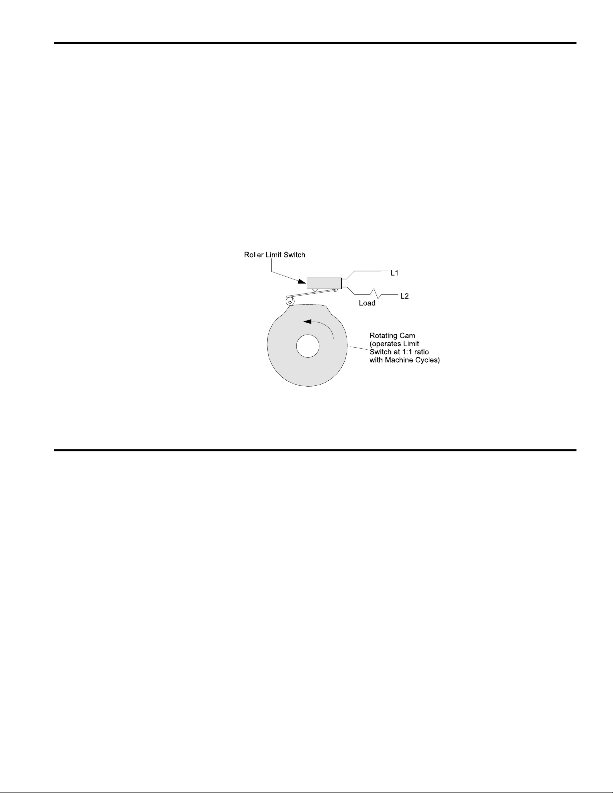
Mechanical Cams The PS-6144 Programmable Limit Switch electronically simulates mechanical cam
switches. A cam switch consists of a roller limit switch whose arm rides on a cam as
shown in Figure 1. The cam shaft is driven by a machine at a 1:1 ratio, so that the cam
switch turns on and off at specific positions in the machine cycle. Cam limit switches
have the following disadvantages:
• The roller, the cam, and the limit switch wear out.
• The machine must be stopped during adjustment.
• On/off patterns are limited, and changing the pattern may require replacement of one
cam with another. For example, a cam that switches on and off twice in one revolution would need to be replaced with a different cam if three on/off pulses per revolution were required.
• They cannot run at high speeds because of contact bounce and excessive mechanical wear.
Figure 1—Basic Cam Switch
Programmable Limit Switches
PS-6144’s & Resolvers The PS-6144 Programmable Limit Switch uses a resolver (see Figure 2 on page 2)
instead of a cam to indicate machine position. A resolver uses fixed and rotating coils of
wire to generate an electronic signal that represents shaft position. The resolver is
usually coupled to a machine shaft at a 1:1 ratio so that one resolver shaft rotation
corresponds to one machine cycle. Resolvers have no brushes, contacts, or any frictional moving parts to wear out.
Based on the resolver signal, the PS-6144 Programmable Limit Switch turns electrical
circuits, or “Outputs,” on and off, simulating the mechanical roller limit switch. Because
the combination PS-6144/resolver system is completely electronic and has no frictional
parts, it offers several advantages over mechanical cam switches:
• Long service life with no parts to wear out.
• “On” and “off” points can be adjusted instantly from the keypad; there are no cams to
rotate or replace.
• Adjustment is possible with the machine running or stopped.
• Programmable logic allows complex switching functions that are impossible with
mechanical cams.
• Operation at speeds up to 3000 RPM.
1-1 Introduction
Page 6
Programmable Limit Switches
PS-6144
Controller
PS-6000 Series
Keypad/Display
Electro Cam Corp.
Foot Mount Resolver
With Side/Top Connection
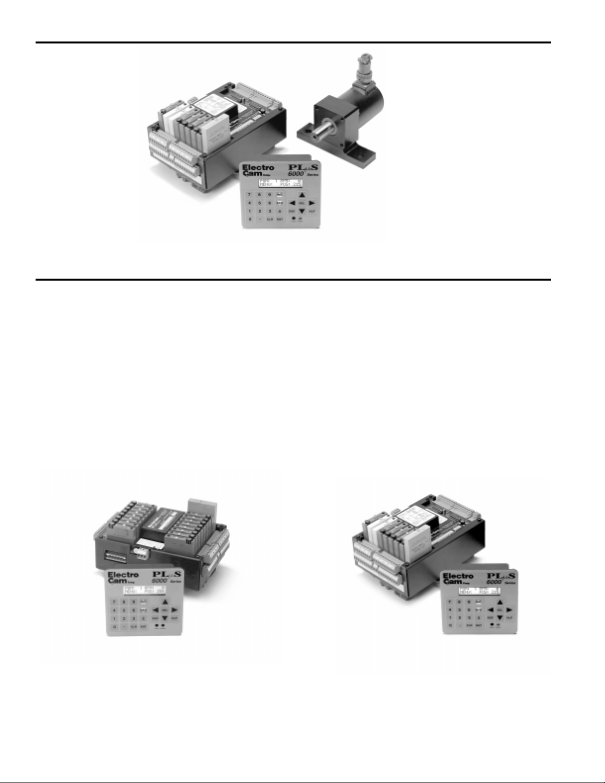
Figure 2—PS-6144 Programmable Limit Switch and Resolver
PS-6144 Description
Controller & Keypad PS-6144 Series Programmable Limit Switches consist of two main components, the
controller and the keypad/display. The controller houses the microprocessor, associated circuitry, and all of the I/O circuits. This eliminates the need for external I/O racks.
A separate 1/4 DIN keypad/display provides a complete user interface from which every aspect of the controller’s operation can be monitored and programmed. Multiple
keypads can be connected to a single controller. In addition, when interfaced to a PLC
or other computer, the controller can be used without a keypad/display. When properly
mounted with the gasket provided, the keypad/display meets NEMA 4 standards. A
clear silicon rubber boot assembly is available to provide NEMA 4X protection for installations where harsh washdown chemicals are used.
The PS-6144 Series is available in two models, the PS-6144-24-X16-M09 and the PS6144-24M17. Both are described in Figure 3.
PS-6144-24M17 Controller—Up to 17 Outputs
The PS-6144-24M17 has 17 total outputs:
• Outputs 1 through 17 can accept AC or DC output
modules for driving “real world” devices such as
solenoids, valves, or glue guns.
• Outputs 16 & 17 will also accept an analog module
that generates a control signal proportional to RPM.
Figure 3—PS-6144 Models
1-2 Introduction
PS-6144-24-X16-M09 Controller—Up to 25
Outputs
The PS-6144-24-X16-M09 has 25 total outputs:
• 16 transistor outputs are built into the controller.
• Outputs 17 through 25 can accept AC or DC output
modules for driving “real world” devices such as
solenoids, valves, or glue guns.
• Outputs 24 & 25 will also accept an analog module
that generates a control signal proportional to RPM.
Page 7

Basic T erminology
The following terms will be used throughout this manual to explain PS-6144 installation,
programming and operation:
Channels Each Channel (CHN) in the PS-6144 controller contains “on” and “off” setpoints for one
360° revolution of the resolver shaft. Channels are one of two types:
Output Channels—These channels use a switching transistor or an output module to
turn an external circuit on or off. One or two output channels in a controller may also
use an analog output module to generate a control signal that is proportional to RPM.
Group Channels—These channels control the interaction between groups of outputs
and an input received from a sensor or other controlling device. See Section 5 for
details on Group Channels.
Setpoints “Setpoints” are the points within one rotation of the resolver at which a channel turns on
or off. Setpoints can be programmed into a channel through the keypad/display, or they
can be downloaded from a computer or PLC through serial communications. The PS6144 can turn any given channel on and off multiple times within one rotation.
Pulses A “pulse” is the “on” period between the time a channel is turned on and off. The “on”
setpoint is the leading edge of the pulse, and the “off” setpoint is the trailing edge.
When multiple pairs of setpoints are programmed into one channel, the channel is said
to have multiple pulses.
Programs Suppose that 15 output channels on a cartoner are programmed with setpoints to fold
and glue a certain size carton. These settings could be stored as a “program.” The 15
output channels could then be re-programmed with different setpoints for a different
size carton. This second set of setpoints could also be stored as a program. To change
carton sizes, an operator could simply activate the correct program, and the corresponding setpoints would take effect.
Standard PS-6144’s can store up to 48 programs. The active program can be selected
through the keypad/display, mechanical switches, direct PLC interface, or serial communication messages.
Inputs (hardware inputs) In addition to accepting a signal from the resolver, the PS-6144 can accept up to 16
input signals from mechanical switches, relay contacts, DC two- or three-wire sensors,
solid state DC output modules, or PLC DC outputs. The PS-6144 hardware inputs are
dedicated to specific functions involving program selection and controlling output channels based on sensor signals.
Groups and Modes Output channels can be combined into “groups”, and each group can be associated
with an input terminal in any of six different “modes” of operation. For example, some
modes activate the group only when the corresponding input has signaled that product
is present. Glue control is a typical application where outputs are disabled until product
is sensed. See Section 5 for details.
PS-6144 Standard Features
Scale Factor The user can program the number of increments per revolution, or “Scale Factor.” For
example, to make the controller display position in degrees, a Scale Factor of 360 is
used. For some applications, Scale Factor may be set to define increments in terms of
linear distance, such as one increment equals 0.1" of travel. Standard controls have a
maximum of 1024 increments per revolution, while “-H” option (high resolution) controls
have a maximum of 4096 increments per revolution.
Programming Access Three levels of programming access are provided: Operator, Setup, and Master. Each
level can be assigned a password that must be entered to allow programming at that
level. In addition, the Operator and Master levels can be activated on an individual
keypad through hardware terminals on the back. Careful use of programming access
levels can provide key personnel the flexibility they need in programming the controller,
while protecting settings against accidental or unauthorized changes.
1-3 Introduction
Page 8

PS-6144 Standard Features (Cont'd)
Speed Compensation Speed compensation advances the setpoints for an output as machine speed increases.
This eliminates the need to manually adjust the setpoints for fixed-response devices
when machine speeds are changed. Speed compensation provides greater accuracy,
higher production speeds, and reduced downtime for machine adjustment.
Motion ANDing Two speed ranges can be programmed into the controller, and outputs can be ANDed
with either speed range so that they will be disabled unless the machine speed is within
the range. A common use for this feature is disabling outputs to glue valves to turn off
glue flow if the machine stops.
Timed Outputs Timed outputs are programmed like standard outputs to turn on and off at specific
points of resolver rotation. However, once a timed output is on, it will remain on for a
specified time period, regardless of RPM. If the programmed “off” position is reached
before the time period passes, the output will turn off. Timed outputs are used to drive
devices such as pneumatic cylinders which require a fixed time to perform a task, regardless of machine speed.
Analog Outputs PS-6144 controllers can drive two analog output modules whose output signals will be
linearly proportional to RPM. The analog signal level at zero RPM can be programmed,
as well as the RPM that corresponds to maximum signal. No measuring equipment is
required for initial setup, and calibration is not needed. Typical uses for the analog
output are to control glue pressure as machine speeds change, or to match speeds of
other equipment to the machine being controlled by the PS-6144.
Serial Communication Using Electro Cam Corp.’s PLuSNET software for IBM-PC compatible computers, the
controller’s entire program can be saved to a disk file or loaded from a disk file to the
controller. The program can be printed or edited using the computer. Individual commands may also be sent to the controller to change settings while running.
PS-6144 Optional Features
(-F) Large Program Memory Depending on the number of outputs used, standard controls can store 48 programs
consisting of not more than 1258 total output pulses. Controls with the “-F” option can
store up to 256 programs consisting of not more than 4589 output pulses.
(-G) Gray Code Output This option provides eight bits of position information on outputs one through eight.
This “gray code” output can provide position information to a PLC or other electronic
control device without the use of expensive PLC accessory cards. The PLC can then
make control decisions that do not demand a fast response, while other PLuS outputs
directly control devices that must operate accurately at high machine speeds.
(-G10) Gray Code Output This option provides ten bits of position information on outputs one through ten.
(-H) High Resolution Controls with this option can divide one resolver revolution into as many as 4096 incre-
ments. Standard controls use 1024 increments maximum. The “-H” Option allows higher
Scale Factors to be used. For example, a Scale Factor of 3600 would allow programming in 0.1 degree increments. Or, for an application in which one revolution equals 24"
of linear travel, a Scale Factor of 2400 would result in increments equal to .01" of travel.
(-L) Leading/Trailing The “-L” option allows the “on” and “off” edges of output pulses to be
Edge Speed Comp speed compensated by different amounts. This option is used for devices whose “on”
and “off” response times are significantly different. High speed gluing is a common
application requiring separate leading/trailing edge speed compensation. See Section
4 for details.
(-MSV) Master/Slave Master/Slave resolver mode for multiple controllers used with one resolver.
(-MB) Modbus™ Modbus™ ASCII protocol for serial communications.
(-V) Vibration Coating Vibration protective coating for extra protection against shock and vibration.
(-W) Washdown Boot Keypads with the “-W” option are rated NEMA 4X and are shipped with a clear silicon
rubber boot fitted over and around the keyboard area. In addition to preventing contamination from harsh chemicals, the boot also protects the keyboard from grease, oil,
dirt and normal wear that could otherwise shorten the life of the keyboard.
1-4 Introduction
Page 9

General Mounting & Wiring
Controller The controller body mounts on a DIN rail as shown in Figure 4.
Keypad/Display Mount the keypad/display to a panel using the four studs on the back of the keyboard.
Enclosures are available from Electro Cam if an appropriate mounting location does
not exist.
DIP Switches For convenience, set the DIP switches on the side of the controller and keypad to
their proper positions before mounting the units in a panel. See page 2-13 for DIP
switch information.
Environment 1. Allow space at both sides and the top of controller for terminal blocks to be un-
plugged.
2. Ambient temperature range is 0° to 55°C (32° to 130°F).
3. Locate the controller and keypad away from devices that generate electrical noise,
such as contactors and drives.
4. Use the keypad/display gasket provided to prevent contaminants from getting into
the cabinet.
Terminal Blocks All terminal blocks can be unplugged from the controller. Each block is keyed so it
cannot be plugged into the wrong socket. All terminals are labelled on each block.
Wiring Guidelines Follow normal wiring practices associated with the installation of electronic controls.
Some guidelines are:
CAUTION
1. Route input and output wiring away from high voltage, motor drive, and other high
level control signals.
2. Use shielded cables for resolver, input, transistor output, and communication circuits. Also shield module output circuits that are driving low current electronic input
circuits.
3. Ground shielded cables at the PS-6144 end only (except for resolver cable). Use
any of the screws on the controller back for grounding.
4. Use appropriate suppression devices where module outputs are directly driving inductive loads.
Power Supply Wiring Connect a 20 to 30 VDC power supply to TB 8 (Fig. 5 or 6). Reversing the polarity will
blow the 1-1/4 amp power fuse. The controller will not be damaged, but you must correct the polarity and replace the fuse before the controller will operate.
To insure electrical noise immunity, connect a good electrical ground to the ground
terminal on the power supply terminal block.
Module Mounting A phillips head screw holds each module in place. Individual modules can be removed
and installed without affecting the other modules on the unit.
Disconnect power to the controller before changing modules.
2-1 Installation & Wiring
Page 10
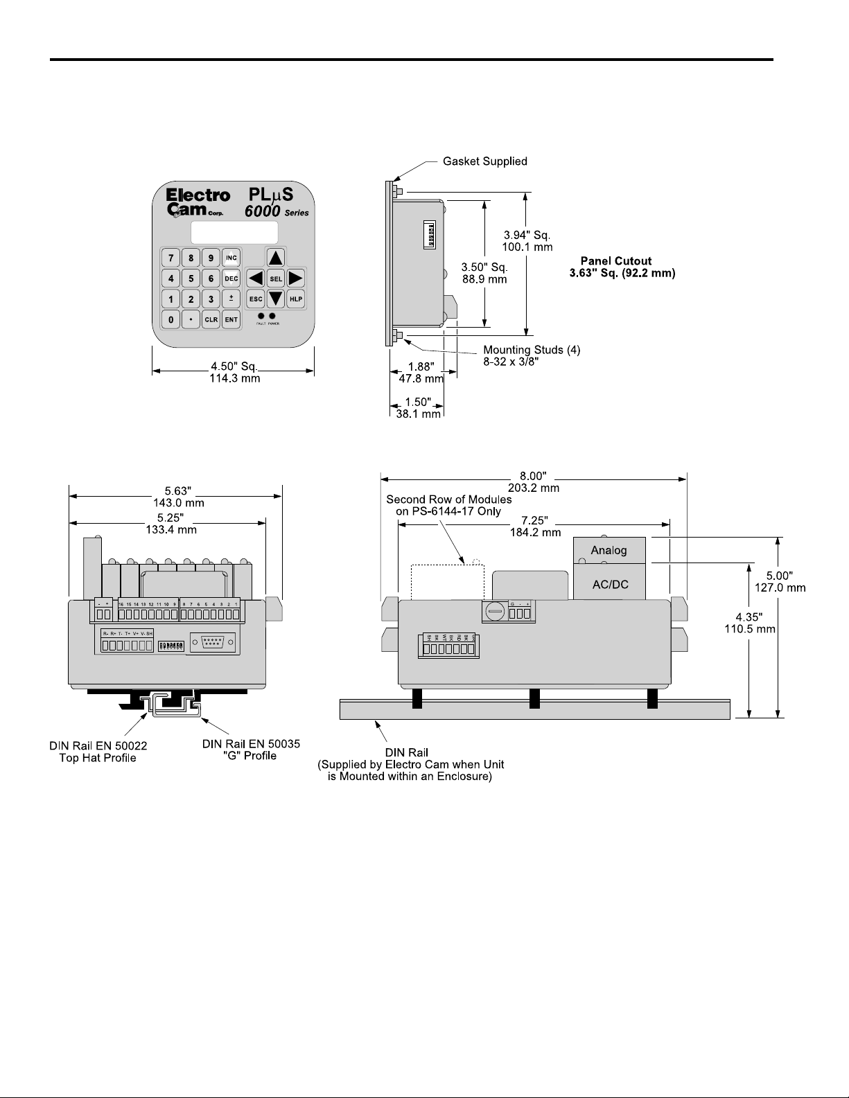
Mounting Dimensions
Figure 4—Mounting Dimensions
PGM:1 RPM:1500
MENU< POS: 180
2-2 Installation & Wiring
Page 11
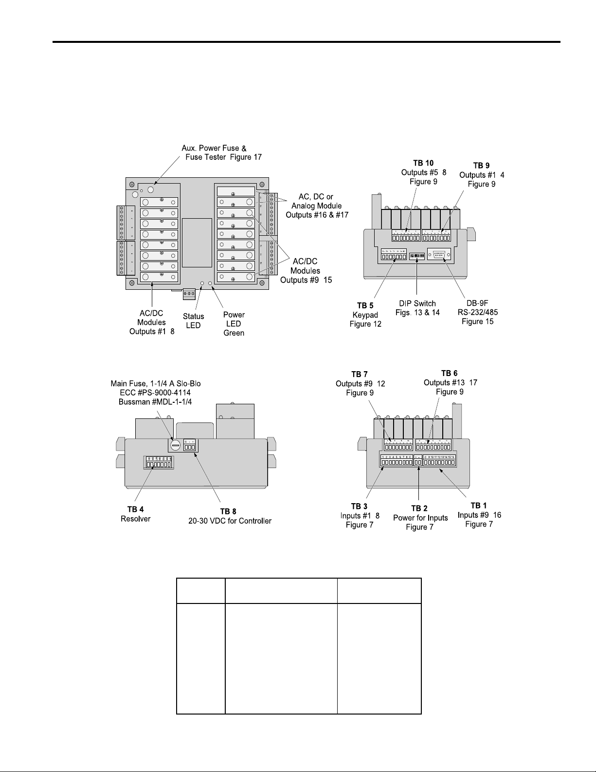
Terminals & Components—PS-6144-24M17
Figure 5—PS-6144-24M17 Terminals & Components
Top View
-
Yellow
Front View
Left Side View
-
-
-
Right Side View
-
-
-
Terminal Block Details
Terminal
Block Function ECC Part #
TB 1 Inputs #9–16 PS-9006-0024
TB 2 Auxiliary power output PS-9006-0018
TB 3 Inputs #1–8 PS-9006-0023
TB 4 Resolver connector PS-5300-01-TER
TB 5 Keypad port connector PS-9006-0029
TB 6 Module outputs #13-17 PS-9006-0031
TB 7 Module outputs #9-12 PS-9006-0030
TB 8 Power for controller PS-9006-0026
TB 9 Module outputs #1-4 PS-9006-0033
TB 10 Module outputs #5-8 PS-9006-0034
1
Keyed to prevent accidental insertion into wrong sockets.
-
1
2-3 Installation & Wiring
Page 12
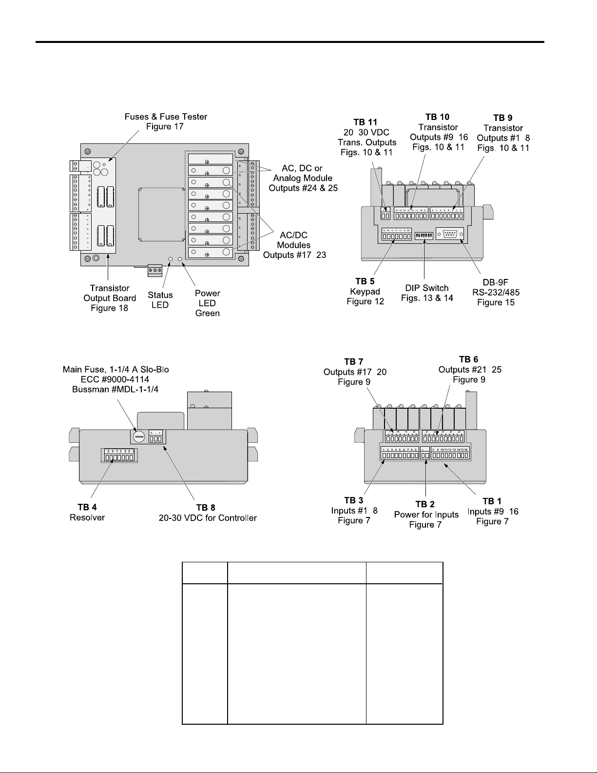
Terminals/Components PS-6144-24-X16-M09
Figure 6—PS-6144-24-X16-M09 Terminals & Components
Top View
Y ello w
Front View
Left Side View
-
-
-
-
Right Side View
-
-
2-4 Installation & Wiring
-
Terminal Block Details
Terminal
Block Function ECC Part #
TB 1 Inputs #9–16 PS-9006-0024
TB 2 Auxiliary power output PS-9006-0018
TB 3 Inputs #1–8 PS-9006-0023
TB 4 Resolver connector PS-5300-01-TER
TB 5 Keypad connector PS-9006-0029
TB 6 Module outputs #21–25 PS-9006-0028
TB 7 Module outputs #17–20 PS-9006-0027
TB 8 Power for controller PS-9006-0026
TB 9 Transistor outputs #1–8, sinking PS-9006-0019
TB 10 Transistor outputs #9–16, sinking PS-9006-0020
TB 11 Power for transistor outputs PS-9006-0017
1
Keyed to prevent accidental insertion into wrong sockets.
Transistor outputs #1–8, sourcing PS-9006-0021
Transistor outputs #9–16, sourcing PS-9006-0022
-
1
Page 13

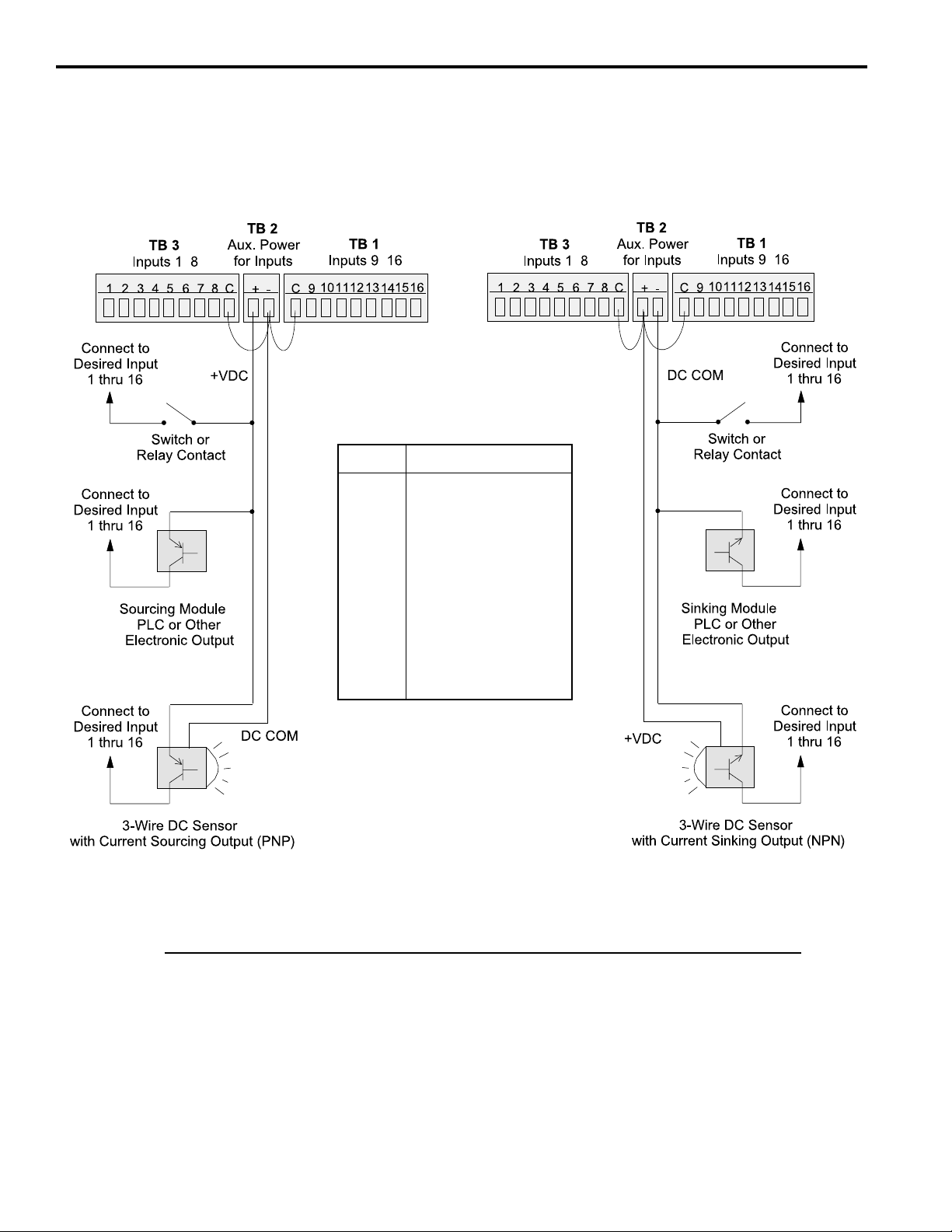
Controller Input Wiring
Input Terminals Hardware inputs can be used to select a program of setpoints or activate groups of
outputs based on sensor signals according to mode logic as described in Section 5.
The 16 inputs on the PS-6144 are arranged on two terminal strips, TB 1 and TB 3, as
shown in Figure 7. Each input is optically isolated and can be powered from an external
DC power source or the Auxiliary Power terminals located on TB 2.
Sinking or Sourcing Each terminal strip TB 1 and TB 3 can be wired to accept sinking or sourcing input
signals, but all eight inputs on that strip will require the same type of signal. Many types
of hardware can drive these inputs, including mechanical switches, relay contacts, DC
3-wire sensors, solid state DC output modules, and PLC DC outputs. 2-wire DC sensors can also be used, but may require a load resistor in parallel with the input. Typical
wiring diagrams are shown in Figure 7.
Input Functions The following are the input terminals and their corresponding functions:
Program Select (1–8)
The on/off status of these terminals selects which program of setpoints is controlling
the outputs. Binary, BCD, or Gray Code formats can drive these terminals as shown in
Figure 8.
When all program select inputs are off, the “Default” program will become active as
programmed through DEFAULT PROGRAM function.
Group Inputs (9–14)
These inputs work in conjunction with groups of outputs according to mode logic as
discussed in Section 5. Typically, photo eyes and other sensors will operate these
inputs.
First Cycle Enable (15)
Mode 5 uses this input to allow the first machine cycle to operate the corresponding
outputs. See Section 5 for details.
Output Enable (16)
Any of the outputs (except analog) can be ANDed with this input through OUTPUT
ENABLE ANDING. Outputs that are ANDed will operate only when this input is on. This
can be used in conjunction with Motion ANDing and output modes.
2-5 Installation & Wiring
Page 14
Controller Input Wiring (cont’d)
Figure 7—Controller Input Wiring (See Figures 5 & 6 for Terminal Block Locations)
Sourcing Devices
(+VDC is being switched)
-
-
Term. Function
1-8 Program Select
9 Group 1 Input
10 Group 2 Input
11 Group 3 Input
12 Group 4 Input
13 Group 5 Input
14 Group 6 Input
15 First Cycle Enable
16 Output Enable
Sinking Devices
(DC common is being switched)
-
-
Input Wiring Guidelines
• Voltage from TB 2 will be the same as the voltage supplied to the controller.
• Each input powered from TB 2 will draw 11 mA at 24 VDC. TB 2 is fused at 1/4 amp.
• Inputs will operate with voltages from 10 to 30 VDC.
• An external power supply can be used instead of TB 2 to power inputs.
• A combination of mechanical and solid state devices can be used.
• TB 1 can be wired for sourcing while TB 3 is wired for sinking, and vice versa.
2-6 Installation & Wiring
Page 15

Controller Input Wiring (cont’d)
Figure 8—Program Select Terminals for Various Formats
BCD Format
Units10's
Binary Format
Gray Code Format
Input Terminal: 7 6 54321
Value: 40 20 10 8 4 2 1
Program: Default 0000000
1 0000001
2 0000010
3 0000011
4 0000100
5 0000101
6 0000110
7 0000111
8 0001000
9 0001001
10 0010000
11 0010001
12 0010010
13 0010011
14 0010100
15 0010101
16 0010110
17 0010111
18 0011000
19 0011001
20 0 100000
21 0 100001
22 0 100010
23 0100011
24 0100100
25 0 100101
26 0 100110
27 0100111
28 0101000
29 0101001
30 0110000
31 0110001
32 0110010
33 0110011
34 0110100
35 0110101
36 0110110
37 0 110111
38 0111000
39 0111001
40 1000000
41 1000001
42 1000010
43 1000011
44 1000100
45 1000101
46 1000110
47 1000111
48 1001000
Input Terminal: 6 5 4 3 2 1
Value: 32 16 8 4 2 1
Program: Default 000000
1 000001
2 000010
3 000011
4 000100
5 000101
6 000110
7 000111
8 001000
9 001001
10 001010
11 001011
12 001100
13 001101
14 001110
15 001111
16 010000
17 010001
18 010010
19 010011
20 010100
21 010101
22 010110
23 010111
24 011000
25 011001
26 011010
27 011011
28 011100
29 011101
30 011110
31 011111
32 100000
33 100001
34 100010
35 100011
36 100100
37 100101
38 100110
39 100111
40 101000
41 101001
42 101010
43 101011
44 101100
45 101101
46 101110
47 101111
48 110000
Input Terminal: 6 54321
Value: MSB LSB
Program: Default 000000
1 000001
2 000011
3 000010
4 000110
5 000111
6 000101
7 000100
8 001100
9 001101
10 001111
11 001110
12 001010
13 001011
14 001001
15 001000
16 011000
17 011001
18 011011
19 011010
20 011110
21 011111
22 011101
23 011100
24 010100
25 010101
26 010111
27 010110
28 010010
29 010011
30 010001
31 010000
32 110000
33 110001
34 110011
35 110010
36 110110
37 110111
38 110101
39 110100
40 111100
41 111101
42 111111
43 111110
44 111010
45 111011
46 111001
47 111000
48 101000
For BCD, calculate the program selected by
adding up the values for each of the inputs that
are on. For example, if Inputs 5, 3, and 1 are on,
Program #15 is active (10 + 4 + 1).
For Binary, calculate the program selected by
adding up the values for each of the inputs that
are on. For example, if Inputs 5, 3 and 1 are on,
Program #21 is active (16 + 4 + 1).
Electro Cam 8-position Gray Code selector
switches are available as accessories for PS6144 and other PLuS controls.
• Only three of the normal four BCD digits for
10’s are used.
• 9 is the largest valid value for the units
digit. A units digit combination larger than 9
will set the units digit to 9.
Notes Common to All Three Formats
• Because the standard PS-6144 has 48 programs available, any program select value larger than 48 selects program number 48.
• The Default Program is determined by programming the DEFAULT PROGRAM function, Section 3.
2-7 Installation & Wiring
Page 16

Output Wiring
Output Types The outputs available depend on the PS-6144 Model:
Output Model Model
Type 6144-24M17 6144-24-X16-M09
Transistor None Outputs 1-16
AC/DC/RR Modules Only Outputs 1-15 Outputs 17-23
AC/DC/RR or Analog Modules Outputs 16 & 17 Outputs 24 & 25
The load device to be driven must match the output type.
Power Output Modules Output modules can directly switch inductive loads and resistive loads that require more
current or voltage than the transistor outputs can supply. The modules do not supply
the power for the load; they simply switch it. Each output module has two dedicated
terminals and therefore does not share any common signal with the other modules.
This allows AC and DC modules to be mixed on the same control. DC modules can be
wired to sink or source as shown in Figure 9.
Analog Output Modules Analog output modules generate signals that are proportional to the resolver RPM.
They can be used only in the output positions shown above. Either a 0-10 VDC or 4-20
mA analog module can be used in either module position. ANALOG QTY must be
programmed for the number of analog modules installed. An external power supply is
not needed because the analog modules get the power they source from the controller.
The analog output signal is completely isolated.
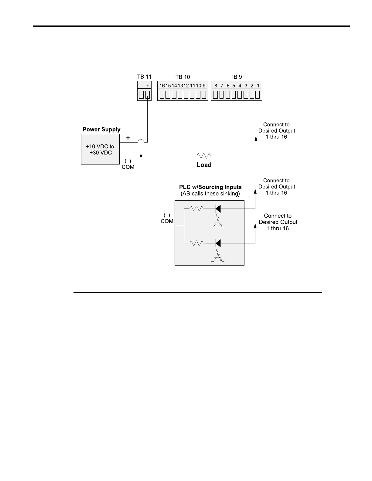
Transistor Outputs PS-6144-24-X16-M09 models include 16 transistor outputs to drive the electronic input
circuits of other control devices. The outputs are limited to 30 VDC, 50 mA each and
should not be used to control inductive devices such as solenoids, solenoid valves or
relays.
The control can be ordered with either sinking or sourcing transistor outputs. Both types
require a 10-30 VDC power supply connected to TB 11 to drive the transistor output
circuitry. The transistor output fuse will blow if the power supply polarity is incorrect, but
the circuitry will not be damaged. See Figs. 17 & 18 for fuse and transistor chip replacement.
Sinking transistor outputs (N16 controls, Figure 10) conduct to the negative terminal of TB 11. Therefore the common for TB 11 and the load must be electrically the
same. This may require connecting commons together if the power supplied to TB 11 is
not also the load power supply. Electronic counters/ratemeters often fall into this category. The power supply that powers the load does not have to be the same voltage as
the transistor power supplied to TB 11.
Sourcing transistor outputs (P16 controls, Figure 11) conduct to the positive power
terminal of TB 11. The load is therefore powered from the same supply that is providing
the transistor power.
2-8 Installation & Wiring
Page 17
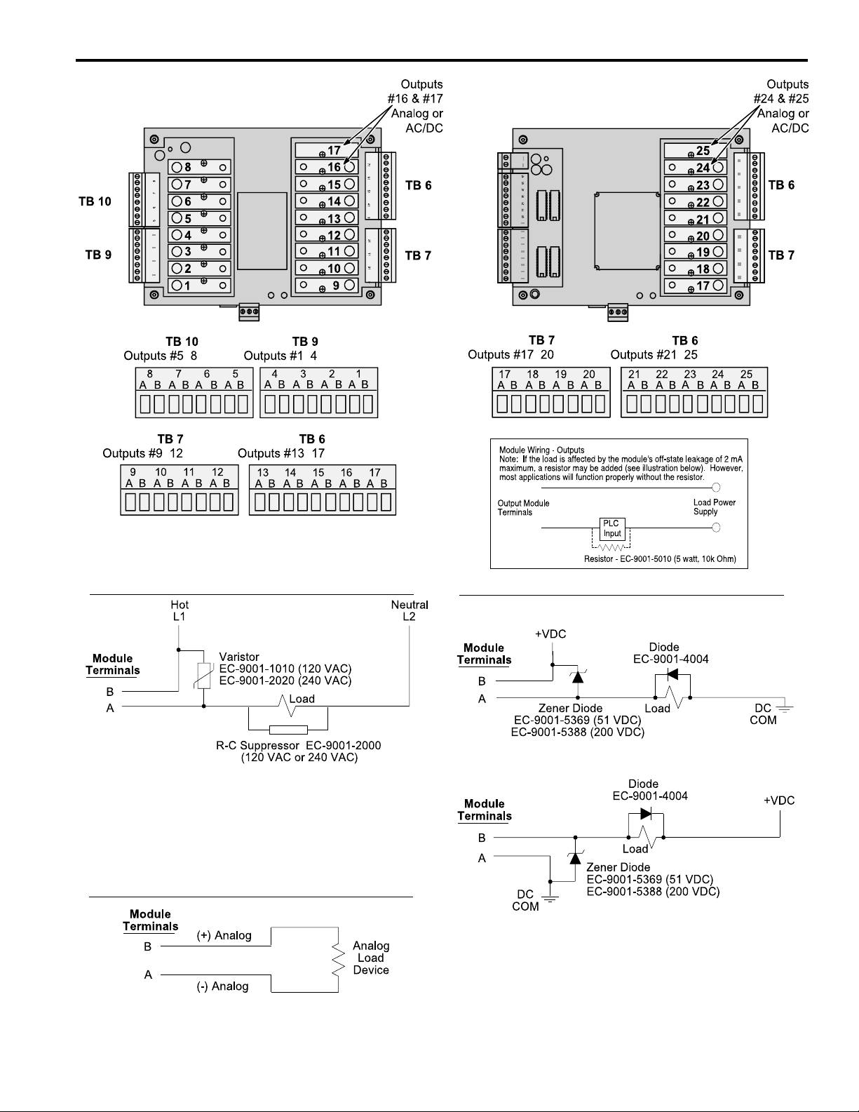
Output Wiring (cont’ d)
Figure 9—Wiring for Output Modules
PS-6144-24M17
-
-
PS-6144-24-X16-M09
-
-
--
-
-
Electro Cam
AC Output
Most applications will not need the varistor or R-C suppressor shown
above. However, when other switching devices are in series or parallel
with the AC module, voltage spikes may damage the module. Use one of
the following two methods to suppress voltage spikes.
• For infrequent switching, connect a varistor (MOV) across the terminals.
• For continuous switching, wire an R-C suppressor in parallel with the
load.
Analog Output
• Analog output modules source the analog signal.
• No external supply is required.
• Analog output signals are isolated.
DC Output
Sourcing
Sinking
Most applications will not need the diodes shown above. However, highly
inductive DC loads may damage modules by generating voltage spikes
when switched off. Suppress these voltage spikes using one of these two
methods:
• Connect a Zener diode across the terminals. This will not significantly
increase the load turn off time. Voltage rating of the diode must be
greater than the normal circuit voltage.
• Connect a reverse-biased diode across the load. This may increase the
load turn off time.
2-9 Installation & Wiring
Page 18

Output Wiring (cont’ d)
Figure 10—Wiring for Sinking Transistor Outputs (See Figure 6 for Terminal Block Locations)
Model PS-6144-24-N16-M09
-
-
Please Note:
• Outputs are rated at 30 VDC, 50 mA.
• Transistor outputs should not be used to switch inductive devices such as solenoids or
relays.
• Sinking outputs conduct to the negative terminal of TB 11 when “on.”
• The power supply shown in “Load with Built-In Power Supply” does not have to be the same
voltage as the power supply connected to TB 11.
2-10 Installation & Wiring
-
Page 19
Output Wiring (cont’ d)
Figure 11—Wiring for Sourcing Transistor Outputs (See Figure 6 for Terminal Block Locations)
Model PS-6144-24-P16-M09
-
-
-
Please Note:
• Outputs are rated at 30 VDC, 50 mA.
• Transistor outputs should not be used to switch inductive devices such as solenoids or
relays.
• Sourcing outputs conduct to the positive terminal of TB 11 when “on.”
Sinking/Sourcing Defined
Sinking means that when the logic is true and the output (or input device) is ON, the output (or input device)
is providing a DC common or ground to the connected device.
Sourcing means that when the logic is true and the output (or input device) is ON, the output (or input device)
is providing a +DC voltage to the connected device.
This information is important when interfacing an Electro Cam Corp. product with another electronic device. If you are using an Electro Cam Corp. product
input to an Allen-Bradley 1746-IN16 “sinking” input card* or similar A-B device, you have to supply a +DC voltage (Electro Cam Corp.
to this card, NOT a DC common or ground. In these cases,
*Other manufacturers include, but not limited to: Koyo (formerly GE Series 1, Texas Instruments, or Siemens SIMATIC PLS’s) that use descriptions
similar to Allen-Bradley.
Sinking
is what the card does with the input voltage; sinks it to common or ground.
Sourcing
output)
2-11 Installation & Wiring
Page 20
Keypad Wiring
Number of Keypads One or two keypads may be connected to a PS-6144 controller as shown in Figure 12.
See Figure 14 for possible system configurations.
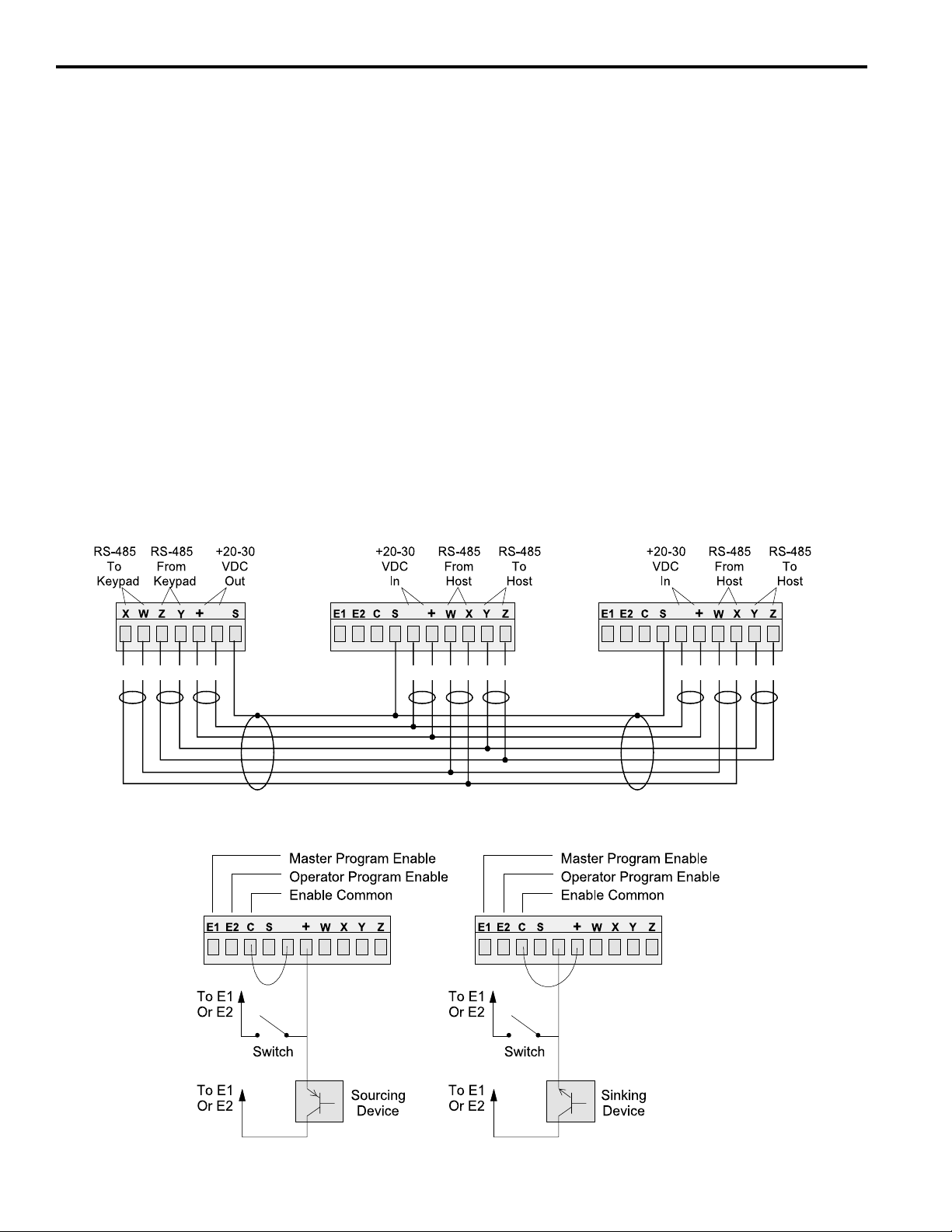
Programming Enable The wiring connector on the back of each keypad includes terminals to select Operator
or Master level programming for that keypad. These terminals can be temporarily
jumpered during set-up to allow entry of programming access codes, or they can be
switched with a variety of devices including mechanical switches, relay contacts, and
PLC DC outputs. See ENABLE CODES in the programming section for details on programming access.
If a solid state device will be activating the Programming Enable terminals, that device
will determine whether sourcing or sinking wiring should be used. For mechanical devices such as jumpers or key switches, either sourcing or sinking wiring may be used.
Figure 12—Keypad Wiring
Keypad Connector
on Controller
-
Wh Bk Gn
Bk
Rd Bk
Programming Enable, Sourcing
Keypad
Terminal Block
Keypad
Terminal Block
--
Bk Wh Bk Gn
Rd Bk
Programming Enable, Sinking
-
-
Bk
Wh Bk
Rd Bk
Gn
2-12 Installation & Wiring
Page 21
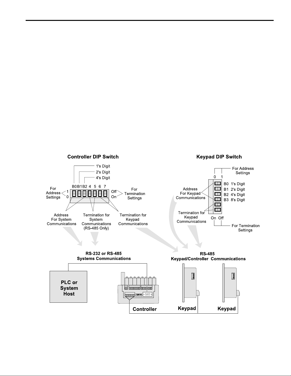
DIP Switch Configurations
DIP Switches Each keypad and controller has a DIP switch as shown in Figure 13. For convenience,
set the DIP switches correctly before mounting the units in a panel.
Keypad Settings The address and termination settings on the keypad DIP switch apply to the RS-485
network that connects it to the controller. See Figure 14 for guidelines and sample
settings.
Controller Settings The address settings on the controller DIP switch apply to a network connecting the
controller to a PLC or other system host. When the DIP switch is set to zero, the default
address programmed through the COMMUNICATIONS function takes affect. Whereas
the DIP switches can set a maximum address of “7”, the COMMUNICATIONS function
can establish much higher address numbers. These settings are not related to com-
munications with the keypads.
Two sets of termination switches are included on the controller. One set establishes the
termination value for an RS-485 network connecting the controller to a PLC or other
system host. It does not apply to an RS-232 network. The other termination switches
apply to the keypad network. See Figure 14 for guidelines and sample settings.
Figure 13—DIP Switches and Related Communications Networks
NOTE: Both termination switches in a pair must be in the same position.
2-13 Installation & Wiring
Page 22
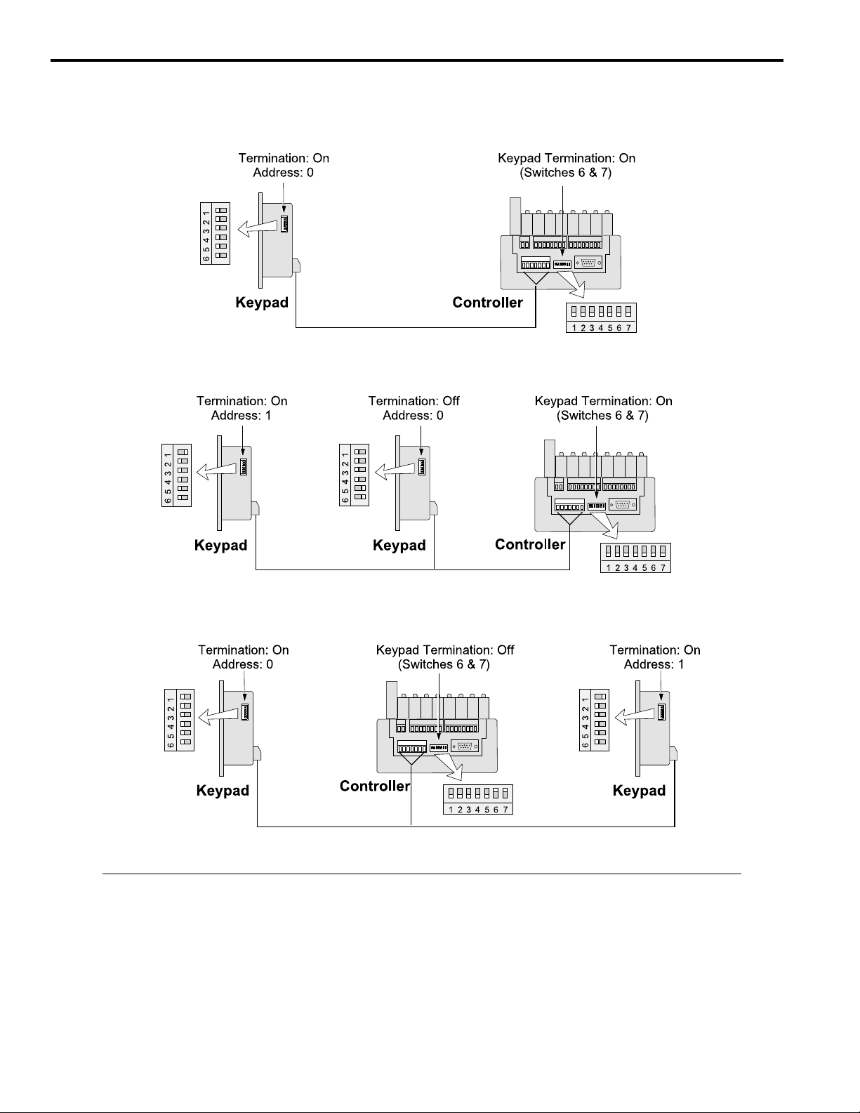
DIP Switch Configurations (cont’d)
Figure 14—DIP Switch Settings for Typical Systems
One Keypad
Two Keypads, Controller on End
Two Keypads, Controller in Middle
DIP Switch Guidelines
Termination: • Termination must be “on” for devices on each end of the chain.
• Termination must be “off” for devices in the middle of the chain.
• Both termination switches in a pair must be in the same position.
Address: • Keypad addresses must be assigned starting with “0” and increasing sequentially.
• The physical location of a keypad in the chain has no relationship to its address.
• During initial programming, the KEYBOARD QTY function must be used to enter the
number of keypads in the chain. KEYBOARD QTY can be accessed only through the
keypad whose address is “0.”
2-14 Installation & Wiring
Page 23
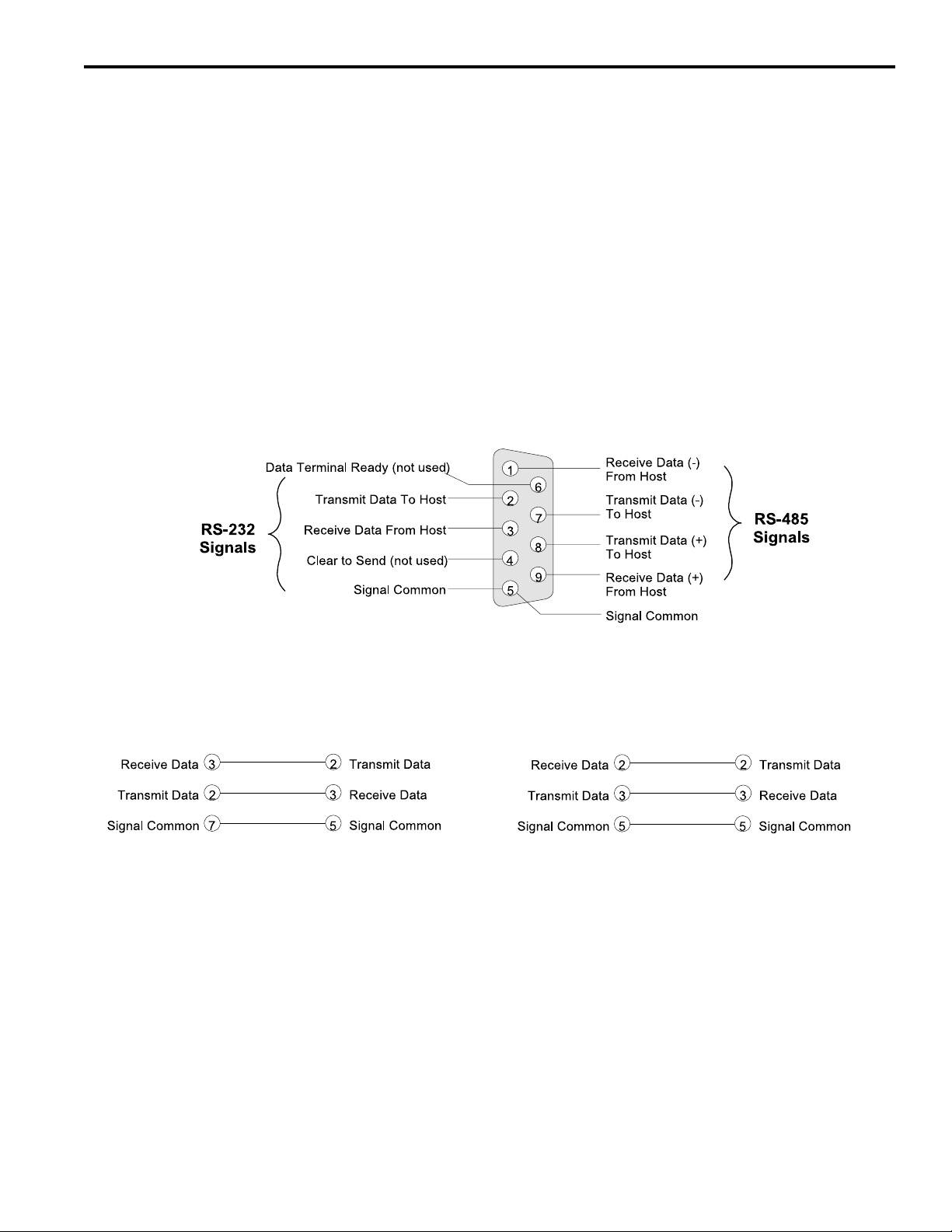
Communications Wiring
DB-9F Port Serial communication to a PLC or other system host is provided through a DB-9 female
connector as shown in Figures 5 & 6. This connector can be wired for RS-232 or RS485 communications.
RS-485 RS-485 can be used for “multi-drop” networks where more than one controller could be
connected to the system host.
RS-232 RS-232 can connect only a single PS-6144 to a system host.
RS-232/485 Selection Use the COMMUNICATIONS function to select RS-232 or RS-485 communications.
Figure 15—Communications Wiring
DB-9 Female Connector on Controller
(See Figures 5 & 6 for Location)
RS-232 Cable Wiring
DB-25 (Host) to DB-9F (PS-6144)*
*Pins 1, 4, 6, 7 and 8 must NOT be connected.
Damage may result from using an off-the-shelf
RS-232 communications cable.
Be sure to follow illustrations, as they are NOT
STANDARD configurations!
RS-232 Cable Wiring
DB-9 (Host) to DB-9F (PS-6144)*
2-15 Installation & Wiring
Page 24

Resolver Installation
General Information Choose a mounting location for the resolver that allows convenient mechanical con-
nection of the resolver shaft to the machine. The resolver is normally driven at a 1:1
ratio to machine cycles, but this is not true in all applications. The shaft can be coupled
to the machine using a chain and sprocket, timing pulley and belt, or a direct shaft-toshaft coupling. If a shaft-to-shaft coupling is used, Electro Cam Corp. recommends the
use of a FLEXIBLE coupling. Flexible couplings are available through Electro Cam
Corp. and are included on the price list.
Turn power to the machine OFF prior to installation!
No provision need be made for physically rotating the resolver shaft with respect to the
machine shaft. The PS-6144 can be easily programmed to set any resolver position as
the 0° position.
If possible, select a location that shelters the resolver from accidental mechanical abuse,
lubricants, washdown chemicals or any other liquids. Most Electro Cam resolvers have
a NEMA 4 rating or better, but avoiding contaminants will maximize their reliability and
service life.
Figure 16 shows three commonly used Electro Cam resolvers.
Ambient Temperature Electro Cam resolvers have an ambient temperature range of -40° to +125°C (-40° to
+257°F).
Resolver Wiring Cables for non-stainless Electro Cam resolvers are shipped with one end soldered to
the resolver connector. The connector for the other end is mounted on the controller.
The shield is connected at both ends of the cable to prevent damage due to electro-
static discharge. If electrical noise problems are suspected when the control is in operation, call Electro Cam Corp. for advice regarding shielding.
The resolver cable used with the stainless steel resolvers (PS-5300-02-XXX) does not
have a connector at the resolver end because screw terminals are used inside that
resolver. When properly connected, both ends of the cable shield will be connected. If
electrical noise problems are suspected when the control is in operation, call Electro
Cam Corp. for advice regarding shielding.
Resolver cables supplied by Electro Cam are a special type consisting of three individually twisted/shielded pairs with a common braid shield. This insures that reliable
position information is being received by the controller. The use of other cable types
could degrade the accuracy of the position signals and make them more susceptible to
electrical noise. For these reasons, it is recommended that customers do not make
their own resolver cables. Electro Cam will make resolver cables any length up to 1000'
and can expedite shipment as required.
2-16 Installation & Wiring
Page 25
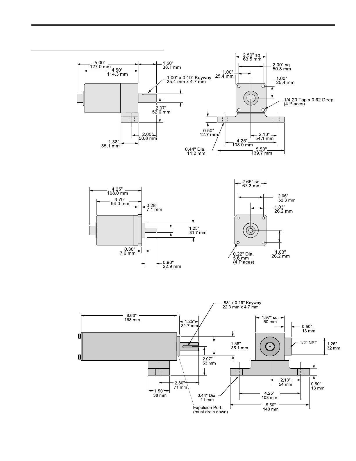
Resolver Dimensions
Figure 16 - Electro Cam Corp. Resolvers
Foot Mount
With Rear Connector (shown):
PS-5275-11-ADR
With Side Connector:
PS-5275-11-ADS
Cable:
PS-5300-01-XXX where “XXX” is length in feet.
0.749/
0.747"
19.02/
18.97 mm
Flange Mount
With Rear Connector (shown):
PS-5238-11-ADR
With Side Connector:
PS-5238-11-ADS
Cable:
PS-5300-01-XXX where “XXX” is length in feet.
Stainless Steel
0.375/
0.374"
9.53/
9.50 mm
.625/
.624" dia.
15.88/
15.85 mm
Horizontal Mount
(shown) PS-5262-11-CTG (with right connector)
PS-5262-11-CTL (with left connector)
Vertical Mount (Shaft Up)
PS-5262-11-CTG-V (with right connector)
PS-5262-11-CTL-V (with left connector)
Cable: PS-5300-02-XXX where “XXX” is length in feet.
For horizontal applications
2-17 Installation & Wiring
Page 26
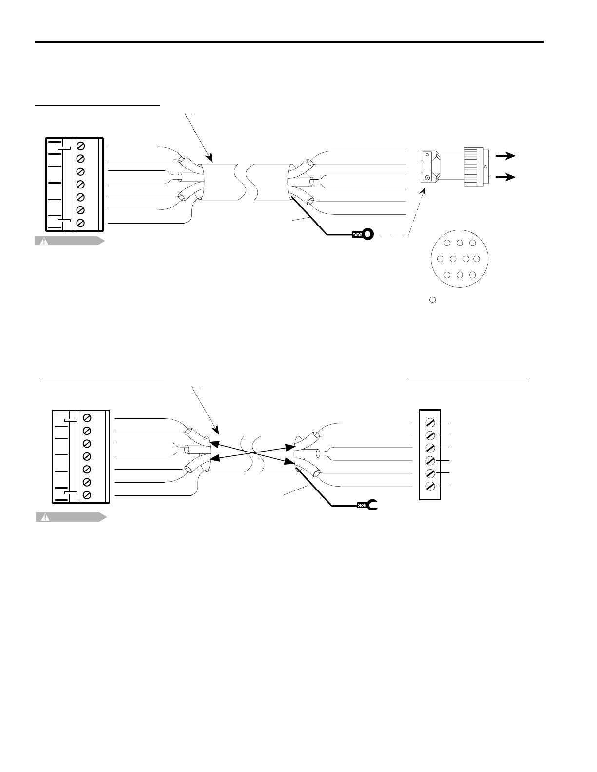
Resolver Cables
Cable for Resolver with Cannon Connector
PT# PS-5300-01-XXX (XXX = Length in Feet)
Connector - Controller End
PT# PS-5300-01-TER
(Weidmuller # BLA7 12822.6)
Green
GR
Black
BK
Red
RD
Black
BK
White
WT
Black
BK
Shield
SH
CAUTION
Shielding Note: Resolver cables made after 3-2-93 have a ring lug on a black shield wire at
the resolver end. The ring lug should be attached to one of the resolver connector strain relief
screws to protect against static discharge through the resolver cable. In some installations,
it may be advisable to disconnect the ring lug to prevent ground loops through the cable shield.
Consult Electro Cam if electrical noise problems are suspected.
Cable Type:
3 individually shielded pairs, 22 gauge
Pin B - Green
Pin A - Black
Pin D - Red
Pin C - Black
Pin F - White
Pin E - Black
Shield
(see note below)
Shield
Front View
(pin out)
A
B
C
J
XX
E
D
= Not Used
X
H
X
G
K
X
F
Cable for Stainless Steel Resolver with Terminal Strip Connections
Connector - Controller End
PT# PS-5300-01-TER
(Weidmuller # BLA7 12822.6)
GR
BK
RD
BK
WT
BK
SH
CAUTION
Green
Black
Red
Black
White
Black
Shield
PT# PS-5300-02-XXX (XXX = Length in Feet)
Cable Type:
3 individually shielded pairs, 22 guage
White
Black
Black
Red
Black
Green
Shield
Shield
(see note below)
Shielding Note: This type of resolver cable will have a spade lug connected to the shield at the resolver end. The lug should
be attached to the grounding stud on the cover plate of the resolver. In some installations, it may be advisable to disconnect
the lug to prevent ground loops through the cable shield. Consult Electro Cam if electrical noise problems are suspected.
Connector Inside Resolver
(cable is stripped and tinned at
both ends)
WHITE
BLK (P/W) WHITE
BLK (P/W) RED
RED
BLK (P/W) GREEN
GREEN
2-18 Installation & Wiring
Page 27
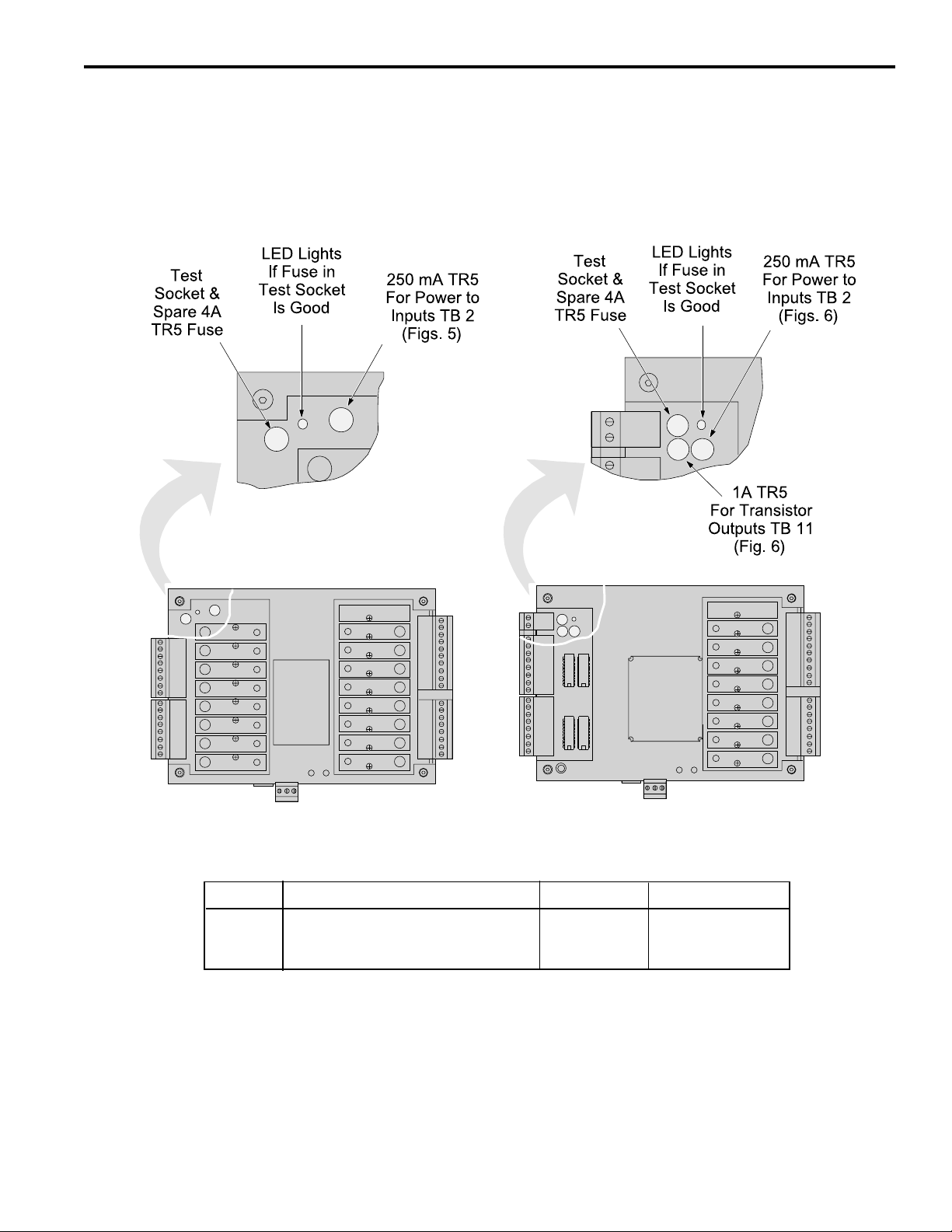
Fuse Tester & Fuse Replacement
Fuse Tester Figure 17 shows the location of a fuse test socket and LED which can be used to test
TR5 style fuses. PS-6144 controllers are shipped with a spare 4A fuse mounted in the
test socket.
Figure 17—TR5 Fuse Tester and Fuse Locations
PS-6144-24M17
Replacement TR5 Fuse Part Numbers
Rating Function ECC Part # Wickmann Part #
250 mA Power for Inputs (TB 2) PS-9005-0250 19374-035
1 A Power for Transistor Outputs (TB 11) PS-9005-0001 19370-048
4 A Fuse for Output Modules PS-9005-0004 19370-062
PS-6144-24-X16-M09
2-19 Installation & Wiring
Page 28
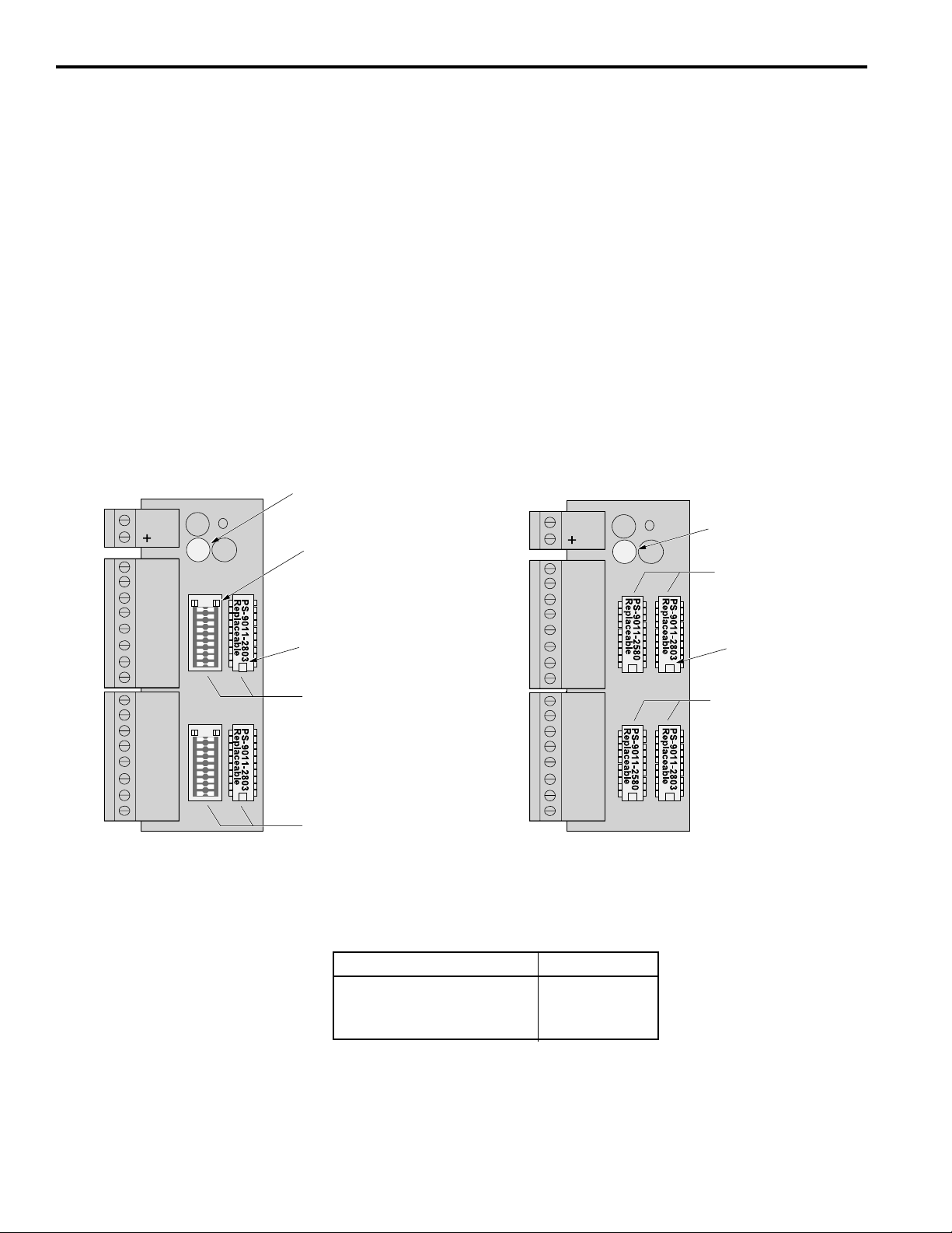
Output T ransistor Replacement
Check Fuse First If all of the transistor outputs fail to work, check the 1A fuse shown in Figures 17 & 18.
Also check to be sure that a 10–30 VDC power supply is connected to TB 11, Figure 6.
Correct Problems Chips will most likely be damaged by one of two events:
• A short circuit connected to one of the transistor outputs.
• A load exceeding 50 mA connected to one of the transistor outputs.
Before replacing a transistor output chip, fix the problem that damaged it.
Proper Placement When replacing a chip, be sure that all of the pins are properly seated in the socket.
Position the notch on the end of the chip as shown below.
Figure 18—Transistor Chip Replacement
TB 11
TB 10
TB 9
PS-6144-24-N16-M09
Sinking Outputs
-
16 15 14 13 12 11 10 9
8 7 6 5 4 3 2 1
1A Fuse for
Transistor Outputs—
If blown, no transistor
outputs will work.
See Figure 17
for testing.
Empty
Socket Holes (2)
Position Notches
Like This
Jumper Block & Chip
For Outputs 9–16
• Jumper block
does not normally
need replacement.
Jumper Block & Chip
For Outputs 1–8
• Jumper block
does not normally
need replacement.
TB 11
TB 10
TB 9
PS-6144-24-P16-M09
Sourcing Outputs
-
16 15 14 13 12 11 10 9
8 7 6 5 4 3 2 1
1A Fuse for
Transistor Outputs—
If blown, no transistor
outputs will work.
See Figure 17
for testing.
Chips for
Outputs 9–16
• Replace PS-9011-2580 first.
• Replace PS-9011-2803 if
that doesn’t work.
Position Notches
Like This
Chips for
Outputs 1–8
• Replace PS-9011-2580 first.
• Replace PS-9011-2803 if
that doesn’t work.
2-20 Installation & Wiring
Replacement Part Numbers
Description ECC Part #
Replacement Chip-Sourcing PS-9011-2580
Replacement Chip-Sinking PS-9011-2803
DIP Jumper Block PS-9006-0015
Page 29
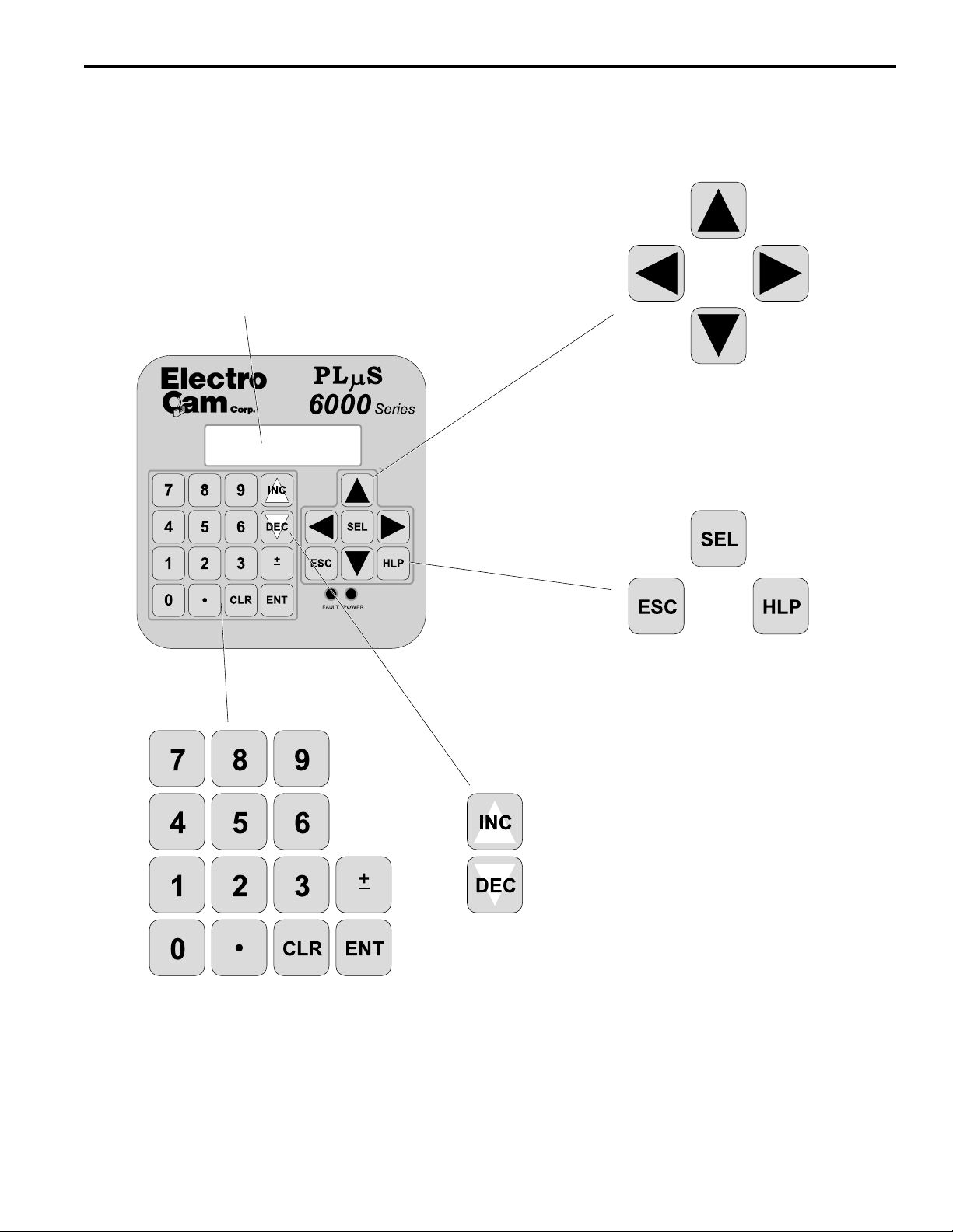
Keypad Overview
Figure 19—Keypad Keys and Corresponding Functions
Main Screen
• Shows Active Program, RPM, Position, and
Group # if applicable.
• See MAIN SCREEN in this Section for details.
• Press SEL key when cursor is on “MENU” to enter
Menu Tree (Fig. 20) and initiate programming.
PGM:1 RPM:1500
MENU< POS: 180
Cursor Keys
• Scroll through Menu Tree (Fig. 20).
• Move around within a screen.
• Scroll through setpoints.
ESC, SEL, HLP Keys
• ESC exits from current menu level to pre-
vious menu, or aborts numeric entry.
• SEL enters a new menu level; toggles a
value; and selects an output group if
multiple groups with different offsets are
used.
• HLP shows help regarding menu selection and what keys to press. Use this key
if unsure what to do.
INC, DEC Keys
• Increment or decrement a value within a field.
Numeric Keys
• Input numeric values within a field.
• ENT must be pressed to enter the value; entry will flash until ENT is pressed.
• CLR will backspace within an entry prior to pressing ENT.
• ± will convert a positive number to a negative number, or vice versa.
• Hold for rapid scrolling of value.
3-1 Programming
Page 30
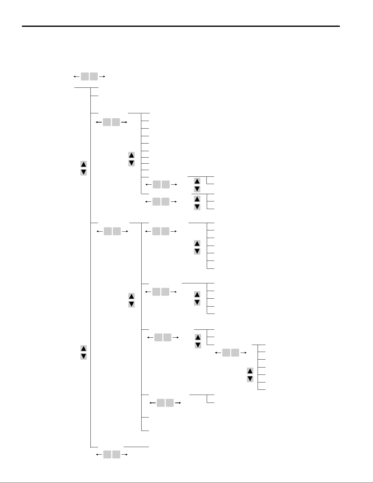
Menu T ree
Figure 20—PS-6144 Menu Tree
• Functions are listed alphabetically in Section 3 of this manual starting on page 3-4.
ESC SEL
MAIN SCREEN
PASSWORD
SETPOINTS
SETUP MENU
ESC SEL
DEFAULT PROGRAM
SPEED COMP
TIMED OUTPUTS
OFFSET
MOTION DETECTION
ANALOG OUTPUT
PULSE COPY
CHN COPY
PGM COPY
I/O STATUS MENU
ESC SEL
SYSTEM INFO MENU SETPOINT USE
ESC SEL
CONFIG MENU HARDWARE MENU
ESC SEL
ESC SEL
INPUT STATUS
OUTPUT STATUS
SOFTWARE VERSION
MODEL & OPTIONS
KEYBOARD QTY
INCREASING DIR
SCALE FACTOR
SHAFT POSITION
ANALOG QTY
RESOLVER TYPE
PGM SEL MODE
DISPLAY MENU RATE SETUP
ESC SEL
PGM ENABLE MENU ENABLE CODES
ESC SEL
CHN ANDING MENU
ESC SEL
OUTPUT GROUPS
COMMUNICATIONS MENU
TEST MENU MEMORY TESTS
ESC SEL
TOGGLE RPM
RPM UPD RATE
SPD COMP MODE
GRP POS DISP
PER CHN ENABLE
ENABLE OPTIONS SETPOINTS
ESC SEL
DEFAULT PROGRAM
SPEED COMP
TIMED OUTPUTS
OFFSET
MOTION DETECT
MOTION ANDING
ANALOG OUTPUTS
OUTP ENAB AND
3-2 Programming
Page 31

Initial Programming
Bench Test To test the PS-6144 prior to installing it, do the following:
1. Plug output modules into the controller beginning with Position 1 on the PS-614424M17, or Position 17 on the 6144-25. See Figure 9.
2. Connect a resolver. See Figure 16.
3. Connect the keypad/display to the controller. See Figure 12.
4. Set the keypad DIP switch to address “0” and termination “on,” as shown in Figure
13. Set switches 6 and 7 on the controller DIP switch to “on,” also shown in Figure
13.
5. Use two jumper wires to enable Master Level programming as shown in Figure 12.
Connect one jumper from “+” of the keypad terminal block to “C.” Connect the other
jumper from “–” to “E1.” These jumpers will permit access to the entire menu tree
shown in Figure 20.
6. Connect DC input power.
When experimenting with the controller, note that the LED on an output module will
light when that output channel is turned on. By hand-turning the resolver shaft and
watching the module LED’s, you can observe the effects of programming setpoint values. Remember that on a PS-6144-24-X16-M09, outputs 1-16 are transistor outputs.
To activate the LED on a module installed in Position 17, enter the setpoint values into
Output Channel 17.
Machine Setup Before installing the PS-6144 on a machine, be sure the DIP switches are properly set
as shown in Figures 13 & 14. After installing the unit, program the following set-up
information into the controller before attempting any other programming:
Information Menu Selection Page
Direction of Rotation INCREASING DIR 3-11
Scale Factor SCALE FACTOR 3-25
Shaft Position SHAFT POSITION 3-28
No. of Keypads KEYBOARD QTY 3-12
No. of Analog Outputs ANALOG QTY 3-5
No. of Output Groups OUTPUT GROUPS 3-18
Modes for Output Groups OUTPUT GROUPS 3-18
Group Display Mode GRP POS DISP 3-10
Group Offsets OFFSET 3-16
Once this information is entered, setpoints can be established and modified in the groups
and output channels desired. Refer to Section 5 for information on using groups and
modes.
3-3 Programming
Page 32

Analog Output
r
Menu Path MAIN SCREEN to SETUP MENU to ANALOG OUTPUT
Purpose Analog output signals are linearly proportional to the resolver RPM. Two types of ana-
log output modules are available: 0-10 VDC and 4-20 mA.
This function assigns Offset and High RPM values to output positions for analog mod-
ules.
Screen
ANALOG MODULE: 1<
OF: 20 HI: 1500
Analog Module Numbe
Analog High RPM
Analog Offset
Module Number The following table shows the relationship between the analog module number on the
screen and the module position on the controller back. See Figure 9 for an illustration of
analog module positions.
Module #1 Module #2
Model On Screen On Screen
PS-6144-17 Output #17 Output #16
PS-6144-25 Output #25 Output #24
• Analog characteristics can be programmed for Modules #1 and #2 even if no analog
modules are physically mounted on the controller. Programming can be done first,
and modules mounted later.
• To program Offset and High RPM for Module #2, be sure the ANALOG QTY function
(next page) is set to “2.” If ANALOG QTY is set to “1,” programming for Module #2 will
not be available.
• When two analog outputs are used, the two outputs can have different values for
Offset and High RPM.
To program Module Number, move the cursor to “Module” and use the numeric keys
and ENT.
High RPM Analog High RPM is the resolver speed at which full scale analog output will occur. It is
programmed in whole RPM. When this speed is reached, the analog output signal level
will be at full scale (10 VDC or 20 mA). Increasing speed beyond the High RPM will not
increase the analog output beyond full scale.
To program High RPM, move the cursor to “Hi” and use the numeric keys and ENT.
3-4 Programming
Page 33

Analog Output (Cont’d)
s
Offset Analog Offset is the analog signal level that will be output when the resolver is at zero
RPM. This allows the minimum analog signal to be greater than zero volts or 4 mA.
Because the analog output module has 4096 increments (12 bits) of signal level available, the offset is specified as the number of increments of signal that should be output
at zero RPM. Calculate Analog Offset values as follows:
For 0-10 VDC: (Minimum Signal/10) x 4096
Example: For a 2 VDC minimum signal; Offset = (2/10) x 4096 = 819
For 4-20 mA: ((Minimum Signal - 4)/16) x 4096
Example: For a 5 mA minimum signal; Offset = ((5-4)/16) x 4096 = 256
To program Analog Offset, move the cursor to “Of” and use the numeric keys and
ENT.
See Also OUTPUT STATUS
Analog Quantity
Menu Path MAIN SCREEN to CONFIG MENU HARDWARE MENU
to ANALOG QTY
Screen
Purpose This screen displays the number of analog outputs that will be programmed into the
controller.
The controller can have zero, one or two analog outputs, and each can be offset and
scaled by different values. See ANALOG OUTPUT for details.
Programming Use the numeric keys to enter “0,” “1,” or “2” analog channels. An analog output module
is required to generate an analog output signal.
See Also ANALOG OUTPUT
OUTPUT STATUS
ANALOG
QTY: 1<
Number of Analog Output
3-5 Programming
Page 34

b
Channel Copy
s
Menu Path MAIN SCREEN to SETUP MENU to CHN COPY
Purpose Channel Copy allows you to copy all setpoints to another channel in the specified pro-
gram.
Screens The Channel Copy function consists of four screens:
SOURCE PGM:---<
DEST PGM:---<
SOURCE CHN:---<
DST CHN:---<
DEST CHN:
EXECUTE<
Programming Use the numeric keys and SEL to enter program numbers.
During programming, the cursor keys allow you to move between the Source and Destination screens to allow you to change values before selecting EXECUTE.
Program containing channels
Program containing channel
to be copied
Channel to be copied
Destination channel to be copied to
Move cursor to EXECUTE, then pres
SEL to copy program
Communications
Menu Path MAIN SCREEN to CONFIG MENU
to COMMUNICATIONS
Purpose This function sets the communications type, controller address, and baud rate for
communicating with a host computer.
Communications Type: RS-232 or RS-485
Screen
TYPE:485 ADR: 1<
BAUD: 9600
Type Use SEL to toggle between RS-232 and RS-485 communications on units shipped with
date code 9549 or newer (default setting is RS 485).
Address The address must be unique for each controller installed on a network. This address is
used by a host computer to identify and send information to a particular controller. A
PLuS controller will ignore incoming information if the address field of the communication packet does not match the address of the controller.
The address set through COMMUNICATIONS programming takes effect only when the
DIP switch shown in Figure 13 is set to an address value of zero. Whereas the DIP
switch can set a maximum address of “7,” the COMMUNICATIONS function can set
addresses ranging from 0-255.
Use the numeric keys and ENT to program the address.
Address: 0-255
Baud Rate: 4800, 9600, 19.2Kb, 38.4K
3-6 Programming
Page 35

Communications (Cont’d)
h
Baud Rate Use SEL to toggle between the available baud rates. The baud rate must match that of
the host computer. Available baud rates are:
4,800; 9,600; 19,200; and 38,400.
Note: Effective with Software Versions 1.97 and higher, the communications
screen has been revised as shown below:
TYPE: 232 ADR:1<
TRM: ON BR: 9600
Termnination Setting
The termination setting should be ON if TYPE is set to RS-232, or if TYPE is set to RS485 and only one PS-6144 controller is in the multi-drop network. Setting the termina-
tion to OFF in these configurations may cause inaccurate RPM readings.
If multiple PS-6144 controllers are connected in an RS-485 network, termination should
be set to OFF on one and only one PS-6144 controller.
The termination setting in this screen is independent of all DIP switch settings. Use the
SOFTWARE VERSION function to determine version number.
Default Program
Menu Path MAIN SCREEN to SETUP MENU DEFAULT PROGRAM
Background The PS-6144 controller can store up to 48 programs in its memory. The Default Pro-
gram is the program that controls the output channels when terminals 1–8 of TB 3,
Figure 7, are “off.”
The Active Program is the program number that is currently controlling the output
channels. If there are program select inputs on TB 3, those inputs will determine the
Active Program, and the Default Program will be ignored. If no hardware inputs are
“on,” the Default Program will become the Active Program.
For installations where the program select inputs on TB 3 are not used, the Default
Program will always be the Active Program.
This function displays the current Default Program and allows you to select a different
one.
Screen
Programming Use the numeric keys and ENT to enter or modify the Default Program.
DEFAULT PGM: 0
ACTIVE PGM: 0
Injury and property damage hazard may occur due to changes in machinery operation. Program the Default Program with settings that will eliminate this hazard in the event of sudden activation.
Enter new Default Program throug
Numeric Keypad, then press ENT.
See Also PGM SEL MODE
3-7 Programming
Page 36

Enable Codes
r
Menu Path MAIN SCREEN to CONFIG MENU
to PGM ENABLE MENU ENABLE CODES
Background The PS-6144 has three levels of programming access: Operator, Setup, and Master in
order of increasing capabilities. Figure 21 lists the menu functions that can be programmed under the various levels of access.
Programming levels can be activated, or “enabled,” by entering a password on the
keypad, or by activating Terminals E1 or E2 on the back of the keypad as shown in
Figure 12. The first two rows of Figure 21 show which methods can be used to enable
the various levels of programming access.
Screen
Operation • Each programming level can have only one code. That code is stored in the controller
See Also PER CHN ENABLE
LEVEL: OPERATOR
PASSWORD: 1234
This screen is used to establish the numbers that will be used as passwords to enable
the Operator, Setup, and Master levels.
Use the SEL key to toggle between enable levels.
Use the numeric keys, followed by ENT to assign codes.
and applies to all keypads connected to that controller.
• If a code is entered into a keypad that has a programming enable terminal energized,
the access level will be the highest of the two.
• If one keypad in a two-keypad system is enabled, the other keypad will continue to
operate in the “Normal Display” mode.
• If both keypads in a two-keypad system are enabled, each keypad will operate at the
programming level enabled on it. For example, if Operator Level is enabled on Keypad 1, and Setup Level is enabled on Keypad 2, Keypad 1 will operate at the Operator Level and Keypad 2 will operate at the Setup Level.
ENABLE OPTIONS
PASSWORD
Enable Level: Operator, Setup, or Maste
Password Number
3-8 Programming
Page 37

Enable Codes (cont’d)
Figure 21—Programming Access
Levels for Various Menu Items
Can Be Enabled By…
Keypad Terminal --- Yes (E2) No Yes (E1)
Password --- Yes Yes Yes
Menu Item Access
Password Enter Enter Enter Program
Setpoints View Program
Setup Menu
Default Program View Program
Timed Outputs View Program
Speed Comp View Program
Offset View Program
Motion Detect View Program
Analog Output View Program
Pulse Copy View --- Program Program
CHN Copy View --- Program Program
PGM Copy View --- Program Program
I/O Status Menu
Input Status View View View View
Output Status View View View View
System Info Menu
Setpoint Use View View View View
Software Version View View View View
Model & Options View View View View
Config Menu
Hardware Menu
Keyboard Qty --- --- --- Program
Increasing Dir --- --- --- Program
Scale Factor --- --- --- Program
Shaft Position --- --- --- Program
Analog Qty --- --- --- Program
Resolver Type --- --- --- Program
Pgm Sel Mode --- --- --- Program
Display Menu
Rate Setup --- --- --- Program
Toggle RPM --- --- --- Program
RPM Update --- --- --- Program
Spd Comp Mode --- --- --- Program
Grp Pos Disp --- --- --- Program
Pgm Enable Menu
Enable Codes --- --- --- Program
Per Chn Enable --- --- --- Program
Enable Options
Setpoints --- --- --- Program
Default Program --- --- --- Program
Speed Comp --- --- --- Program
Timed Outputs --- --- --- Program
Offsets --- --- --- Program
Motion Detect --- --- --- Program
Analog Output --- --- --- Program
Chn ANDing Menu
Motion ANDing --- --- --- Program
Outp Enab AND --- --- --- Program
Output Groups --- --- --- Program
Communications --- --- --- Program
Test Menu
Memory Tests --- --- --- Run
1
Can be programmed only if specified through PER CHN ENABLE and ENABLE OPTIONS.
2
KEYBOARD QTY can be programmed only through the keypad whose address is “0.” See Figure 14.
Programming Level
Normal
Display Operator Setup Master
1
Program Program
1
Program Program
1
Program Program
1
Program Program
1
Program Program
1
Program Program
1
Program Program
3-9 Programming
2
Page 38

Enable Options
t
Menu Path MAIN SCREEN to CONFIG MENU
to PGM ENABLE MENU to ENABLE OPTIONS
Purpose The Enable Options screen controls Operator Level access to SETUP MENU program-
ming as indicated in Figure 21, note 1.
Screen
SETPOINTS<
ENABLE: ON
SETPOINTS or SETUP MENU screen.
Scroll through choices with UP and Down cursor keys.
OPERATOR ENABLE: ON/OFF
(Toggle with SEL key)
This screen lists the various items in the SETUP MENU, and allows you to turn Operator access to those items on or off.
Access to the “on” items will be available only for those output channels that
have been turned ON in PER CHN ENABLE.
Programming Press the Up Cursor and Down Cursor keys to select the function you wish to change.
Press the SEL key to turn Operator access ON or OFF.
Setup Menu Items Access can be turned on or off for the following SETUP MENU items:
SETPOINTS, DEFAULT PROGRAM
SPEED COMP
OFFSET
MOTION DETECT
ANALOG OUTPUTS
See Also PER CHN ENABLE
Group Position Display
Menu Path MAIN SCREEN to CONFIG MENU DISPLAY MENU
to GRP POS DISP
Purpose The Group Position Display determines whether each output group can have its own
position in the machine cycle, or if all groups share one position. Because the position
of a group operating in Mode 1 or 2 changes each time the group’s input terminal is
energized, GRP POS DISP must be set to EACH if any groups are assigned to
Mode 1 or Mode 2.
Screen
GROUP POSITION
DISPLAY: EACH<
Group Position Display Mode: EACH = Each oupu
group has its own offset value; ONE = One value
of offset is shared by all output groups.
3-10 Programming
Page 39

Group Position Display (Cont’d)
PGM: 1 RPM: 1500
MENU< POS: 180
Machine Speed
Machine Position = Shaft Position + Offset
To enter Menu Tree, press SEL when cursor is here
Active Program
PGM: 1 RPM: 1500
MENU< GRP1: 180
Mode 1 or 2: Position = Preset + change since last reset
Mode 0, 3, 4, 5: Position = Shaft Position + Group Offset
Group #: To change, put cursor here and press SEL
To enter Menu Tree, put cursor here and press SEL
The value selected in this screen determines the appearance of the main screen as
shown below:
Main Screen— • One Output Group, and GRP POS DISP Set to “One” or “Each”
• Multiple Output Groups, and GRP POS DISP set to “One”
Main Screen— • Multiple Output Groups and GRP POS DISP Set to “Each”
Programming Enter the GRP POS DISP function and press SEL to toggle between “ONE” and “EACH.”
• GRP POS DISP must be set to “EACH” to assign different offsets to groups through
OFFSET programming.
• If groups have been assigned different offsets through OFFSET programming, setting GRP POS DISP to “ONE” will immediately change the individual group offsets to
the value of Group 1.
See Also OFFSET
SHAFT POSITION
OUTPUT GROUPS
MAIN SCREEN
Increasing Direction
Menu Path MAIN SCREEN to CONFIG MENU HARDWARE
to INCREASING DIR
Purpose The Increasing Direction screen displays the direction of resolver rotation (CW or CCW
as viewed from the shaft end) that will cause the position display to increase in value.
Screen
INCREASING
DIR: CCW<
Direction of resolver shaft rotation (viewed from
shaft end) that will cause the postion display to
increase in value.
Changing Direction Press SEL to toggle the value of increasing direction. The new value will begin flashing.
This is normally set so the position value increases as the machine turns in its forward
direction.
Press the ENT key to confirm your selection.
3-11 Programming
Page 40

Input Status
)
Menu Path MAIN SCREEN to SETUP MENU to I/O STATUS
to INPUT STATUS
The input status screen displays the On/Off status of the DC inputs on Terminal Blocks
TB 1 and TB 3, Figure 7.
Screens
Selecting Inputs You may view inputs 1-8 or 9-16. Press SEL to toggle between the two groups of
12345678 INPUT
01001001 1-8<
Input On/Off Status (0=Off, 1=On)
90123456 INPUT
01001001 9-16<
Inputs are numbered 1 through 16, but only 8 inputs are shown at one time. The On/Off
status is shown under the input number; 0=Off, 1=On.
inputs.
Input Numbers (1-8)
Input Numbers (9-16
Keyboard Quantity
Menu Path MAIN SCREEN to CONFIG MENU HARDWARE MENU KEYBOARD
QTY
Purpose The Keyboard Quantity screen shows the number of keypads the controller will com-
municate with.
Screen
KEYBOARD
QTY: 1<
Number of keyboard/display units
attached to controller
The controller will attempt to establish communication with as many keypads as are
programmed through this screen. Keypads are assumed to be addressed sequentially,
starting at address “0” as shown in Fig. 14.
Keypad “0” You can change the number of keypads shown in KEYBOARD QTY only from the
keypad whose address is “0.”
If KEYBOARD QTY is set to “2,” but only one keypad is physically connected,
Menu Tree operation will be very slow. Change KEYBOARD QTY to “1” to restore
normal Menu Tree speed.
3-12 Programming
Page 41

Main Screen
PGM: 1 RPM: 1500
MENU<
Machine position not shown above toggle RPM
t
PGM: 1 RPM: 1500
MENU< GRP1: 180
Mode 1 or 2: Position = Preset + change since last reset
Mode 0, 3, 4, 5: Position = Shaft Position + Group Offset
Group #: To change, put cursor here and press SEL
To enter Menu Tree, put cursor here and press SEL
Two Screens On power-up, or after five minutes of keypad inactivity, the controller will display one of
two main screens:
Main Screen— • One Output Group, and GRP POS DISP Set to “One” or “Each”
• Multiple Output Groups, and GRP POS DISP set to “One”
Active Program
PGM: 1 RPM: 1500
MENU< POS: 180
To enter Menu Tree, press SEL when cursor is here
Main Screen— • Multiple Output Groups and GRP POS DISP set to “Each”
Active Program The PS-6144 can store up to 48 programs of setpoints. The “Active Program” is the
program currently controlling the output channels.
Machine Speed
Machine Position = Shaft Position + Offse
If hardware inputs are being used to select the Active Program, the display will
indicate the program selected by the inputs. If all hardware inputs are off, the Active
Program will be the Default Program specified through the DEFAULT PROGRAM function. For information on using hardware inputs to select the Active Program, see “Controller Input Wiring” in Section 2.
If hardware inputs are not used, the Active Program will be the program specified
through the DEFAULT PROGRAM function.
Machine Speed When the machine is moving, Machine Speed is displayed in user selectable units of
RPM (revolutions per minute), BPM (bags per minute), or CPM (cartons per minute).
Machine Speed is displayed as a value which is 1X, 2X, or 3X the resolver RPM. See
RATE SETUP for details.
Toggle RPM Machine or Group Position is displayed only when the resolver speed is below the
TOGGLE RPM speed. At higher speeds, Machine Position will be blank. See TOGGLE
RPM for programming details.
Entering Menu Tree To enter the Menu Tree from the Main Screen, move the cursor to “MENU” and press
the SEL key.
See Also DEFAULT PROGRAM
RATE SETUP
TOGGLE RPM
GRP POS DISP
OFFSET
3-13 Programming
Page 42

Memory T ests
Menu Path MAIN SCREEN to TEST MENU to MEMORY TESTS
Purpose This menu selection provides three functions that allow you to clear programmed val-
ues from the controller. An additional function tests the controller’s watchdog timer.
Screen
Programming To perform one of the memory test functions, enter the function number using the nu-
Function 7000 Clears all setpoints and configuration settings from the controller’s EEPROM. After
Function 7001 Clears all configuration settings from the controller’s EEPROM. These include all of
Function 7002 Clears all setpoints from the controller’s EEPROM. These include any on/off setpoints
Function 7998 Watchdog Timer Test. The “Watchdog Timer” monitors the operation of the controller’s
MEMORY TESTS
FCN:----<
meric keys and press SEL.
clearing the setpoints, the controller will reload the factory default settings listed in the
Appendix.
the programming performed through the Setup Menu and Config Menu on the menu
tree, Figure 20. When finished, the controller will reload the factory default settings
listed in the Appendix.
programmed through SETPOINTS. All other settings will remain intact.
microprocessor and shuts the controller down if any internal malfunction is detected. If
the Watchdog Timer fails, the controller may continue to operate. However, any subsequent malfunctions or noise-induced irregularities may go undetected, and the controller may begin to operate erratically.
To test the Watchdog Timer, run Function 7998. If the controller’s Watchdog Timer is
working properly, the controller will reset. If Function 7998 does not reset the controller,
the Watchdog Timer has failed. Replace the controller immediately and return the faulty
unit to the factory.
Enter function here
Failure of controller to pass the watchdog timer test can cause erratic operation,
resulting in injury and damage to equipment.
Motion ANDing
Menu Path MAIN SCREEN to CONFIG MENU to CHN ANDING MENU MO-
TION ANDING
Purpose This function is used to tie the operation of output channels to the Motion Detection
levels programmed through MOTION DETECTION. Each output channel may be ANDed
with either Motion Detection level. If an output is Motion ANDed, it will turn on only when
the resolver RPM is in the range specified for that Motion Detection level, AND the
setpoints programmed for that channel are “on.”
Outputs that must always operate, regardless of machine speed, should not be ANDed
with a Motion Detection level.
Screen
CHN: 12
MOTION AND: L1
Channel number
Motion ANDing level: L1, L2, or OFF.
(Toggle with SEL key)
This screen displays the channel number and the Motion Detection level for Motion
ANDing: L1, L2, or OFF. The channel will not be Motion ANDed if the enable is OFF.
3-14 Programming
Page 43

Motion ANDing (Cont’d)
l
Programming Select a new channel by pressing the INC/DEC keys, or through direct numeric entry
followed by ENT.
Press the SEL key to toggle the ANDing to L1, L2, or OFF.
Operation • Any number of output channels can be ANDed to a single Motion Detection level.
• Motion ANDing and Output Enable ANDing can be combined for any given output
channel.
• When Motion ANDing is activated for a channel, it will apply to that channel in all
programs.
Motion Detector An output channel can be used as a motion detector by programming it to be on at “1”
and off at “1,” and then ANDing it with the desired Motion Level. This will turn the output
on constantly as long as the machine speed is within the specified Motion Level range.
See Also MOTION DETECTION
Motion Detection
Menu Path MAIN SCREEN to SETUP MENU to MOTION DETECT
Background Motion Detection establishes one or two “Motion Levels,” or speed ranges, with low and
high RPM values. These two ranges are independent of each other.
Each output channel can be ANDed with either Motion Level. ANDed outputs will be
enabled only when the resolver speed is within the specified speed range. Output channels that are not ANDed will be “on” whenever the machine position is within their
programmed setpoints, regardless of machine speed. One use of Motion Levels and
Motion ANDing is to turn off devices such as glue guns if the machine stops or jams.
The MOTION DETECTION function is used to establish one or two Motion levels. Once
the Motion Levels are programmed, use MOTION ANDING to tie individual output channels to the Motion Levels.
Screen
Programming Use the numeric keys and ENT to change values for Motion Level, Low RPM, and High
Motion Detector An output channel can be used as a motion detector by programming it to be on at “1”
MOTION LEVEL: 1
LO: 30 HI: 1500
Low RPM setpoint
The Motion Detection screen displays the Motion Level, the Low RPM, and the High
RPM.
RPM.
and off at “1,” and then ANDing it with the desired Motion Level. This will turn the output
on constantly as long as the machine speed is within the specified Motion Level range.
Motion detection leve
High RPM setpoint
See Also MOTION ANDING
3-15 Programming
Page 44

Offset
t
)
Menu Path MAIN SCREEN to SETUP MENU to OFFSET
Background Because the PS-6144 is a programmable device, it can be set to display a position of
“zero” at any point in the machine cycle. Usually, a machine is jogged to the beginning
of a cycle, and the SHAFT POSITION function is set to zero at this point.
In addition, each output group operating in Mode 0, 3, 4, or 5 can be individually “offset”
from this SHAFT POSITION through OFFSET programming. This allows the output
channels in a group to be set to “zero” at a different machine position than the one that
corresponds to “zero” in SHAFT POSITION.
Note: When programming a controller, there must be more than one group defined in
the CONFIG MENU in order fro a user to adjust OFFSET for a group in the SETUP
MENU.
Setting a group to its own zero position can simplify setpoint programming for output
channels by clarifying the relationship between the setpoints and the machine component controlled by the group. For example, suppose that an output group controls a
glue head on a cartoning machine. By jogging the machine and viewing POS on the
PS-6144 display, you realize that the glue head must turn on at 347° and off at 22°
when using the position set through SHAFT POSITION. Since other output channels
correlate well with SHAFT POSITION, you don’t want to change it. Instead, using the
OFFSET function for this group, you could add 13° to the shaft position so that the glue
head would turn on at a group position of 0° and off at 35°. Although the group position has been “offset” by 13°, the gun would still turn on at 347° and off at 22° in terms
of shaft position.
For output groups operating in Mode 1 or 2, the group position is reset to a “preset”
value whenever the group’s input terminal is energized. This preset is defined through
OFFSET programming. Because the reset can occur at any resolver position, the relationship between the position of a group operating in Mode 1 or 2 and the SHAFT
POSITION varies.
Units with the gray code output option “-G” generate an 8-bit position signal across
Outputs 1 through 8. This gray code position signal always corresponds to the position
as programmed through SHAFT POSITION, and is not affected by group positions
programmed through the OFFSET function.
Screens OFFSET Screen—Group Mode 0, 3, 4 or 5
Output Group
GRP:1< POS: 0
ABS: 132
OFFSET Screen—Group Mode 1 or 2
Group Position = Shaft Position + ABS Offse
Absolute Offset Value for this Group
Output Group
GRP:1< POS: 359
PRE: 30
Group Position = PRE + Change Since Last Reset
Group Preset Value (If Group is Mode 1 or Mode 2
3-16 Programming
(continued)
Page 45

Offset (cont’d)
Offset Programming To change the offset for an output group in Mode 0, 3, 4, or 5, first select the group by
moving the cursor to GRP. Use INC or DEC, or the numeric keypad and ENT to select
the group.
Offset can be programmed in two ways:
Direct Entry—Enter the offset directly by moving the cursor to ABS and entering the
offset value on the numeric keypad, followed by ENT.
Group Position—Jog the machine to a position that corresponds to the desired group
position, move the cursor to POS, and enter the group position using the numeric keypad, followed by ENT. For example, jog the machine to a point where the group position
should be zero, then press “0” ENT while the cursor is at POS.
• For standard PS-6144 controllers using Electro Cam resolvers, the ABS value will
directly show the relationship between the group position and machine 0 (shaft position) in scale factor increments. For example, suppose that SHAFT POSITION is set
to machine 0 and SCALE FACTOR is set to 360. If the ABS of a group is 20, its
position will always be 20 dgrees ahead of the machine position.
• If groups have been programmed with their own offsets, changing SHAFT POSITION
will change all of the group positions at once.
CAUTION
Programming Preset To change the preset for an output group in Mode 1 or 2, first select the group by
See Also SHAFT POSITION
It is usually best to set SHAFT POSITION to the desired zero position in the
machine cycle before programming individual group offsets.
• If groups have been programmed with their own offsets, changing GRP POS DISP to
ONE will change ABS for all groups to the value programmed for Group 1.
moving the cursor to GRP. Use INC or DEC, or the numeric keypad and ENT to select
the group. Move the cursor to PRE and enter the preset value, followed by ENT. Preset
is programmed in scale factor units.
• The preset value is stored in the controller on power down. However, the last group
position is not. On power up, the group position will be the same as SHAFT POSITION. When the group’s input terminal is energized, then the group position will reset
to the preset value.
GRP POS DISP
OUTPUT GROUPS
Section 5 for details on Output Grouping & Modes
3-17 Programming
Page 46

Output Enable ANDing
Menu Path MAIN SCREEN to CONFIG MENU to CHN ANDING MENU to
OUTPUT ENABLE ANDING
Purpose Output Enable ANDing allows you to AND any output channels with Input Terminal
#16, Figure 7. A channel ANDed with this terminal will be enabled to turn on at its
programmed setpoints only while the terminal is energized.
Screen
Programming Select a new channel by pressing INC/DEC, or using the numeric keys followed by
CHN: 12<
OUTPUT AND: OFF
ENT.
Use the SEL key to toggle ANDing on and off.
Channel number
Output Enable ANDing: ON or OFF.
(Toggle with SEL key)
Output Groups
Menu Path MAIN SCREEN to CONFIG MENU
to OUTPUT GROUPS
Purpose This function allows you to divide output channels into groups, and assign operating
modes to the groups. Operating modes provide a powerful tool for relating output channel operation to sensor signals or other inputs. Incorporating modes into a control system can greatly improve line efficiency, reduce scrap, and improve control accuracy
between machine sections at high speeds. See Section 5 for a complete explanation of
the uses and applications of operating modes.
Screen
GRP:1 <GRP QTY:2
CHNS: 15 MODE: 3
Selected group number
Number of output groups
Enable mode of selected group
Number of channels in selected group
Establishing Groups When dividing outputs into groups, keep these rules in mind:
• Output channels are assigned to groups sequentially. Group 1 will begin with Output
1 and include the specified number of outputs; Group 2 will begin with the next output
and continue sequentially for its specified number of outputs; and so on. The last
group will automatically include all of the remaining outputs.
• You can establish as many as six groups or as few as one.
• More than one group can be assigned to the same mode.
Grouping Example 1—All Outputs in One Group
Output Includes
Group Outputs Mode
1 1 thru 25 3
Grouping Example 2—Two Groups
Output Includes
Group Outputs Mode
1 1 thru 4 2
2 5 thru 25 0
3-18 Programming
(continued)
Page 47

Output Groups (Cont’d)
)
Grouping Example 3—Three Groups
Output Includes
Group Outputs Mode
1 1 & 2 0
2 3 & 4 4
3 5 thru 25 0
Programming Begin by moving the cursor to GRP QTY and entering the number of groups desired,
followed by ENT.
Next, move the cursor to GRP and enter “1” followed by ENT.
Move the cursor to CHNS and enter the number of output channels to be included in
Group 1, followed by ENT.
Move the cursor to MODE and enter the operating mode for the group from zero to five,
followed by ENT. See Section 5 for an explanation of the operating characteristics of
each mode.
Move the cursor back to GRP and repeat these steps for each group to be programmed.
Main Screen When output channels are divided into groups, the appearance of the Main Screen will
change slightly. See MAIN SCREEN for details.
See Also MAIN SCREEN
OFFSET
GRP POS DISP
Output Status
Menu Path MAIN SCREEN to SETUP MENU to I/O STATUS
to OUTPUT STATUS
Purpose This screen shows the On/Off state of the output channels, and it allows the outputs to
be forced.
Screens
Both Models, Outputs 1-8
12345678 OUTPUT
01001001 1-8<
Output On/Off Status (O=Off, 1=On)
PS-6344-17, Outputs 9-17
901234567 OUTPUT
0100100AA 9-17<
Analog Modules shown with "A"
PS-6344-25, Outputs 9-25
90123456 OUTPUT
01001000 9-16<
Output Numbers (1-8)
Output Numbers (9-17)
Output Numbers (9-16)
789012345 OUTPUT
0100100AA 17-25<
Analog Modules shown with "A"
If any output positions have been programmed as analog outputs, the On/Off status will
show “A” instead of “0” or “1.”
Output Numbers (17-25
3-19 Programming
Page 48

Output Status (Cont’d)
s
Selecting Outputs Press the SEL key to change the set of outputs displayed.
Forcing Outputs Forcing outputs allows you to force an output on or off for diagnostic purposes. This
function is not available on earlier software models.
Note: When leaving the Output Status screen, keep in mind that any outputs that have
been forced will return to their originally programmed state.
Programming Press to access Output 1, causing the “0” to blink. Press to turn this output on.
The “0” will change to a “1”. Select other desired outputs by pressing or . If the
output is already on, a “1” will be present instead of a “0”. So, the “1” will change to a “0”
when the output is forced.
Press to return to output number selection. Outputs will remain forced until you
leave the Output Status screen. Press to access Outputs 9-17 on the PS-6144-17
and Outputs 9-16 or 17-25 on the PS-6144-25.
Password
Menu Path MAIN SCREEN PASSWORD
This screen provides an area to enter a password. It also shows the current programming access level and the status of the Programming Enable terminals on the back of
the keypad, Figure 12.
Screen
PASSWORD:****<
LEV:NONE INP:OFF
Current programming level (hardware or software)
Enable Levels There are three programming access levels; OPERATOR, SETUP, and
MASTER. See Figure 21 for a summary of the programming functions available to the
different levels. The codes that correspond to each level are established in the ENABLE CODES screen.
Entering a Password Enter a password through the numeric keypad followed by ENT. As you press the
number keys, the asterisks will be replaced by dashes. If you make a mistake, press
CLR to erase the last key you pushed.
If you enter a password that has been programmed through ENABLE CODES, the
keypad will function at the corresponding programming level. See ENABLE CODES for
a description of the various levels.
If either of the programming enable terminals on the back of the keypad is active when
a password is entered, the programming level will be whichever is greater.
PASSWORD:--**<
LEV:NONE INP:OFF
Password entry area
Keypad programming terminal input statu
Dashes replace asterisks as numbers are entered
3-20 Programming
PASSWORD:****<
LEV:MAS INP:OFF
Enable level shown if number matches programmed password value
Dashes change back to asterisks with ENT
Page 49

Password (Cont’d)
F
L
Clearing a Password When programming operations are completed, enter a password value of “0,” then ENT
to clear the enable level.
If a keypad is left unattended with an active password, the access code will clear after
five minutes of keypad inactivity and the keypad will revert to the “Normal Display”
mode shown in Figure 21.
See Also ENABLE CODES
Per Channel Enable
Menu Path MAIN SCREEN to CONFIG MENU to PGM ENABLES
to PER CHN ENABLE
Purpose This screen is used to enable Operator Level access to individual output channels. PER
CHN ENABLE is used in conjunction with the ENABLE OPTIONS screen to assign
Operator Level access to selected programming functions.
Screen
CHN: 12<
CHN ENABLE: ON
Channel number
Per channel enable: ON/OF
(Toggle with SEL key)
Channel Select Press the INC/DEC keys, or use the numeric keys and ENT.
Enable Toggle Press the SEL key to toggle the enable ON or OFF.
See Also ENABLE OPTIONS
Program Copy
Menu Path MAIN SCREEN to SETUP MENU to PGM COPY
Purpose Program Copy allows you to copy all of the channels and setpoints from one program to
another. It is often easier to copy an existing program and modify it, than to enter a new
program from scratch.
Screens The Program Copy function consists of four screens:
SRC PROGRAM:---<
Program to be copied from
DST PROGRAM:---<
DST PROGRAM: 6<
EXECUTE<
DST PROGRAM: 6
COMPLETE<
Programming Use the numeric keys and SEL to enter program numbers. During programming, the
cursor keys allow you to move between the Source and Destination screens to allow
you to change values before selecting EXECUTE.
Destination to be copied to
Move cursor to EXECUTE, then press SE
to copy program
COMPLETE indicates program
successfully copied
3-21 Programming
Page 50

Program Select Mode
Menu Path MAIN SCREEN to CONFIG MENU HARDWARE
to PGM SEL MODE
Purpose This screen allows you to specify the format for the hardware Program Select inputs on
Terminals 1 through 8 of Terminal Block 3, Figure 7.
Screen
PROGRAM SELECT
MODE: BIN<
Hardware Program Select Format: BIN = Binary,
GRAY = Gray Code, BCD = Binary Coded Decimal
The Program Select inputs can operate in Binary, BCD, or Gray Code formats as shown
in Figure 8.
Use the SEL key to toggle the input format.
Injury and property damage hazard may occur due to changes in machinery operation. If the input signals controlling program selection are lost due to a malfunction, the Default Program will activate. Program the Default Program with
settings that will eliminate this hazard in the event of sudden activation.
See Also DEFAULT PROGRAM
Pulse Copy
Menu Path MAIN SCREEN to SETUP MENU to PULSE COPY
Purpose Pulse Copy allows you to program a series, or “train” of pulses into a channel without
having to enter the On and Off setpoints for each pulse. The Pulse Copy function prompts
you for the beginning and ending setpoints for the pulse train; the number of pulses in
the train; and the duration of a pulse. Pulse Copy then divides the designated portion of
the resolver cycle into the specified number of pulses, evenly dividing the unused portion of the segment between the pulses.
Screens The Pulse Copy function consists of eight screens:
PROGRAM:---<
CHANNEL:---<
ON:---<
OFF:---<
COUNT---<
DURATION:---<
DURATION: 35
EXECUTE<
DURATION: 35
COMPLETE<
Program to add pulses to;
Enter number, then SEL to go to next screen
Channel to add pulses to;
Enter number, then SEL to go to next screen
"On" time of leading edge of first pulse;
Enter number, then ENT & SEL to go to next screen
"Off" time of trailing edge of last pulse;
Enter number, then ENT & SEL to go to next screen
Total number of pulses to be added;
Enter number, then ENT & SEL to go to next screen
Duration of each pulse added;
Enter number, then ENT & SEL to go to next screen
Move cursor to EXECUTE, then press SEL to
generate pulses. To review values before executing,
move cursor to top row and press SEL as needed
COMPLETE indicates pulses have been generated
3-22 Programming
(continued)
Page 51

Pulse Copy (cont’d)
d
Example Generate a train of pulses as follows:
Pulse On Off
1050
2 100 150
3 200 250
4 300 350
5 400 450
6 500 550
7 600 650
8 700 750
9 800 850
10 900 950
Each pulse is 50 increments wide, separated from the next pulse by 50 increments.
Program PULSE COPY as follows:
PROGRAM:---<
Program to add pulses to;
Enter number, then SEL to go to next screen
CHANNEL:---<
Channel to add pulses to;
Enter number, then SEL to go to next screen
ON: 0<
"On" time of leading edge of first pulse;
Enter 0, then ENT & SEL to go to next screen
OFF:950<
"Off" time of trailing edge of last pulse;
Enter 950, then ENT & SEL to go to next screen
COUNT 10<
Total number of pulses to be added;
Enter 10, then ENT & SEL to go to next screen
DURATION: 50<
Duration of each pulse added;
Enter 50, then ENT & SEL to go to next screen
DURATION: 50
EXECUTE<
Move cursor to EXECUTE, then press SEL to
generate pulses.
DURATION: 35
COMPLETE<
Go to SETPOINTS to confirm the pulse train:
<-P-> CH: 1 <EDG
ON: 0 OF: 50
COMPLETE indicates pulses have been generate
Move cursor to OF and use arrow keys to
review pulse setpoints
3-23 Programming
Page 52

Rate Setup
3
Menu Path MAIN SCREEN to CONFIG MENU to DISPLAY
RATE SETUP
Purpose The Rate Setup function allows you to configure the RPM display on the Main Screen.
Three parameters can be programmed:
• Units—The Main Screen can label the resolver speed as Revolutions Per Minute
(RPM), Bags Per Minute (BPM), Cartons Per Minute (CPM), or Inches Per Minute
(IPM).
• Rate—The ratio of actual resolver RPM to displayed RPM. This ratio is a fraction
consisting of a multiplier (MPY) over a divider (DIV).
• Decimal Points—The controller divides the Rate by 1, 10, 100, or 1000 to display 0,
1, 2, or 3 decimal places, respectively.
Screen
Multiplier: 0 through 1091
MPY: 1< DP: 0
DIV: 1 RPM
Number of decimal points displayed: 0, 1, 2, or
Units: RPM, BPM, CPM, IPM
Divider: 1 through 63
Following are a few examples of the relationships between multiplier (MPY), divider
(DIV), decimal points (DP), actual resolver speed, and displayed resolver speed:
If And And Then And a Is
MPY DIV DP MPY/DIV Resolver Displayed
Is… Is… Is… Is… Speed Of… As…
1 2 0 .5 100 RPM 50 RPM
1 2 1 .5 100 RPM 5.0 RPM
1 2 2 .5 100 RPM .50 RPM
1 2 3 .5 100 RPM .050 RPM
1 1 0 1.0 100 RPM 100 RPM
1 1 1 1.0 100 RPM 10.0 RPM
1 1 2 1.0 100 RPM 1.00 RPM
1 1 3 1.0 100 RPM .100 RPM
2 1 0 2.0 100 RPM 200 RPM
2 1 1 2.0 100 RPM 20.0 RPM
2 1 2 2.0 100 RPM 2.00 RPM
2 1 3 2.0 100 RPM .200 RPM
Programming Units—Move the cursor to the “Units” field and use SEL to toggle between values.
MPY & DIV—Move the cursor to MPY or DIV and use the numeric keys followed by
ENT to enter a value.
DP—Move the cursor to DP and use SEL to toggle between values.
3-24 Programming
Page 53

Resolver Type
RPM UPDATE
RATE: 1/S<
RPM Update Rate: How often RPM display on main
screen is updated; 1/Sec, 2/Sec, or 10/Sec.
SCALE
FACTOR: 360<
Number of increments each revolution is broken into
Menu Path MAIN SCREEN to CONFIG MENU to HARDWARE MENU
RESOLVER TYPE
Purpose The PS-6144 can operate with resolvers that have a transformation ratio of .454 or 1.
Standard Electro Cam resolvers have a ratio of .454. Some resolvers made by other
manufacturers have a ratio of 1.
Screen
RESOLVER
TYPE: ECC<
Pressing the SEL key changes resolver type to OTHER.
RPM Update Rate
Menu Path MAIN SCREEN to CONFIG MENU to DISPLAY
RPM UPD RATE
Purpose The RPM Update Rate is how often the RPM display on the Main Screen is updated.
This rate can be programmed to be 1/Sec, 2/Sec, or 10/Sec.
Screen
Press the SEL key to toggle the selection.
Scale Factor
Menu Path MAIN SCREEN to CONFIG MENU to HARDWARE MENU SCALE
FACTOR
Purpose This function controls the number of increments into which one resolver revolution is
divided. A scale factor of 360 (0 to 359) allows the controller to operate in degrees. A
scale factor of 1024 (0 to 1023) allows positions to be programmed more accurately. In
some applications the scale factor can be set so each increment equals a unit of linear
travel.
Screen
Limits Scale factors range from two to 1024 on standard controllers. For controllers equipped
with the “-H” option, scale factor can be as high as 4096.
Recalculations When the scale factor is changed, all programmed setpoints are recalculated to convert
them to the new scale factor. The keypad/display will be inoperative until the calculations are done.
3-25 Programming
Page 54

Setpoint Use
l
l
Menu Path MAIN SCREEN to SETUP MENU to SYSTEM INFO SETPOINT
USE
Purpose This function displays the total number of setpoint On/Off pairs, or “pulses” available for
programming, and the number of pulses that have been programmed.
Screen
TOTAL: 1200
USED: 64
The number of setpoints shown as "Used" is the sum of all pulses that are programmed
into all channels of all programs. The "Total" value is the number of pulses that can be
stored in non-volatile EEPROM memory. The difference between the two numbers is
the number of pulses available for programming.
The number of pulses programmed into all channels of all programs cannot exceed the
value displayed as Total.
There are no values that can be changed in this screen.
Total number of pulses available for programming
Number of pulses programmed into all channels
of all programs
Setpoints
Menu Path MAIN SCREEN to SETPOINTS
Screens When SETPOINTS is selected, a preliminary screen specifies the program whose
setpoints will be programmed.
PGM NUMBER: <
The active program is displayed, but any other program can be specified by using the
numeric keys or INC and DEC to choose a program, then pressing SEL to move to
setpoint programming.
Blank if only 1 pulse in channe
Channel
CH: 1 <EDG
ON: 90 OF: 270
ON setpoint
<-P-> indicates multiple pulses in channe
<-P-> CH:1<EDG
ON: 90 OF: 270
Program to view or modify
Pulse mode
OFF setpoint
Channel to Edit Use the numeric keypad and ENT to select the channel to program.
• Channels 91 through 96 are special channels used for Output Grouping and
Modes. See Section 5 for details.
Setpoint Values Use the left and right arrow keys to move between the ON and OFF setpoints.
• If a channel has more than one pulse, you may view the other pulses by pressing the
right cursor key when viewing the OFF setpoint, or by pressing the left cursor key
when viewing the ON setpoint.
(continued)
3-26 Programming
Page 55

Setpoints (Cont’d)
s
• If a channel contains no pulses, the ON and OFF setpoints will be “0.”
• If a channel is always on, both the ON and OFF setpoints will be “1.”
CH:1 EDG
ON: 0< OF: 0
Adding a Pulse You may add a new pulse to a channel by pressing the SEL key when the cursor points
to either the ON or the OFF setpoint.
CH:1 EDG
ON:---< OF:---
The display will change to show blank ON and OFF setpoints; the cursor will point to the
ON setpoint. Enter the ON setpoint through the numeric keypad, and then press the
ENT key or the right cursor to move to the OFF setpoint. Enter the OFF setpoint through
the numeric keypad and then press the ENT key.
Adding Multiple Pulses If ON and OFF setpoints for a pulse are visible on the screen and you press SEL to
program a new pulse, the original pulse will remain in the output channel. If the ON or
OFF setpoints entered overlap an existing pulse in the channel, you will see an “Error:
Pulse Overlap” message.
ON and OFF setpoints both 0 if no pulse
in channel. Both 1 if channel always ON
Enter ON setpoint, then ENT or right cursor to OF.
Enter OFF setpoint, then press ENT.
To abort entering a pulse at any time, press ESC.
Changing Setpoints Change a setpoint value with the numeric keys followed by ENT, or with the INC and
DEC keys.
Pulse Modes The Pulse Mode controls how the INC and DEC keys modify setpoints. There are three
modes; EDG (edge), PUL (pulse), and CHN (channel.) Change the Pulse Mode by
pressing the SEL key when the cursor points to the Pulse Mode.
In EDG mode, the INC and DEC keys will affect the selected ON or OFF setpoint only.
In PUL mode, both ON and OFF setpoints will be incremented or decremented simulta-
neously.
In CHN mode, all ON and OFF setpoints for all pulses in the channel will be incremented
or decremented simultaneously.
Deleting a Pulse A pulse may be deleted by making ON equal to OFF, or vice versa. If there is more than
one pulse in the channel, the next pulse will appear in the on/off setpoint area. If the
channel has no more pulses, the ON and OFF setpoint will both be zero.
Clearing a Channel To clear a channel of all pulses, enter a new pulse with ON and OFF setpoints of “0.”
Channel Always ON A channel may be programmed to be on for a full revolution (always on) by entering a
new pulse with both ON and OFF values equal to “1.”
Record Setpoints Photocopy the form inside of the back cover and use it to write down setpoints for each
program.
For most installations, before programming setpoints, it is best to set SHAFT POSI-
TION to zero at the start of a machine cycle. This allows you to jog the machine to
various points in the machine cycle where output channels must turn on or off, note
these machine positions from the PS-6144 display, and enter them into setpoint programming. Setpoints programmed in this manner will relate directly to the machine
position. If setpoints are programmed before SHAFT POSITION is set, and SHAFT
POSITION is subsequently changed, the setpoints will no longer correlate with the
machine zero position.
The same logic applies if OFFSET will be used for individual output groups. Program
the offsets before establishing setpoints for the channels in the groups.
3-27 Programming
Page 56

Shaft Position
t
)
)
Menu Path MAIN SCREEN to CONFIG MENU to HARDWARE MENU to
SHAFT POSITION
Purpose Because the PS-6144 is a programmable device, it can be set to display a position of
“zero” at any point in the machine cycle. Usually, the machine is jogged to the beginning of a cycle, and SHAFT POSITION is set to zero at this point. This function eliminates the need to adjust the physical coupling between the machine and resolver in
order to change the displayed machine position.
Screen
Programming Use the INC/DEC keys, or the numeric keys followed by ENT to change shaft position.
SHAFT
POS:260<
• Set SHAFT POSITION before doing any SETPOINT or OFFSET programming.
Resolver Position Without Offse
Software V ersion
Menu Path MAIN SCREEN to SETUP MENU to SYSTEM INFO
to SOFTWARE VERSION
Purpose The Software Version screen displays the revision number of the firmware contained
within the controller. This information may be useful if the unit needs to be returned for
service.
Screen
MAJOR REV:1.75
BASE REV:1.17
There are no values that can be changed in this screen.
Speed Compensation
Menu Path MAIN SCREEN to SETUP MENU to SPEED COMP
Background Some devices such as pneumatic cylinders and glue guns require a fixed amount of
time to perform their function. As a machine speeds up, these devices need to be
actuated earlier in the cycle in order to complete their action at the required time. Speed
compensation automatically advances the On/Off setpoints of specified output channel(s)
as the machine speeds up, maintaining proper synchronization at all speeds. See Section 4 for a detailed discussion of speed compensation.
Screens For standard controllers, one value of speed compensation applies to both the ON and
OFF setpoints in a channel The SPEED COMP screen for standard controllers looks
like this:
Output Channel
CH: 1<LE:10.0
TE:20.0
For units with the “-L” option (Leading /Trailing edge), the ON and OFF edges in a
channel can have different values of speed comp. If SPEED COMP MODE in these
models is set to “One,” the same value will apply to both ON and OFF edges, and the
screen above will show. If SPEED COMP MODE is set to L/T, Leading/Trailing Edge
speed comp is activated, and the following screen appears:
Output Channel
CH:1<SC: 10.5
Leading edge compensation (10 msec shown
Trailing edge compensation (20 msec shown)
Speed Compensation (10.5 msec shown
3-28 Programming
Page 57

Speed Compensation (cont’d)
SPEED COMP
MODE:ONE
Speed Comp Mode: ONE = Leading/Trailing edge
have same speed comp; L/T = Each edge can have
a different value of speed comp.
Speed Comp Units Speed compensation is programmed by entering the response time of the output de-
vice in milliseconds (.001 Sec). The output will always turn on this number of msec
before the programmed ON position is reached, and turn off this number of msec before the programmed OFF position is reached. As speed increases, the number of
degrees of advance will automatically increase to maintain the number of msec of advance.
Programming To change output channels, move the cursor to the channel number and enter a new
one. You may also INC or DEC the channel number.
To change speed comp values, use the numeric keys or INC and DEC. To enter tenths
of msec, use the decimal point. When entering even msec, the decimal point is not
needed: “12 ENT” will result in a value of 12.0.
Negative Speed Comp Negative values of speed compensation cause an output channel to lag its programmed
machine position by the specified number of msec. See Section 4 for details on applying negative speed compensation.
To program negative speed comp, press the +/- key after entering a number but before
pressing ENT. You may also decrement a value below zero.
NOTE: Regardless of the number of outputs available, speed compensation is limited
to any 16 of those available outputs.
Speed Comp Mode
Menu Path MAIN SCREEN to CONFIG MENU to DISPLAY MENU to SPD
COMP MODE
Purpose For units with the “-L” option (Leading/Trailing Edge Speed Comp), Speed Comp Mode
determines whether standard or leading/trailing edge speed compensation is in effect.
Screen
When the Speed Comp Mode is ONE, the same value of speed comp is used for both
leading and trailing edges.
When the Speed Comp Mode is “L/T”, the leading and trailing edges of a pulse may
have different values of speed comp.
Programming Press the SEL key to toggle between ONE and L/T. Press ENT to confirm your selec-
tion.
See Also SPEED COMPENSATION
3-29 Programming
Page 58

Timed Outputs
Menu Path MAIN SCREEN to SETUP MENU to TIMED OUTPUTS
Purpose Any four outputs can be programmed to time out rather than remain on until an OFF
setpoint is reached. This makes the output duration constant regardless of machine
speed. If the OFF setpoint is reached before the specified time has elapsed, the timing
will be aborted and the output will turn off immediately.
Once an output times out, it will not turn on until the next ON setpoint is reached. Each
timed output can have a unique time delay length.
Outputs are timed in one msec increments up to a maximum of 9999 msec (9.999
seconds).
Screen
Pulse Required A timed output must be programmed with ON and OFF position setpoints in order for
Reverse Rotation If the machine is rotating in the reverse direction, timed outputs will energize when the
CHANNEL: 1
TIME(mS):20
output timing to take effect.
OFF edge of the pulse occurs.
Channel
Time duration
Toggle RPM
Menu Path MAIN SCREEN to CONFIG MENU to DISPLAY MENU to
TOGGLE RPM
Purpose Toggle RPM is the resolver speed at which the Position display on the Main Screen will
disappear. At speeds below the Toggle RPM the Position display will be visible; at
speeds above the Toggle RPM the Position will not be shown.
Screen
Programming Use the numeric keys and ENT to enter a new value, or use INC and DEC to change an
existing value.
TOGGLE
RPM:50
Toggle RPM: Position display on main screen
is not shown at speeds above Toggle RPM
3-30 Programming
Page 59

Introduction To Speed Compensation
What Is It? “Speed compensation” refers to the ability of the PS-6144 controller to automatically
advance or retard setpoints in any output channel depending on the speed of the machine. Speed compensation allows devices with fixed response times, such as glue
guns, to perform their functions with high accuracy over a wide range of machine speeds.
Without speed compensation, a glue bead may tend to “drift” out of position as machine
speed increases. By properly programming speed compensation for the output channel controlling the glue gun, the glue bead position can be maintained precisely over
the complete range of machine speeds.
Benefits Proper use of speed compensation can provide substantial benefits:
• Increased Productivity—If a machine incorporates components with fixed response
times, the use of speed compensation can often increase line speeds by as much as
50%.
• Reduced Scrap Rate—Speed compensation maintains the accuracy of critical operations such as gluing, thereby reducing rejects, rework, and scrap.
• Simplified PLC Systems—Programming speed compensation into standard motion
control equipment such as PLC’s, stepper motors, and stepper motor controls is difficult. In addition, to perform speed compensation at high machine speeds, the PLC
hardware must be extremely fast, and therefore expensive. Integrating a PS-6144
into the control system eliminates the need to write custom PLC speed compensation
programming, and provides excellent high speed control at a fraction of the hardware
cost.
Fixed Response Times Electromechanical components of automated systems often have fixed response times
regardless of the line speed. For example, a glue gun may require ten milliseconds
from the time the gun is actuated to the time that glue begins flowing. At the slowest line
speed, the gun might need to be triggered when the carton is one inch away, so that the
carton arrives under the gun just as glue begins flowing. As the line speed increases
and the product travels faster, the lead distance from the carton to the gun must increase in order for the gun, with its fixed response time, to still hit the correct spot on the
product. By programming speed compensation into the PS-6144, the timing of glue
guns and similar mechanisms can be automatically advanced as speed increases, maintaining proper operation over a wide range of machine speeds.
NOTE: Regardless of the number of outputs available, speed compensation is limited
to any 16 of those available outputs.
4-1 Speed Compensation
Page 60

Standard Speed Comp
Example Figure 22 illustrates a simple carton gluing application. A conveyor moves cartons un-
der a glue gun which releases glue onto the flaps. The conveyor is connected through
a timing chain and sprocket to a transducer which rotates one revolution for each carton that passes under the gun.
As the transducer dial shows, SHAFT POSITION has been programmed so that the
leading edge of the box passes under the gun at 110° and the trailing edge at 360°.
Glue begins flowing ten msec after the gun is energized, and it stops flowing ten msec
after the gun is de-energized. Once the glue leaves the nozzle, it requires another five
msec to travel to the carton. Combining the glue gun response time with the travel time
results in a system response time of 15 msec, regardless of line speed.
At very slow, or essentially zero speed, the gun would be energized at a transducer
position of 110° and de-energized at 360°. As the line speed increases, however, the
gun needs to be energized before 110° to allow the glue to hit the carton in the correct
spot. The faster the line speed, the earlier in the transducer cycle the gun must be
triggered.
Calculation To calculate the amount of speed compensation required, use the following relation-
ships between the transducer's RPM (revolutions per minute) and degrees of rotation:
1 RPM = 360°/min = 6°/sec = 0.006°/msec,
RPM x 0.006 = deg/msec,
thus: @ 100 RPM, the transducer will rotate 0.6°/msec
@ 1000 RPM, the transducer will rotate 6.0°/msec
The gluing system requires 15 msec from the time the gun is energized to the time the
glue hits the carton. At 100 RPM, the transducer will rotate 0.6°/msec. Therefore, in the
15 msec response time, the transducer will rotate (15 msec x 0.6°), or 9°. This means
the glue gun must be energized at 101°, which is 9° before the box arrives under the
gun, and de-energized at 351°. At 1000 RPM, the transducer will rotate (15 msec x 6°),
or 90° during the response time, and the gun must be energized at 20° and de-energized at 270°. These values are visually represented in Figure 23.
Figure 22—Simple Application Using Speed Compensation
4-2 Speed Compensation
Page 61

Standard Speed Comp (Cont’d)
Figure 23—Speed Compensation at Various Speeds
Setting Speed Comp In many applications, speed compensation can be set by jogging the line to determine
ON and OFF setpoints at zero speed, then entering the speed compensation value into
the controller. In the previous example, the line would be jogged until the leading edge
of the box reaches the gun at 110° of transducer rotation. The glue gun output would be
set to turn on at this point. Then, the line would be jogged until the trailing edge is under
the gun at 360°, and the glue gun output would be set to turn off.
Once these on and off setpoints are entered, the glue system response time of 15 msec
would be entered through SPEED COMP programming as described in Section 3. As
line speed increases, the PS-6144 will automatically advance the setpoints to maintain
the accuracy of the glue bead position.
CAUTION
Response Time Suppose that in the previous example, the response time was unknown.
Unknown To set up the machine, jog a carton through the machine and set the glue gun ON and
Can’t Be Jogged? Some machinery can’t be jogged to determine ON and OFF setpoints. To set up this
When setting speed compensation on a system where zero speed setpoints have
been established, always adjust the speed compensation value. Do not adjust
the individual output setpoints!
OFF setpoints as described earlier. Then, estimate a response time and enter it into the
controller using the SPEED COMP function described in Section 3.
Start the line and run cartons through it at a fixed line speed. Program SPEED COMP to
adjust the speed compensation value as required for proper gluing. This can be done
while the line is in motion. Once programmed, vary the line speed to confirm proper
operation at all speeds, and fine tune the SPEED COMP value if necessary.
type of equipment, start the line, run cartons through it at a fixed line speed, and set the
ON and OFF setpoints as required for proper gluing. Write them down for reference in
the next step. SPEED COMP should be set to zero.
Next, increase the line speed and adjust the setpoints to restore proper gluing. You
might be tempted to enter a speed compensation value to do this. However, since the
setpoints were adjusted at the first speed with zero compensation, any change in compensation value now will upset the first pair of setpoints.
Once the second pair of setpoints is established, compare them to the first pair that you
wrote down. Establish a ratio of degrees the setpoints advance versus the speed as
shown in Figure 24. Convert this ratio to response time and enter it as the speed compensation value.
(continued)
4-3 Speed Compensation
Page 62

Standard Speed Comp (cont'd)
Since the new speed compensation value will affect the ON and OFF setpoints already
programmed, you will need to start the line one more time and, at a constant speed,
adjust the ON and OFF setpoints for proper gluing. Once set, vary the line speed to
confirm that the speed compensation value is accurately adjusting the setpoints over
the operating speed range.
Figure 24—Example for Calculating Speed Compensation
RPM Glue On Glue Off Difference
1st Line Speed: 200 73° 156° 83°
2nd Line Speed: 680 49° 132° 83°
Difference in Position: 73° - 49° = 24°
Difference in Speed: 680 RPM - 200 RPM = 480 RPM
Speed Compensation Value: Divide difference in position by difference in speed:
24°/480 RPM = 0.05° per 1 RPM
Since a shaft at 1 RPM rotates 0.006°/msec (see page 4-2), this shaft would require (0.05/
0.006), or 8.3 msec to rotate 0.05°. The speed compensation value is 8.3.
Leading Trailing Speed Comp
Leading/Trailing In the previous example, the response time of the glue gun was the same whether
turning on or turning off. While this applies to many systems, some devices have different on/off response times. For these devices, PS-6144 controllers with the “-L” option
(Leading/Trailing Edge) provide the ability to program different speed compensation
values for the leading and trailing edges of the pulse driving the device.
Setting If the ON and OFF response times are known, jog the line to determine
Leading/Trailing ON and OFF setpoints at zero speed. Then enter the speed compensa-
Speed Comp tion values through SPEED COMP programming as described in Section 3. When pro-
gramming SPEED COMP, enter the leading edge, or ON response time at the “LE”
prompt, and the trailing edge, or OFF response time at the “TE” prompt.
When setting speed compensation on a system where zero speed setpoints have
been established, always adjust the speed compensation value. Do not adjust
the individual output setpoints!
Response Times If the response times are unknown, jog the line to determine ON and
Unknown OFF setpoints at zero speed. Estimate both ON and OFF response times and enter
them through the SPEED COMP function. The leading edge, or “LE” value will control
the ON timing, while the trailing edge, or “TE” value will control the OFF timing. Start the
line, run product through it at a fixed speed, and adjust each speed compensation
value as required for proper gluing. This can be done while the line is in motion. Once
programmed, vary the line speed to confirm proper operation at all speeds, and fine
tune the SPEED COMP values if necessary.
Can’t Be Jogged? If it is impossible to jog the line, run the line at a fixed speed and set the ON and OFF
setpoints as required with SPEED COMP set to zero for both the leading and trailing
edges. Write down the ON and OFF setpoints.
Next, increase the line speed and adjust the setpoints to restore proper gluing. You
might be tempted to adjust speed comp values to do this. However, since the setpoints
were adjusted at the first speed with zero compensation, any change in compensation
value now will upset the first pair of setpoints.
4-4 Speed Compensation
Page 63

Leading Trailing Speed Comp (Cont’d)
Once the second pair of setpoints is established, calculate separate leading and trailing
edge speed comp values as shown in Figure 25.
Since the new speed compensation value will affect the ON and OFF setpoints already
programmed, you will need to start the line one more time and, at a constant speed,
adjust the ON and OFF setpoints for proper gluing. Once set, vary the line speed to
confirm that the speed compensation values are accurately adjusting the setpoints over
the operating speed range.
Figure 25—Example for Calculating Leading and Trailing Edge
RPM Glue On Glue Off Difference
1st Line Speed: 200 73° 156° 83°
2nd Line Speed: 680 49° 144° 95°
Note that the length of the pulse is 83° at 200 RPM, and 95° at 680 RPM. This means
that the leading and trailing edges require different speed compensation values.
Leading Edge: Difference in Position: 73° - 49° = 24°
Difference in Speed: 680 RPM - 200 RPM = 480 RPM
Speed Compensation Value: Divide difference in position by difference in speed:
24°/480 RPM = 0.05° per 1 RPM
Since a shaft at 1 RPM rotates 0.006°/msec (see page 4-2), this shaft would require
(0.05/0.006), or 8.3 msec to rotate 0.05°. The speed compensation value is 8.3.
Trailing Edge: Difference in Position: 156° - 144° = 12°
Difference in Speed: 680 RPM - 200 RPM = 480 RPM
Speed Compensation Value: Divide difference in position by difference in speed:
12°/480 RPM = 0.025°/1 RPM
Since a shaft at 1 RPM rotates 0.006°/msec (see page 4-2), this shaft would require
(0.025/0.006), or 4.2 msec to rotate 0.05°. The speed compensation value is 4.2.
4-5 Speed Compensation
Page 64

Negative Speed Compensation
Negative Speed Comp Normal speed compensation advances the setpoints in an output channel to compen-
sate for a fixed response time in the device being controlled. In some applications,
however, negative speed compensation is required to retard the setpoints in an output
channel. Negative speed compensation is usually found in two situations:
“Wrap-Up” As some machines increase in speed, the drive train at some point between the re-
solver and the product “wraps-up,” or shifts with respect to the resolver. If the wrap-up
is proportional to machine speed, negative speed compensation can be used to retard
an output channel’s setpoints from the true resolver position, thus maintaining output
accuracy.
Sensor Lag While output channels are usually used to switch devices on and off, another use is to
“gate” a sensor into a PLC or other computer. Figure 26 illustrates a basic sensor gating
scheme. In the illustration, the signal from the sensor reaches the PLC only when the
output channel from the PLS is turned on.
Most sensing devices have very fast response times. However, if a sensor’s response
time is slow, its signal will appear later and later in the machine cycle as the machine
speeds up. Eventually, the sensor may lag the resolver so much that its signal fails to
appear during the window programmed into the PS-6144’s output channel.
Negative speed compensation will correct this problem by causing the output channel
to lag its programmed machine position by a specified number of milliseconds. Negative speed compensation is calculated using the same method as standard speed compensation. See SPEED COMP in Section 3 for details.
Figure 26—Simple Sensor Gating Scheme
Speed Comp Guidelines
Device Placement For speed compensation to work most effectively, the device being controlled by the
output channel should be located on the machine in a position where the product is
moving past the device at a constant speed. See Figure 27 for an example. In the case
of a glue gun, if the gun is ON when the speed is changing, the glue distribution may be
inconsistent from carton to carton at varying machine speeds.
Speed Comp & Modes When using Operating Modes as discussed in Section 5, be aware of the effects of
speed compensation on the relationship between the setpoints, the Group Input signal,
and the pulse programmed into the Group Channel. Speed compensation will not
affect Group Channels 91 through 96.
Figure 27—Product Speed Should be Constant Past Controlled Device
4-6 Speed Compensation
Page 65

Introduction to Groups & Modes
Input Signals In many industrial applications, the action of a machine component such as a glue gun,
solenoid, or pneumatic cylinder is related to an input signal from a limit switch, sensor,
or controller such as a PLC. Input signals are commonly used in two ways:
• Conditional Operation
The device being controlled is allowed to function only if an input signal occurs. A
typical example is gluing, where a photoeye senses the presence of a product immediately before gluing should occur. If the product is not present, the glue gun is not
enabled to turn on at its programmed setpoints.
• Phase Adjustment
The device being controlled must maintain a certain relationship to other devices on
the machine. For example, web converting lines such as disposable diaper machines
usually have several machine sections each performing a different operation on a
continuous web of material. As line speed increases, the phase relationships between different machine sections are adjusted to compensate for stretching of the
web material. To keep a device synchronized within its machine section, a sensor is
used to detect a registration mark on a component such as shaft or disk. The sensor
signal “resets” the position of the device each revolution, ensuring that the device
operates at the correct position on the web of moving material.
Groups & Modes The PS-6144 controller includes powerful programming capabilities that allow output
channels to be linked to input signals from sensors or other devices. Output channels
can be divided into as many as six groups, each of which is associated with one of the
input terminals on TB 1, Figure 7. Each group can then be assigned to operate in one of
six modes which determines the relationship between the channels in the group and
the input signals.
Benefits Proper programming of output groups and modes can provide substantial benefits:
• Reduced Waste & Cleanup—By enabling devices such as glue guns to operate
only when a product is present, operating modes conserve glue and reduce mess
and cleanup.
• Increased Productivity—When used to compensate for phase adjustments between
machine sections, operating modes can improve the high speed accuracy of machine functions, allowing higher machine speeds, better product quality, and reduced
scrap.
Typical Applications Details on each of the six PS-6144 operating modes are included later in this section.
Following are a few types of industrial machinery which frequently benefit from the use
of operating modes.
Web Converting Machines—Disposable diapers, medical pads, office folders, and
similar products. Mode 1 can automatically change the timing of individual machine
sections to compensate for changes in phase relationships between sections.
Cartoners & Case Packers—Vacuum, material handling, loading and other functions
are usually controlled in Mode 0. Gluing functions are typically controlled in Modes 4 or
5 to prevent glue from being dispensed when containers are not present.
Vertical Form/Fill/Seal Machines—Package handling functions are controlled in Mode
0, while pump or fill functions are handled in Mode 1 to automatically correct for mechanical phase adjustments made between these two sections of the machine. This
allows one resolver to do a job that would otherwise require two.
Machines with Multiple Cycle Ratios—Some machines have different sections that
run at different cycle ratios per overall machine cycle. For example, one portion of a
machine may complete several cycles while another section makes only one cycle. By
using Mode 1 or 2, it is possible for some output groups to cycle multiple times while
others cycle once.
5-1 Output Grouping & Modes
Page 66

Introduction to Groups & Modes (cont’d)
Group Programming PS-6144 output channels are divided into groups through OUTPUT GROUP program-
ming. Each group is automatically associated with one of the input terminals on TB 1,
Figure 7, as well as a special “Group Channel” ranging from Channel 91 to 96. The
relationship between groups, input terminals, and group channels is summarized in
Fig. 28.
Figure 28—Groups, Input Terminals, & Group Channels
Group Input
Output Terminal Group
Group TB 1, Fig. 7 Channel
1991
21092
31193
41294
51395
61496
When dividing outputs into groups, keep these rules in mind:
• Output channels are assigned to groups sequentially. Group 1 will begin with Output
Channel 1 and include the specified number of channels; Group 2 will begin with the
next output channel and continue sequentially for its specified number of channels;
and so on. The last group will automatically include all of the remaining output channels.
• You can establish as many as six groups or as few as one.
• More than one group can be assigned to the same mode.
Grouping Example 1—All Outputs in One Group
Includes Group Input
Output Output Terminal Group
Group Channels TB 1, Fig. 7 Channel Mode
1 1 thru 25 9 91 0
Grouping Example 2—Two Groups
Includes Group Input
Output Output Terminal Group
Group Channels TB 1, Fig. 7 Channel Mode
1 1 thru 4 9 91 2
2 5 thru 25 10 92 0
Grouping Example 3—Three Groups
Includes Group Input
Output Output Terminal Group
Group Channels TB 1, Fig. 7 Channel Mode
1 1 & 2 9 91 0
2 3 & 4 10 92 4
3 5 thru 25 11 93 0
Mode Assignments During OUTPUT GROUP programming, each group is assigned any one of six modes
of operation that control the interaction between the group, its input terminal, and its
group channel. Detailed discussions of each operating mode follow.
5-2 Output Grouping & Modes
Page 67

Mode 0 Operation
Description Output channels in a group assigned to Mode 0 function normally and are not affected
by the corresponding input terminal or group channel.
Details • MOTION ANDING and OUTPUT ENABLE ANDING can be used with outputs in a
Mode 0 group.
• The machine position for a Mode 0 group can be set through OFFSET programming,
Section 3.
Mode 0 Programming During OUTPUT GROUP programming, group together output channels that should
remain unaffected by Modes, and assign them Mode 0.
Mode 1 Operation
Description Outputs in a group assigned to Mode 1 are always enabled to turn on at their pro-
grammed setpoints. However, when the corresponding input terminal is energized, the
machine position for the group immediately resets to the “Preset” value programmed
through the OFFSET function, Section 3. Once the position is reset, the input terminal
will have no effect until it is turned off and the resolver reaches the leading edge of a
pulse programmed into the corresponding group channel. See Figure 28 for input terminal and group channel assignments.
Applications This mode can be used to automatically adjust phase relationships between machine
sections. It can also be used in applications where some machine sections run multiple
cycles per resolver revolution.
Details • The group position resets at the leading edge of the input terminal signal, regardless
of how long the terminal is on.
• Once a reset occurs, the input terminal has no
effect until it is de-energized and the leading
edge of a pulse in the corresponding group
channel re-arms the terminal.
• When the position of a group resets, the position of the corresponding group channel also
resets.
• On start-up, the input terminal is armed and
the group position is the same as the value
programmed in SHAFT POSITION, Section 3.
On power-down, the group’s current position
setting will be lost.
• Either edge of a pulse in the group channel
can re-arm the input terminal. If the resolver
shaft is rotating in the forward direction (position is increasing as shaft rotates) the “on” edge
of the pulse will re-arm the terminal. If the shaft
is rotating in the reverse direction (position decreasing as shaft rotates), the “off” edge of the
pulse will re-arm the terminal.
• Each program in the controller can have different setpoints for output channels and
the corresponding group channel.
• MOTION ANDING and OUTPUT ENABLE ANDING can be used with outputs in a
Mode 1 group.
(continued)
5-3 Output Grouping & Modes
Page 68

Mode 1 Operation (Cont’d)
Figure 29—Mode 1 Example Application
Three sections of an adjustable phase converting machine
are controlled by a single PLuS controller and resolver.
Groups 1, 2 and 3 all operate in Mode 1. The position of each
group is reset to the “preset” value when the group’s sensor
detects the registration mark on the shaft for the
corresponding machine section. This keeps the electrical
control signals properly synchronized to the mechanical
devices in each section when phase adjustments are made.
One resolver provides the position information needed for
all sections of the machine, regardless of their phase
relationship.
Mode 1 Programming See Figure 28 for input terminal and group channel assignments.
1. Program OUTPUT GROUPS, Sect. 3, to establish groups and modes.
2. Program the “Preset” value for each Mode 1 group using OFFSET, Section 3.
3. Jog the machine to the point where the group input terminal will energize. Using this
point as a reference, program setpoints into the output channels in the group.
4. Program a pulse in the group channel to re-arm the input terminal.
Mode 2 Operation
Description Outputs in a Mode 2 group are disabled until the
corresponding input terminal is energized. The
outputs are then enabled to turn on at their programmed setpoints, and the group position immediately resets to the value programmed
through the OFFSET function, Section 3. The
leading edge of a pulse in the corresponding
group channel disables the group’s outputs and
re-arms the input terminal.
Applications This mode is used where products may not be
evenly spaced and the group outputs should
cycle only when a product has been sensed.
Details • Outputs are enabled and the group position
resets at the leading edge of the input terminal
signal, regardless of how long the terminal is
on.
• Once a reset occurs, the input terminal has no
effect until it is de-energized and the leading
edge of a pulse in the corresponding group
channel re-arms the terminal.
• When the position of a group resets, the position of the corresponding group chan-
nel also resets.
• On power-up, outputs are disabled, the input terminal is armed, and the group posi-
tion is the same as the value programmed in SHAFT POSITION, Section 3.
5-4 Output Grouping & Modes
Page 69

Mode 2 Operation (Cont’d)
• Either edge of a pulse in the group channel can re-arm the input terminal. If the
resolver shaft is rotating in the forward direction (position is increasing as shaft rotates) the “on” edge of the pulse will re-arm the terminal. If the shaft is rotating in the
reverse direction (position decreasing as shaft rotates), the “off” edge of the pulse will
re-arm the terminal.
• Each program in the controller can have different setpoints for output channels and
the corresponding group channel.
• MOTION ANDING and OUTPUT ENABLE ANDING can be used with outputs in a
Mode 2 group.
Figure 30—Mode 2 Example Application
Two glue heads at different locations on the conveyor are
controlled independently by a single PLuS controller and
resolver. The spacing between parts being glued is random.
The sensors are connected to the input terminals for the
corresponding groups. When a sensor detects a product, it
resets the corresponding group position to the “preset”
values and enables the group outputs to turn on the glue
guns at the correct setpoints.
When parts are not present, the outputs will be inactive.
Mode 2 Programming See Figure 28 for input terminal and group channel assignments.
1. Program OUTPUT GROUPS to establish groups and modes.
2. Use OFFSET to program the “Preset” value for any Mode 2 groups.
3. Jog the machine to the point where the group input terminal will energize. Using this
point as a reference, program setpoints into the output channels in the group.
4. Program a pulse in the group channel to disable the output channels and re-arm the
input terminal. This pulse must be after all of the output channels have completed
their functions, but before the input terminal will be energized.
Mode 3 Operation
Description Outputs in a group assigned to Mode 3 are
on only while their programmed setpoints are
on AND the corresponding input terminal is
energized. If the input is off, all of the outputs
in the group will be off, regardless of setpoint
programming. See Figure 28 for input terminal channel assignments.
Applications Use this mode where outputs should be ac-
tive only while a sensor or limit switch is on.
Details • The group channel for a group operating in
Mode 3 has no effect.
• Each program in the controller can have
different setpoints for output channels in the
group.
• MOTION ANDING and OUTPUT ENABLE ANDING can be used with outputs in a
Mode 3 group.
• The machine position for a Mode 3 group can be set through OFFSET programming.
(continued)
5-5 Output Grouping & Modes
Page 70

Mode 3 Operation (Cont’d)
Mode 3 Programming See Figure 28 for input terminal assignments.
1. Program OUTPUT GROUPS to establish groups and modes.
2. Use OFFSET to program the absolute offset value for any Mode 3 groups.
3. Program setpoints into the output channels in the group. Remember that the output
channels in Mode 3 will be enabled only while a signal is applied to the group terminal.
Figure 31—Mode 3 Example Application
In this illustration the glue head will operate only
while the photo eye sees the top edge of a
carton. Gluing will stop on crushed or improperly
erected cartons when the eye loses sight of the
top edge.
Mode 3 operation eliminates the need to hardwire photoeyes and other sensors in series with
the corresponding controller outputs. Instead,
the sensor is “ANDed” with the output through
Mode 3 programming.
Mode 4 Operation
Description For a group in Mode 4, outputs will be enabled to
turn on at their programmed setpoints for one machine cycle if the corresponding input terminal turns
on within a pulse programmed into the group channel. Outputs will be disabled at the start of the next
pulse in the group channel. See Figure 28 for input
terminal and group channel assignments.
Applications Use this mode to check the presence and correct
positioning of a product before enabling the outputs
for this machine cycle.
Details • The leading edge of the signal from the input ter-
minal must occur during the pulse in the group
channel. If the leading edge occurs before the
pulse, the outputs will not be enabled.
• Each program in the controller can have different
setpoints for output channels and the corresponding group channel.
• Either edge of a pulse in the group channel can disable the outputs. If the resolver
shaft is rotating in the forward direction (position is increasing as shaft rotates) the
“on” edge of the pulse will disable the outputs. If the shaft is rotating in the reverse
direction (position decreasing as shaft rotates), the “off” edge of the pulse will disable
the outputs.
• MOTION ANDING and OUTPUT ENABLE ANDING can be used with outputs in a
Mode 4 group.
• The machine position for a Mode 4 group can be set through OFFSET programming.
5-6 Output Grouping & Modes
Page 71

Mode 4 Operation (Cont’d)
Mode 4 Programming See Figure 28 for input terminal and group channel assignments.
1. Program OUTPUT GROUPS to establish groups and modes.
2. Use OFFSET to program the absolute offset value for any Mode 4 groups.
3. Jog the machine to the point where the group input terminal will energize. Program
a pulse in the group channel that will turn on a little earlier than this point, and off a
little later. The shorter the pulse, the narrower the portion of the machine cycle in
which the input signal will enable the outputs.
4. Program setpoints into the output channels in the group. Remember that the leading edge of the pulse in the group channel will disable the output channels in the
group.
Figure 32—Mode 4 Example Application
The glue gun will be enabled for one machine cycle
only if the sensor detects the leading edge of a
carton during the pulse programmed in the group
channel. If a carton is missing or incorrectly
positioned, the glue gun will not activate.
Mode 4 operation is appropriate for flight bar
conveyors, rotary index tables, and similar types
of machinery.
Mode 5 Operation
Description Mode 5 operation is similar to Mode 4 operation,
with the following differences:
• In Mode 4, the leading edge of the input terminal
signal must occur within the pulse programmed
into the group channel.
In Mode 5, the group outputs will be enabled if
any portion of the input signal occurs within the
pulse.
• If the machine stops, the group outputs will be
disabled immediately. This prevents an operation
such as gluing from continuing if the machine
stops while the glue gun is on.
• If the machine is stopped and the group’s input
terminal is “on,” energizing the First Cycle Enable
terminal #15 on TB 1, Fig. 7, will re-enable the
outputs. This allows the operation to be completed on a product that was in process when the
machine stopped.
Details See Figure 28 for input terminal and group channel assignments.
• Regardless of its programmed “off” point, the pulse in the group channel will end as
soon as any of the outputs in the group turn on.
• Each program in the controller can have different setpoints for output channels and
the corresponding group channel.
• MOTION ANDING and OUTPUT ENABLE ANDING can be used with outputs in a
Mode 5 group. Use MOTION ANDING to prevent the First Cycle Enable terminal
from re-activating the outputs while the machine is stopped.
• The machine position for a Mode 5 group can be set through OFFSET programming.
5-7 Output Grouping & Modes
Page 72

Mode 5 Operation (cont’d)
Figure 33—Mode 5 Example Application
The glue gun will be enabled for one machine cycle
if the sensor sees a carton during the pulse
programmed into the group channel. If a carton is
missing, the glue gun will not activate.
If the line stops, the glue gun will be disabled
immediately. To re-enable the glue gun on the same
machine cycle, depress the push-button while the
product sensor is “on.”
Note: Sensor must be active after stopping.
Mode 5 Programming See Figure 28 for input terminal and group channel assignments.
1. Program OUTPUT GROUPS to establish groups and modes.
2. Use OFFSET to program the absolute offset value for any Mode 5 groups.
3. Jog the machine to the point where the group input terminal will energize. Program
a pulse in the group channel that will be on during any portion of the input terminal
signal. The smaller the overlap between the input signal and the group channel
pulse, the narrower the portion of the machine cycle in which the input signal will
enable the outputs.
4. Using the start of the overlap from Step 3 as a reference point, program setpoints
into the group output channels. Don’t overlap the setpoints with the group channel
pulse programmed in Step 3.
Speed Compensation & Modes
Speed Compensation Speed compensation will affect individual channels in an output group as programmed
through SPEED COMP. However, speed compensation will not affect the group
channels, 91 through 96.
When using speed compensation and modes together, be aware that speed compensation may shift an output channel’s setpoints into a pulse programmed in the group
channel, or into the position in which an input signal will occur. Depending on the Mode
and the arrangement of setpoints, speed compensation may produce unexpected results.
5-8 Output Grouping & Modes
Page 73

PLµsNet II Upload/Download Program
Description PLµSNet II is a DOS program that will run on most IBM-PC compatible computers.
When the serial port of the PC is connected to a PLµS Programmable Limit Switch,
PLµSNet II can transfer programming values between the computer and the controller
in either direction. PLµSNet II includes its own communications software with selection
of baud rate, PLµS controller address, and the computer’s COM port. No other communication software is needed.
Functions PLµSNet II provides two main functions: Uploading a controller’s complete set of pro-
gramming values from the controller to an ASCII file on the PC; and downloading the
contents of an ASCII from a computer to the PLµS controller. PLµSNet II also provides
a text editor to view and change the contents of an ASCII file.
Applications Hard Copy Reference—Using PLµSNet II, a PLµS controller’s programming can be
saved as an ASCII file and printed out for reference. The printout can be used to study
line operation or to program other PLµS controllers in the plant.
Archival Storage—The ASCII file containing a PLµS controller’s programming can be
stored on a hard drive or floppy disk. In the event of accidental alteration or erasure of
the controller’s programming, PLµSNet II can be used to download the ASCII file to the
controller to restore normal operation.
Programming Multiple Units—If several PLµS controllers will have the same values,
one controller can be programmed correctly and its setpoints uploaded to a PC using
PLµSNet II. The programming can then be downloaded to the other PLµS controllers,
eliminating the need to manually reenter setpoints for each controller.
Modify Programming—Once a program has been saved as an ASCII file, it can be
studied and edited to create other versions of the program.
Contents The PLµSNet II Communications Software Program includes these materials:
(1) Introduction sheet.
(1) One disk containing the PLUSNET.EXE file.
Cable To use PLµSNet II, a serial communications cable is required to connect the PLµS
controller to an IBM compatible personal computer. This cable can be purchased from
Electro Cam Corp., or it can be built by the customer using the wiring information shown
in the PLµS Programming and Installation Manual.
Installation Copy the PLUSNET.EXE file to the desired directory on the PC.
Operation Connect the PC and the PLµS controller with a communications cable and turn both
units ON.
Start PLUSNET.EXE from the DOS command line, or from a DOS window within
Microsoft Windows. The menus in the program are self-explanatory.
6-1 Communications
Page 74

PLuSNET II Program (cont’d)
Sample ASCII Program Copied from PS-6144 Using PLµSNET II
6-2 Communications
Page 75

Serial Communications Using Electro Cam Corp. Protocol (Standard 6144 Units)
Background PS-6144 controllers include programming that allows them to accept and respond to a
set of serial commands issued by a system host such as a PLC or other computer. The
commands can interrogate the PS-6144 for operating and control data, and they can
also change programming values within the PS-6144.
Serial communications are initiated when the system host sends a command to the PS-
6144. The PS-6144 processes the command and sends a reply to the host. Modbus
ASCII protocol is available (see page 6-16).
Syntax All commands are sent and received as ASCII character strings in the following syntax.
Do not include spaces between fields.
Command from Host: STX ADR CMD <DTA> CSM ETX
Reply from PLuS: ACK or NAK <DTA> CSM ETX
No. of
Field Characters Description
STX 1 Start of text. The PLuS uses “!” for this character.
ADR 2 hex Address of PLuS controller on network (0-255)
CMD 2 hex Command number. Commands are listed later in this chap-
ter.
DTA n hex The number and type of data elements is determined by the
command, reply, or the error.
All data is sent and received in hex.
CSM 2 hex Checksum. The method by which the PS-6144 calculates
the checksum is described later in this chapter. When the
host sends a command, it must include a checksum calculated in the same way so that the PS-6144 can check the
command for communication errors. The host should also
use this calculation method to analyze the reply from the
PS-6144 for possible communication errors.
ETX 1 End of text. The PLuS uses a carriage return, or <CR>, for
this character
ACK 1 Positive acknowledge. The PLuS uses the letter “A” for ACK.
NAK 1 Negative acknowledge, or error condition. The PLuS uses
the letter “N” for NAK. A list of error replies are included later
in this section.
The specified number of ASCII characters must be sent for each field. Include leading
zeroes if the data in a field is less than the field length. The control will also include
leading zeroes in its replies.
6-3 Communications
Page 76

Serial Commands
Description The PS-6144 controller recognizes a set of 95 commands. Some of these commands
involve testing and diagnostic functions performed at the factory. Because these commands are of little use in field installations, they are not included in the following pages.
For information on the complete command set, contact the factory.
The commands are grouped by general function. In the syntax shown for each command and reply, the characters used for STX, ETX, ACK, and NAK are substituted, as
listed on the previous page.
The commands are listed in hex.
CMD
(hex) Name Function
04 Hello Are you there?
Cmd: ! ADR 04 CSM <CR>
Reply: A <CR>
Supervisory Commands
Status Commands
06 Com Stop Stop operation & idle; changes will be written directly to
EEPROM with no other action taken.
Cmd: ! ADR 06 CSM <CR>
Reply: A <CR>
07 Checksum Sets new checksums in EEPROM.
Cmd: ! ADR 07 CSM <CR>
Reply: A <CR>
08 Start Resume operation.
Cmd: ! ADR 08 CSM <CR>
Reply: A <CR>
09 Reset Create hard reset through watchdog.
Cmd: ! ADR 09 CSM <CR>
Reply: A <CR>
0A RPM Current RPM.
Cmd: ! ADR 0A CSM <CR>
Reply: A XXXX CSM <CR>
where “XXXX” = current RPM in hex.
6-4 Communications
38 Shaft Pos Shaft position.
Put: ! ADR 38 P XXXX CSM <CR>
Reply: A <CR>
Get: ! ADR 38 G CSM <CR>
Reply: A XXXX CSM <CR>
where “XXXX” is the shaft position in hex.
0B Grp Pos Current position.
Cmd: ! ADR 0B XX CSM <CR>
Reply: A YYYY CSM <CR>
where “XX” is the group number minus one. “YYYY” is that
group’s position in hex.
Page 77

Serial Commands (cont’d)
CMD
(hex) Name Function
Configuration Commands
56 Kbd Qty Number of keypads connected.
Put: ! ADR 56 P XX CSM <CR>
Reply: A <CR>
Get: ! ADR 56 G CSM <CR>
Reply: A XX CSM <CR>
where “XX” = number of keypads connected.
0D Setup ID Setup ID code.
Put: ! ADR 0D P XXXX CSM <CR>
Reply: A <CR>
Get: ! ADR 0D G CSM <CR>
Reply: A XXXX CSM <CR>
where “XXXX” = Setup Enable Code in hex.
0E Operator ID Operator ID code.
Put: ! ADR 0E P XXXX CSM <CR>
Reply: A <CR>
Get: ! ADR 0E G CSM <CR>
Reply: A XXXX CSM <CR>
where “XXXX” = Operator Enable Code in hex.
58 Master ID Master ID code.
Put: ! ADR 58 P XXXX CSM <CR>
Reply: A <CR>
Get: ! ADR 58 G CSM <CR>
Reply: A XXXX CSM <CR>
where “XXXX” = Master Enable Code in hex.
0F User Pgm User programming enable/disable.
Put: ! ADR 0F P XX <00 or 01> CSM <CR>
Reply: A <CR>
Get: ! ADR 0F G XX CSM <CR>
Reply: A <00 or 01> CSM <CR>
where “XX” is the channel number minus 1, in hex. “00” =
disable, and “01” = enable.
10 Motion Enab Motion detection on/off for a specified output channel.
Put: ! ADR 10 P XX <00, 01, or 02> CSM <CR>
Reply: A <CR>
Get: ! ADR 10 G XX CSM <CR>
Reply: A <00, 01, or 02> CSM <CR>
where “XX” is the channel number minus 1, in hex. “00” = L1 &
L2 off; “01” = L1 on; “02” = L2 on.
6-5 Communications
Page 78

Serial Commands (cont’d)
CMD
(hex) Name Function
Configuration
Commands
(cont’d)
12 Inc Direction Direction of increasing rotation.
Put: ! ADR 12 P <00 or 01> CSM <CR>
Reply: A <CR>
Get: ! ADR 12 G CSM <CR>
Reply: A <00 or 01> CSM <CR>
where “00” = CCW, and “01” = CW
13 Scale Factor Scale factor.
Put: ! ADR 13 P XXXX CSM <CR>
Reply: A <CR>
Get: ! ADR 13 G CSM <CR>
Reply: A XXXX CSM <CR>
where “XXXX” = scale factor in hex.
48 Lo Limit Motion detection low limit.
Put: ! ADR 48 P <00 or 01> YYYY CSM <CR>
Reply: A <CR>
Get: ! ADR 48 G <00 or 01> CSM <CR>
Reply: A YYYY CSM <CR>
where “YYYY” = low limit RPM in hex. “00” = Level 1, “01” =
Level 2.
49 Hi Limit Motion detection high limit.
Put: ! ADR 49 P <00 or 01> YYYY CSM <CR>
Reply: A <CR>
Get: ! ADR 49 G <00 or 01> CSM <CR>
Reply: A YYYY CSM <CR>
where “YYYY” = high limit RPM in hex. “00” = Level 1, “01” =
Level 2.
17 Time Delay Delay value for Timed Output channels.
Put: ! ADR 17 P XX YYYY CSM <CR>
Reply: A <CR>
Get: ! ADR 17 G XX CSM <CR>
Reply: A YYYY CSM <CR>
where “XX” is the channel minus 1, in hex, and “YYYY” is the
delay in msec, in hex.
18 Default Pgm Default program.
Put: ! ADR 18 P XXXX CSM <CR>
Reply: A <CR>
Get: ! ADR 18 G CSM <CR>
Reply: A XXXX CSM <CR>
where “XXXX” is the Default Program minus 1, in hex.
6-6 Communications
Page 79

Serial Commands (cont’d)
CMD
(hex) Name Function
Configuration
Commands
(cont’d)
1A Spd Cmp Mode Standard or Leading/Trailing mode.
Put: ! ADR 1A P <00 or 01> CSM <CR>
Reply: A <CR>
Get: ! ADR 1A G CSM <CR>
Reply: A <00 or 01> CSM <CR>
where “00” = Standard, “01” = Leading/Trailing
1B Spd Cmp Val Speed comp value.
Put: ! ADR 1B P XX YYYY ZZZZ CSM <CR>
Reply: A <CR>
Get: ! ADR 1B G XX CSM <CR>
Reply: A YYYY ZZZZ CSM <CR>
where “XX” is the channel minus 1, in hex. “YYYY” is the value in
tenths of a msec for the leading edge, and “ZZZZ” is the value
for the trailing edge. For standard speed comp, “YYYY” =
“ZZZZ”. “Y” and “Z” values are hex.
4B Analog Qty Number of analog outputs used.
Put: ! ADR 4B P XX CSM <CR>
Reply: A <CR>
Get: ! ADR 4B G CSM <CR>
Reply: A XX CSM <CR>
where “XX” is the number of analog outputs used. “XX” can be
00, 01, or 02.
1C Analog Analog values.
Put: ! ADR 1C P XX YYYY ZZZZ CSM <CR>
Reply: A <CR>
Get: ! ADR 1C G XX CSM <CR>
Reply: A YYYY ZZZZ CSM <CR>
where “XX” is the channel minus one, in hex. “YYYY” is the
Offset from 0 to 4095, converted to hex. “ZZZZ” is the High RPM
in hex.
1D Grp Qty Output group quantity.
Put: ! ADR 1D P XX CSM <CR>
Reply: A <CR>
Get: ! ADR 1D G CSM <CR>
Reply: A XX CSM <CR>
where “XX” is the number of output groups, from one to six.
4A Offset Mode One offset for all groups, or individual offset for each group.
Put: ! ADR 4A P <00 or 01> CSM <CR>
Reply: A <CR>
Get: ADR 4A G CSM <CR>
Reply: A <00 or 01> CSM <CR>
“00” = Each; “01” = One.
6-7 Communications
Page 80

Serial Commands (cont’d)
CMD
(hex) Name Function
Configuration
Commands
(cont’d)
1E Grp Offset Output group offset value.
Put: ! ADR 1E P XX YYYY CSM <CR>
Reply: A <CR>
Get: ADR 1E G XX CSM <CR>
Reply: A YYYY CSM <CR>
where “XX” is the group number minus 1. “YYYY” is the offset
value for that group, in hex.
3C Shaft Offset Shaft position offset.
Put: ! ADR 3C P XXXX CSM <CR>
Reply: A <CR>
Get: ! ADR 3C G CSM <CR>
Reply: A XXXX CSM <CR>
where “XXXX” is the shaft offset in hex.
1F Grp Chn Qty Number of channels in a specified output group.
Put: ! ADR 1F P XX YY CSM <CR>
Reply: A <CR>
Get: ! ADR 1F G XX CSM <CR>
Reply: A YY CSM <CR>
where “XX” is the group number minus one. “YY” is the number
of output channels in that group, in hex.
21 Mode Mode for the specified output group.
Put: ! ADR 21 P XX YY CSM <CR>
Reply: A <CR>
Get: ! ADR 21 G XX CSM <CR>
Reply: A YY CSM <CR>
where “XX” is the group number minus one. “YY” is the operating
mode, from zero to five.
47 Output Enab Output Enable ANDing on or off for specified channel.
Put: ! ADR 47 P XX <00 or 01> CSM <CR>
Reply: A <CR>
Get: ! ADR 47 G XX CSM <CR>
Reply: A <00 or 01> CSM <CR>
where “XX” is the channel number minus one, in hex. “00” =
ANDing “off”; “01” = ANDing “on”.
4D Pgm Sel Mode Program select terminals use Binary, Gray Code, or BCD format.
Put: ! ADR 47 P <00, 01, or 02> CSM <CR>
Reply: A <CR>
Get: ! ADR 47 G CSM <CR>
Reply: A <00, 01, or 02> CSM <CR>
“00” = Binary; “01” = Gray Code; “02” = BCD.
6-8 Communications
Page 81

Serial Commands (cont’d)
CMD
(hex) Name Function
Setpoint Commands
22 Spt Count Return number of pulses.
Cmd: ! ADR 22 CSM <CR>
Reply: A XXXX CSM <CR>
where “XXXX” is the total number of pulses in hex. Includes all
pulses in all channels and programs in the controller.
23 Wipe Spt Deletes all pulses from EEPROM.
Cmd: ! ADR 23 CSM <CR>
Reply: A <CR>
24 Get Spt Return program, channel, and on/off points for the specified
pulse.
Cmd: ! ADR 24 XXXX CSM <CR>
Reply: A XX YY ZZZZ TTTT CSM <CR>
where “XXXX” is the number of the pulse in hex. Pulses are
numbered starting at Channel 1, Program 1, Position 0. As the
transducer rotates through a complete cycle, each pulse encountered is numbered sequentially. After one cycle, the pulses in
Channel 2 are numbered, and so on.
In the reply, “XX” is the program number of the specified pulse,
minus one. “YY” is the channel number, minus one. “ZZZZ” and
“TTTT” are the “on” and “off” points of the pulse, respectively. All
values are in hex.
25 Add Spt Adds a setpoint.
Cmd: ! ADR 25 XX YY ZZZZ TTTT CSM <CR>
Reply: A <CR>
where “XX” is the program number minus one, and “YY” is the
channel number minus one. “ZZZZ” and “TTTT” are the “on” and
“off” points of the pulse, respectively. All values are in hex.
26 Del Spt Deletes a setpoint.
Cmd: ! ADR 26 XX YY ZZZZ TTTT CSM <CR>
Reply: A <CR>
where “XX” is the program number minus one, and “YY” is the
channel number minus one. “ZZZZ” and “TTTT” are the “on” and
“off” points of the pulse, respectively. All values are in hex.
27 Mod Spt Modifies one edge of a setpoint.
Cmd: ! ADR 27 XX YY ZZZZ TTTT MM NNNN CSM <CR>
Reply: A <CR>
where “XX” is the program number minus one and “YY” is the
channel number minus one.
“ZZZZ” and “TTTT” are the current “on” and “off” points of the
pulse, respectively.
“MM” is the edge to be modified: “00” is the “off” edge, “01” is the
“on” edge.
“NNNN” is the new value for the specified edge. All values are in
hex.
6-9 Communications
Page 82

Serial Commands (cont’d)
CMD
(hex) Name Function
Setpoint
Commands
(cont’d)
28 Inc Spt Advances one edge of a pulse, both edges, or all pulses in a
channel, by one scale factor increment.
Cmd: ! ADR 28 XX YY ZZZZ TTTT MM CSM <CR>
Reply: A <CR>
where “XX” is the program number minus one, and “YY” is the
channel number minus one.
“ZZZZ” and “TTTT” are the current “on” and “off” points of the
pulse, respectively.
“MM” specifies the scope of the change: “00” is the “off” edge;
“01” is the “on” edge; “02” is both edges of the pulse; and “03” is
all edges of all pulses in the channel. All values are in hex.
29 Dec Spt Retards one edge of a pulse, both edges, or all pulses in a
channel, by one scale factor increment.
Cmd: ! ADR 29 XX YY ZZZZ TTTT MM CSM <CR>
Reply: A <CR>
where “XX” is the program number minus one, and “YY” is the
channel number minus one.
“ZZZZ” and “TTTT” are the current “on” and “off” points of the
pulse, respectively.
“MM” specifies the scope of the change: “00” is the “off” edge;
“01” is the “on” edge; “02” is both edges of the pulse; and “03” is
all edges of all pulses in the channel. All values are in hex.
Display Commands
30 Def Disp Default display on start-up.
Put: ! ADR 30 P XX CSM <CR>
Reply: A <CR>
Get: ! ADR 30 G CSM <CR>
Reply: A XX CSM <CR>
where “XX” is the display mode: “00” is Speed, “01” is Position,
and “02” is Auto.
31 Tog RPM Toggle RPM speed.
Put: ! ADR 31 P XXXX CSM <CR>
Reply: A <CR>
Get: ! ADR 31 G CSM <CR>
Reply: A XXXX CSM <CR>
where “XXXX” is the toggle RPM speed in hex.
57 Rate Setup Multiplier and units for RPM display.
Put: ! ADR 57 P XX YY CSM <CR>
Reply: A <CR>
Get: ! ADR 57 G CSM <CR>
Reply: A XX YY CSM <CR>
“XX” is the multiplier: “01” = 1X; “02” = 2X; “03” = 3X; “04” = .5X.
“YY” = units: “00” = RPM; “01” = BPM; “02” = CPM
6-10 Communications
Page 83

Serial Commands (cont’d)
CMD
(hex) Name Function
Special Commands
2A Key Press Adds a value to the keyboard buffer; just like pressing a key.
Cmd: ! ADR 2A XX CSM <CR>
Reply: A <CR>
where “XX” is the key number in hex. See “Keypad Diagnostics”
in Section 7 for a method to determine the key number for each
key on the keypad.
2B En Mot Spt Enable “Motion ANDing” programming at operator level.
Put: ! ADR 2B P <00 or 01> CSM <CR>
Reply: A <CR>
Get: ! ADR 2B G CSM <CR>
Reply: A <00 or 01> CSM <CR>
where “00” = disabled, “01” = enabled.
2C En Offset Enable “Offset” programming at operator level.
Put: ! ADR 2C P <00 or 01> CSM <CR>
Reply: A <CR>
Get: ! ADR 2C G CSM <CR>
Reply: A <00 or 01> CSM <CR>
where “00” = disabled, “01” = enabled.
2D En Act Pgm “Active Program” enable at operator level.
Put: ! ADR 2D P <00 or 01> CSM <CR>
Reply: A <CR>
Get: ! ADR 2D G CSM <CR>
Reply: A <00 or 01> CSM <CR>
where “00” = disabled, “01” = enabled.
2E En Spd Cmp Enable “Speed Comp” programming at operator level.
Put: ADR 2E P XX <00 or 01> CSM <CR>
Reply: A <CR>
Get: ! ADR 2E G XX CSM <CR>
Reply: A <00 or 01> CSM <CR>
where “XX” is the channel number minus 1, in hex. “00” =
disabled, “01” = enabled.
2F En Timed Out Enable “Timed Output” programming at operator level.
Put: ! ADR 2F P XX <00 or 01> CSM <CR>
Reply: A <CR>
Get: ! ADR 2F G XX CSM <CR>
Reply: A <00 or 01> CSM <CR>
where “XX” is the channel number minus 1, in hex. “00” =
disabled, “01” = enabled.
6-11 Communications
Page 84

Error Codes
Error Replies If a command sent to the PS-6144 cannot be processed for any reason, the controller
sends a reply in the following format:
N <error code> CSM <CR>
The error codes are listed below.
Code Name Meaning
00 OK Processed ok.
01 BAD BUFFER Buffer not correct.
02 NOT OUR ADDRESS To someone else.
03 BAD COMMAND Illegal command.
04 BAD DATA Illegal data.
05 NOT IN MOTION Can’t do while running.
06 TOO MANY TIMERS Too many timers for time base.
07 NOT AN OPTION Option not on unit.
08 NOT STOPPED Can’t do this unless STOPPED.
09 BAD FORMAT Bad input or output format string.
0A TIMEOUT Timeout error.
0B BAD KEY Illegal key value.
0C FLASH ERROR Flash programming error.
0D BAD PROGRAM# Illegal program number.
0E BAD CHANNEL# Illegal channel number.
0F KEYBOARD CONFLICT Conflict with keyboard activity.
Checksum
Calculating Checksum The PS-6144 calculates checksums in four steps:
1. Add the ASCII values of the command string, not including STX (!) or ETX (<CR>).
2. Make the decimal value from Step 1 negative.
3. Convert the value from Step 2 to hex.
4. Use the two least significant digits from Step 3.
The following examples will clarify how Checksums are calculated:
Example 1—Command 0A: Request RPM from Controller #1
Command: !010A<CSM><CR>
Checksum Calculation:
0 1 0 A
| | | |
48+49+48+72 = 217(decimal)
–217 decimal = FF27 hex; therefore: Checksum = 27
String sent to controller = !010A27<CR>
Example 2—Command 25: Add Pulse to Control #2
Pulse Values: Program 15, Output Channel 9, “On” at 25, “Off” at 290
Command: !02250E0800190122<CSM><CR>
Checksum Calculation:
6-12 Communications
0 2 2 5 0 E 0 8 0 0 1 9 0 1 2 2
| | | | | | | | | | | | | | | |
48+50+50+53+48+69+48+56+48+48+49+57+48+49+50+50 = 821(decimal)
–821 decimal = FCCB hex; therefore: Checksum = CB
String sent to controller = !02250E0800190122CB<CR>
Page 85

Serial Communications Using Modbus ASCII Protocol (PS-6144-MB Units)
Data Organization
This section describes the internal data structure of PLuS controllers, and how this data
may be accessed via serial communications. The data has been organized as a series
of "Coils" and "Registers" compatible with PLC programming techniques. You access
and/or change the data within a PLuS controller by forcing coils ON or OFF, and by
reading and writing register data.
A PLuS Controller can be completely programmed via the serial interface. All controller
data, such as pulses, speed compensation, timed output values, etc., are available as
registers. Configuration data, such as the direction of rotation, number of keyboards,
number of analog outputs, etc., is also available as register data. The controller is
programmed by writing to these registers. Data is monitored within the controller by
reading from these registers.
Note: The ability of the EEPROM to retain data is reduced after 100,000 write cycles. Do
not set up routines that constantly write data to the EEPROM's.
Mapping
In addition to accessing controller data via dedicated registers, specific indexed data
items can be accessed through the 240 data display registers. This is done by "mapping"
a specific indexed data element to a data display register; a data display register is
assigned to represent a pulse, speed comp value, etc. Once an indexed data element
is mapped it can be accessed either through the data display register or through the
dedicated register.
Modbus
Mapping is useful when displaying more than one instance of an indexed data element
at once. For instance, speed compensation is accessed via three registers; 1) a channel
index, 2) a leading edge value, and 3) a trailing edge value. This means that the values
of speed compensation for all channels can be accessed, but only one at a time. To
display more than one value of speed compensation at once, simply map the values to
a series of data display registers.
You must define how many mappings are available through the Map Limit register.
Modbus ASCII protocol is used for serial communications.
Set host controller communication parameters to 7 data bits, 2 stop bits, no parity.
Limit the number of consecutive registers or coils read to 32.
6-13 Communications
Page 86

Quick Reference
Discrete Elements
Inputs
10001 - 10016 DC Inputs
Outputs
00001 - 00100 Channel Outputs
ORing and NOT ANDing
00101 - 00200 Channel ORing
00201 - 00300 Channel NOT ANDing
Special Purpose
00301 - 00400 Special Purpose
00301 Global Unforce
00302 Pulse Register Enable
00303 Create New Pulse
00304 Move Both Edges of Pulse
00305 Move All Pulses in Channel
00314 NAK Bad Address Reads
00315 Execute Special Function
00316 Auto Increment
Pulse Programming (Cont.)
40264 Program Index
40265 Channel Index
40266 Pulse Index
40267 Pulse On
40268 Pulse Off
40269 New On
40270 New Off
Default Program
40271 Default Program
Speed Compensation
40272 Speed Comp Mapping
40273 Channel Index
40274 Leading Edge Comp
40275 Trailing Edge Comp
Timed Outputs
40276 Timed Output Mapping
40277 Channel Index
40278 Time Delay
Offset
Registers
Special Purpose & Data Display
40001 Message and Special Func-
tion (16 registers)
40017 Data Display (240 registers)
RPM
40257 RPM
Position
40258 Position Mapping
40259 Position Index
40260 Position
Pulse Programming
40261 Pulse Mapping
40262 Total Pulse Count
40263 Channel Pulse Count
40279 Offset Mapping
40280 Group Index
40281 Group Offset
Motion Detection
40282 Motion Detection Mapping
40283 Channel Index
40284 Low Motion Detection RPM
40285 High Motion Detection RPM
Analog Output
40286 Analog Output Mapping
40287 Channel Index
40288 Analog Offset
40289 Analog High RPM
Gray Code Speed Compensation
40290 Gray Code Speed Comp
6-14 Communications
Page 87

Quick Reference
Mapping Registers
40296 Map Limit
40297 Map Quantity
40298 Map Store
40299 Map Recall
Model Information
40300 Model
40301 Revision
40302 Output Quantity
40303 Option Index
40304 Option
Hardware Configuration
40305 Keyboard Quantity
40306 Increasing Direction
40307 Scale Factor
40308 Shaft Position
40309 Shaft Offset
40310 Analog Quantity
40311 Resolver Type
40312 Program Select Mode
40313 Gray Level
40314 Time Base
40315 Termination Resistor One
40316 Termination Resistor Two
Display Configuration
40317 Default Display
40318 Rate Multiplier
40319 Rate Divisor
40320 Rate Decimal Point Position
40321 Rate Units
40322 Toggle RPM
40323 RPM Update Rate
40324 Speed Comp Display Mode
40325 Group Position Display Mode
Password ID Numbers
Per Channel Enable
40329 Per Channel Enable
Index
40330 Per Channel Enable
Operator Function Enable
40331 Operator Function
Enable Bitmask
Motion ANDing
40332 Channel Index
40333 Motion Enable Level
Output Enable ANDing
40334 Output Enable Index
40335 Output Enable
Group Programming
40336 Group Quantity
40337 Group Index
40338 Channel Quantity
40339 Group Mode
Run Time Control
40340 Stop Control
40341 EEPROM Checksum
40342 EEPROM Changed
The following registers are not supported by early versions
of Modbus Controllers.
Active Program
40343 Active Program
I/O Control
40350 - 40359 Input Status
40360 - 40369 Output Status
40370 - 40379 ORing Bits
40380 - 40389 ANDing Bits
40326 Operator ID
40327 Setup ID
40328 Master ID
Communications
40390 Type (RS485/RS232)
40391 Baud Rate
40392 Address
6-15 Communications
Page 88

Discrete I/O
Inputs
10001 - 10016 DC Inputs
These points represent the status of the DC inputs.
Outputs
00001 - 00100 Channel Outputs
These coils represent the status of the channel outputs. Forcing these coils directly will set/
clear the appropriate ORing and ANDing coils as required.
The Channel Output Coil status before OR/ANDing is determined by setpoints, group modes,
speed compensation, motion ANDing, enable input ANDing, timed outputs, and resolver fault
status.
ORing and NOT ANDing
00101 - 00200 Channel ORing
Setting these coils to '1' will force the corresponding Channel Output Coil ON.
00201 - 00300 Channel NOT ANDing
Setting these coils to '1' will force the corresponding Channel Output Coil OFF.
Channel Status
Ladder Diagram Example of ORing/ANDing Coils
Special Purpose
00301 - 00400 Special Purpose
301 Global Unforce
Clears all OR and NOT AND coils when set from '0' to '1' (edge active).
302 Pulse Register Enable
When '1', this coil enables the creation of new pulses through writes to the New Off
Register. When this coil is '0', writes to New Off Register do not create a new pulse.
303 Create New Pulse
Creates a new pulse defined by the New On and New Off registers when set from '0' to '1'
(edge active). This coil is ignored if coil 302 is '1'.
304 Move Both Edges of Pulse
When '1', this coil will cause both edges of a pulse to move when either the leading or trailing
edge is changed by '1' (incremented or decremented).
305 Move All Pulses in Channel
When '1', this coil will cause all edges of all pulses in a channel to move when either the
leading or trailing edge is changed by '1' (incremented or decremented).
314 NAK Bad Address Reads
When '1', this coil will cause the controller to NAK attempted reads to non-existent registers.
When this coil is '0', reads to non-existent registers return a value of zero.
315 Execute Special Function
Executes the special function defined by the contents of the Special Purpose Registers
(40001-40017) when set from '0' to '1'.
316 Auto Increment
When '1', this coil enables the auto increment feature on index registers. This feature allows
sequential reading of indexed values without changing the index register.
6-16 Communications
OR Coil
112
AND Coil
212
Channel Output
012
Note: The "Pulse Register
Enable" coil (#302) is intended
for mass downloads.
When a pulse is created using this
mode, the new pulse does not
appear in the channel until the
unit is power cycled. This enables
pulses to be added faster in a
batch type situation.
When pulses need to be created
and take effect immediately,
"Create New Pulse" coil (#303)
should be used instead.
"Pulse Register Enable" coil
(#302) should be set to 0.
A pulse created with "Create New
Pulse" coil will take effect
immediately and not require the
unit to be power cycled.
Page 89

Registers
Special Purpose & Data Display
40001 Special Function (16 registers)
The first 16 registers (001 - 016) are used for entering data used by the special functions.
40017 Data Display (240 registers)
These registers (017 - 256) are used by the Mapping functions to display individual instances
of indexed data.
RPM
40257 RPM
Read only
Returns the current RPM.
Position
40258 Position Mapping
Read/write
Values: 17 - 256
Specifies the general purpose register used to display the position for the output group
specified by the Group Index Register.
40259 Position Index
Read/write
Values: 1 - 6
Specifies the output group whose position is displayed in the Position Register.
40260 Position
Read only
Values: 0 - ( Scale Factor - 1 )
returns the current position for the output group specified by the Group Index Register.
Pulse Programming
40261 Pulse Mapping
40262 Total Pulse Count
40263 Channel Pulse Count
40264 Program Index
Read/write
Values: 17 - 255
General Purpose register used for mapping the On and Off values for the pulse specified by
the index registers. Two registers will be used; the first will contain the On value, the second
will contain the Off value.
Read/write
Values: 0 - n
Returns the total number of pulses for all channels. Writing a value of '0' to this register will
erase all pulses. You can only write to this register when the Stop register is '1'.
Read only
Values: 0 - n
Returns the number of pulses in the channel defined by the index registers below.
Read/write
Values: 0 - Max Program Number
Contains the current program number for pulse access. Writing to this register resets the
Channel Index Register and the Pulse Index Register to '1'. When this register is '0', the
current active program is used for setpoint access and for mapping (setpoints mapped with a
program index of '0' will automatically change when the active program changes).
6-17 Communications
Page 90

Registers (Cont'd)
Pulse Programming (Con'td)
40265 Channel Index
Read/write
Values: 1 - Max Channel Number
Contains the current channel number for pulse access. Writing to this register resets the
Pulse Index Register to '1'. This register is reset to '1' when the Program Index Register is
changed.
40266 Pulse Index
Read/write
Values: 1 - n
Contains the current pulse number for pulse access.
This register is reset to '1' when the Program Index Register or Channel Index Registers are
changed.
40267 Pulse On
Read/write
Values: 0 - ( Scale Factor - 1 )
Pulse On Value.
40268 Pulse Off
Read/write
Values: 0 - ( Scale Factor - 1 )
Pulse Off Value.
40269 New On
Read/write
Values: 0 - ( Scale Factor - 1 )
New Pulse On Value.
Writing to this register loads the On setpoint of a new pulse for the program and channel
specified by the index registers above.
40270 New Off
Read/write
Values: 0 - ( Scale Factor - 1 )
New Pulse Off Value.
Writing to this register loads the Off setpoint of a new pulse for the program and channel
specified by the index registers above. The pulse is stored when the Off value is written if the
Pulse Register Enable Coil is set to '1'; otherwise the pulse is stored when the Create New
Pulse Coil is changed form '0' to '1' (edge active).
Default Program
40271 Default Program
Read/Write.
Values: 1 - Max program number
Defines the program that will be active if no hardware program select inputs are active.
Speed Compensation
40272 Speed Comp Mapping
Read/Write
Values: 17 - 255
General purpose register used for mapping speed compensation values. Two registers will
be used; the first will contain the leading edge value, the second will contain the trailing edge
value.
40273 Channel Index
Read/Write
Values: 1 - Max Channel Number
Channel index for speed comp values.
6-18 Communications
Page 91

Registers (Cont'd)
Speed Compensatin (Cont'd)
40274 Leading Edge Comp
Read/Write
Values: 0 - n (.1mS)
Specifies the leading edge speed comp value.
40275 Trailing Edge Comp
Read/Write
Values: 0 - n (.1mS)
Specifies the trailing edge speed comp value.
Timed Outputs
40276 Timed Output Mapping
Read/write
Values: 17 - 255
General purpose register used for mapping timed output values.
40277 Channel Index
Read/Write
Values: 1 - Max Channel Number
Channel index for time delay values.
40278 Time Delay
Read/write
Values: 0 - n (1mS)
Specifies the maximum time in milliseconds that a channel may stay on after it has bee
turned on.
Offset
40279 Offset Mapping
40280 Group Index
40281 Group Offset
Motion Detection
40282 Motion Detection Mapping
40283 Channel Index
Read/write
Values: 17 - 256
General purpose register used for mapping Group Offset values.
Read/write
Values: 1 - 6
Group index for offset values.
Read/write
Values: 0 - ( Scale Factor - 1 )
Offset value for the specified group.
Note that this value is a PRESET value for groups in modes 1 or 2.
Read/write
Values: 17 - 255
General purpose register used for mapping low and high motion detection values. Two
registers will be used; the first will contain the low motion detection rpm value, the second will
contain the high motion detection rpm value.
Read/write
Values: 1, 2
Motion detection level index for high and low motion detection values.
6-19 Communications
Page 92

Registers (Cont'd)
Motion Detection (Cont.)
40284 Low Motion Detection RPM
Read/write
Values: 0 - n
Motion detection low limit for the level specified by the index register.
40285 High Motion Detection RPM
Read/write
Values: 0 - n
Motion detection high limit for the level specified by the index register.
Analog Output
40286 Analog Output Mapping
Read/write
Values: 17 - 255
General purpose register used for mapping analog offset and high RPM values. Two registers will be used; the first will contain the analog offset value, the second will contain the high
RPM value.
40287 Channel Index
Read/write
Values: 1, 2
Analog channel index for analog offset and high RPM values.
40288 Analog Offset
Read/write
Values: 0 - 4095
Analog output at 0 RPM.
40289 Analog High RPM
Read/write
Values: 0 - 3000
RPM at which analog output is 4095.
Gray Code Speed Compensation
40290 Gray Code Speed Comp
Read/write
Values: 0 - n (.1mS)
In controllers equipped with the "-G" option, the Gray code bit pattern is speed compensated
by this amount.
Mapping Registers
40296 Map Limit
Read/write
Values: 0 - 256
Sets the maximum number of data mappings.
40297 Map Quantity
Read/write
Values: 0 - 256
Returns the number of data mappings active in the controller.
NOTE: Writing a '0' to this register will delete all data mappings!
40298 Map Store
This register is only for use by utility programs.
40299 Map Recall
This register is only for use by utility programs.
6-20 Communications
Page 93

Registers (Cont'd)
Model Information
40300 Model
Read only
Returns the PLuS model number (5144, 6144, etc.).
40301 Revision
Read only
Returns the major software revision.
40302 Output Quantity
Read only
Returns the number of output channels (8, 9, 16, 17, 25, etc).
40303 Option Index
Read/write
Values: 1 - n
Used as index for reading installed controller options through the Option Register.
40304 Option
Read only
Values: 0 - n
Returns installed controller options as specified through the Option Index Register. A value of
'0' at index '1' means no options are installed.
Hardware Configuration
40305 Keyboard Quantity
Read/write
Values: 1, 2
Number of keyboards attached to PS-6000 controller.
40306 Increasing Direction
Read/write
Values: 0 = CCW, 1 = CW
Specifies the direction of rotation of the resolver (viewed from the shaft end) that will result in
an increasing numerical display of position.
40307 Scale Factor
Read/write
Values: 2 - 1024 (4096 with "-H" Option)
Scale factor used for pulse, position, and offset programming.
40308 Shaft Position
Read only
Values: 0 - ( Scale Factor - 1 )
Returns the current resolver shaft position, including the shaft offset.
40309 Shaft Offset
Read/write
Values: 0 - ( Scale Factor - 1 )
Offset that is added to raw resolver position to make Shaft Position.
40310 Analog Quantity
Read/write
Values: 0, 1, 2
Specifies the number of analog modules active.
40311 Resolver Type
Read/write
Values: 0 = Electro Cam, 1 = Other
Specifies type of resolver attached to controller.
40312 Program Select Mode
Read/write
Values: 0 = Binary, 2 = BCD, 1 = Gray code
Specifies how the program select inputs determine the active program.
6-21 Communications
Page 94

Registers (Cont'd)
Hardware Configuration (Cont'd)
40313 Gray Level
Read/write
Values: 0 = Positive True, 1 = Negative True
On controllers equipped with the "-G" Option, this register specifies the logic level of the Gray
code bit pattern.
40314 Time Base
Read only
Values: 0 = 1mS, 1 = .5mS, 2 = .2mS
Returns the timer interrupt rate.
40315 Termination Resistor One
Read/write
Values: 0 = Off, 1 = On
Termination resistor On/Off RS485 port; keyboard port for 6000's, RS485 Communication
port for 5144's.
40316 Termination Resistor Two
Read/write
Values: 0 = Off, 1 = On
Termination resistor On/Off for RS232/RS485 port; communication port for 6000's with 5144A
Input Board.
Display Configuration
40317 Default Display
Read/write
Values: 0 = RPM, 1 = Position, 2 = Auto Select
Specifies Pos/Rpm display mode; only applicable on 5XXX controllers.
40318 Rate Multiplier
Read/write
Values: 1 - 1091
RPM rate multiplier; 6000 controllers only.
40319 Rate Divisor
Read/write
Values: 1 - 63
RPM rate divisor, 6000 controllers only.
40320 Rate Decimal Point Position
Read/write
Values: 0 - 3
RPM decimal point position; 6000 controllers only.
40321 Rate Units
Read/write
Values: 0 = RPM, 1 = BPM, 2 = CPM, 3 = IPM
RPM display units; 6000 controllers only.
40322 Toggle RPM
Read/write
Values: 0 - n
Specifies RPM which will cause position display to blank (6000 series) or to change from
Position to RPM (5000 series).
40323 RPM Update Rate
Read/write
Values: 0 = 1/Sec, 1 = 2/Sec, 2 = 10/Sec
Rate at which the RPM display is updated.
6-22 Communications
Page 95

Registers (Cont'd)
Display Configuration
40324 Speed Comp Display Mode
Read/write
Values: 0 = One, 1 = L/T
Specifies whether speed comp values are displayed as one value for both leading and trailing
edges, or as a value for each.
40325 Group Position Display Mode
Read/write
Values: 0 = Each, 1 = One
Specifies whether the positions for output groups are individually displayed, or if they are
displayed as one value for all groups. Output group positions can only be displayed as one if
none are in mode 1 or mode 2 (rezero modes).
Password ID Numbers
40326 Operator ID
Read/write
Values: 0 - n
Specifies the Operator ID number used to enable the Operator access level for programming.
40327 Setup ID
Read/write
Values: 0 - n
Specifies the Setup ID number used to enable the Setup access level for programming.
40328 Master ID
Read/write
Values: 0 - n
Specifies the Master ID number used to enable the Master access level for programming.
Per Channel Enable
40329 Per Channel Enable Index
Read/write
Values: 1 - Max Channel Number
Channel index for the Per Channel Enable register.
40330 Per Channel Enable
Read/write
Values: 0=No Operator access, 1=Operator access enabled
Specifies whether channel data can be modified under the Operator access level (0=no,
1=yes).
Channel data such as speed comp and timed output values can be individually enabled per
channel for operator access through this register.
Operator Function Enable
40331 Operator Function Enable Bitmask
Read/write
Values: 0 - 0FFFFH
Bit mask which specifies which programming functions the operator may perform.
Bit 0: Pulse on/off values.
Bit 1: Default program.
Bit 2: Speed compensation.
Bit 3: Timed outputs.
Bit 4: Offsets.
Bit 5: Motion detection.
Bit 6: Analog offset & high rpm.
6-23 Communications
Page 96

Registers (Cont'd)
Motion ANDing
40332 Channel Index
Read/write
Values: 1 - Max Channel Number
Channel index for the Motion Enable Level Register.
40333 Motion Enable Level
Read/write
Values: 0 = Off, n = Motion Detection Level
Specifies the motion detection level used for a channel.
Output Enable ANDing
40334 Output Enable Index
Read/write
Values: 1 - Max Channel Number
Channel index for the Output Enable register.
40335 Output Enable
Read/write
Values: 0=Channel not ANDed, 1=Channel ANDed
Specifies whether a channel is ANDed with the Enable Input.
Group Programming
40336 Group Quantity
40337 Group Index
40338 Channel Quantity
40339 Group Mode
Run Time Control
40340 Stop Control
40341 EEPROM Checksum
Read/write
Values: 1 - 6
Specifies the number of output groups.
Read/write
Values: 1 - 6
Group index for Channel Quantity and Group Mode Registers.
Read/write
Values: 0 - n
Defines the number of channels in the output group specified by the Group Index Register.
Read/write
Values: 0 - 5
Defines the operating mode for the output group specified by the Group Index Register. Note
that groups in mode '0' do not need (or have) an enable input.
Read/write
Values: 0 = Running, 1 = Stopped
When PLuS is STOPPED, changes written to registers do not update the checksum in
EEPROM memory. Changes are faster when unit is stopped, but you must read from the
Checksum Register when changes are complete to establish a valid checksum. Writing a '1'
value to this register will place the PLuS in STOPPED mode. Writing a '0' to this register will
restart the PLuS via a watchdog timer reset.
Read only
Returns the current checksum of EEPROM memory. If computed checksum of EEPROM
memory does not match the current value (i.e. if changes were made while unit STOPPED),
a new value will be written to EEPROM memory.
6-24 Communications
Page 97

Registers (Cont'd)
Run Time Control (Cont'd)
40342 EEPROM Changed
Read only
Values: 0 = no change, 1 = changed.
A value of '1' in this register means that the EEPROM has been changed (through the
keyboard) since the last time this register was read. Reading this register sets it to '0'.
Active Program
40343 Active Program
Read/Write.
Values: 1 - Max program number
Returns to program currently active; determined either by hardware inputs or by the value of
the default program. If hardware inputs are active, writes to this register will change the
default program, but the active program will not change.
I/O Control
40350 - 40359 Input Status
Read Only.
Values: 0 - 65535
Each register represents the status of 16 inputs.
40360 - 40369 Output Status
Read/Write.
Values: 0 - 65535
Each register represents the status of 16 outputs. The least significant bit of the register
corresponds to the lowest numbered output. Writing to one of these registers will force 16
outputs. The ORing and ANDing registers (and coils) will reflect the forced conditions.
40370 - 40379 ORing Bits
Read/Write.
Values: 0 - 65535
Each register represents the status of 16 ORing bits. The least significant bit of the register
corresponds to the lowest numbered output. When a '1' is present in an outputs' bit position,
the output will be forced ON. The OUTPUT STATUS register will reflect the forced condition.
40380 - 40389 ANDing Bits
Read/Write.
Values: 0 - 65535
Each register represents the status of 16 ANDing bits. The least significant bit of the register
corresponds to the lowest numbered output. When a '1' is present in an outputs' bit position,
the output will be forced OFF. The OUTPUT STATUS register will reflect the forced condition.
Host Communications Setup
40390 Communication Type (RS485/RS232)
Read/Write.
Values: 0/1 (0=RS485, 1=RS232)
Determines the communication type used by the controller. This register may only be written
to when the controller is stopped (via the STOP CONTROL register).
40391 Communication Baud Rate
Read/Write.
Values: 2/3/4/5 (2=4800, 3=9600, 4=19200, 5=38400)
Determines the baud rate used by the controller. This register may only be written to when
the controller is stopped (via the STOP CONTROL register).
6-25 Communications
Page 98

Registers (Cont'd)
Host Communications Setup (Cont'd)
40392 Communication Address
Read/Write.
Values: 1-255
Determines the address used by the controller. This register may only be written to when the
controller is stopped (via the STOP CONTROL register).
NOTE: If the three address switches on the input board are all UP (address 7), the controller
will be automatically configured to be RS232, 9600 baud, address 1. Use this feature to
enable communications with a controller if no keyboard is available or if you are unsure of
the communication parameters currently in use.
Special Functions
Overview
Special functions are used to implement features not directly defined by the standard registers.
Special functions are executed by loading the special purpose registers (40001-40016) with data, and
then bringing the Execute Special Function Coil (00315) from '0' to '1'.
The data loaded into the special purpose registers is dictated by the special function being performed;
each different special function will define the number and use of the special purpose registers.
Register 40001 will define the special function to be performed; registers 40002-40016 will hold the
data needed for the special function.
Pulse Copy
This function will add a series of pulses to a specific program and channel.
Register Use:
Registers 40004 and 40005 define the on and off values of the envelope pulse that will be divided
into a series of smaller pulses.
Register 40006 contains the number of pulses that the envelope pulse will be divided into.
Register 40007 contains the duration of each of the smaller pulses.
This function will not be completed if the envelope pulse would overlap any other pulse in the speci-
fied program and channel, or if the count and duration values would result in overlapping pulses
within the envelope pulse.
Once the registers have been loaded, bring the special purpose coil number 315 from '0' to '1'. The
command will be acknowledged when pulse programming is complete. Special purpose coil number
315 must be made '0' before this function can be used again.
EEPROM Clearing
40001: 1 (Pulse Copy)
40002: Program number.
40003: Channel number.
40004: Beginning on value of pulse envelope.
40005: Ending off value of pulse envelope
40006: Number of pulses within envelope.
40007: Duration (width) of each pulse within envelope.
This function will clear various areas of EEPROM memory.
Register Use:
6-26 Communications
40001: -3 (EEPROM Clearing)
40002: EEPROM Clearing Function Number:
7000: Clear all EERPOM memory.
7001: Clear configuration memory.
7002: Clear setpoint memory.
Page 99

Controller Diagnostics
CAUTION
Status LED The yellow Status LED on the controller, Figures 5 & 6, blinks in various patterns to
The controller cannot be repaired in the field. If a unit fails, do not disassemble it.
Return it to the factory for replacement.
indicate the controller status.
Normal Operation
The Status LED blinks on and off rapidly.
Keypad Not Connected
If the controller is powered without a keypad connected, the LED blinking pattern will be
“off” for one second, followed by four quick “on” blinks.
Internal Errors
If the LED blinking pattern is “on” for a second, followed by one or more quick blinks
“off,” the controller is experiencing internal errors. The specific error is indicated by the
number of “off” blinks:
One “Off” Blink—Corrupt RAM
Two “Off” Blinks—Checksum error indicating EPROM corruption.
Three “Off” Blinks—System error.
Four “Off” Blinks—System error.
If any of the above four patterns occur, power cycle the control. If the pattern occurs
again, remove the controller from service and return it to the factory.
Five “Off” Blinks—Internal error; possibly noise problems.
Six “Off” Blinks—Internal error; possibly noise problems.
If either of these two patterns occur, check for loose connections and fix any obvious
noise problems. If the problem persists, remove the controller from service and return it
to the factory.
7-1 Troubleshooting
Page 100

Keypad Diagnostics
CAUTION
Keypad Fault LED If the Fault LED on the keypad lights, turn the controller off and back on. If the keypad
Keypad Diagnostics The 6400 Keypad includes a series of diagnostics that show the status of various key-
The keypad cannot be repaired in the field. If a unit fails, do not disassemble it.
Return it to the factory for replacement.
Fault LED does not go off, the keypad microprocessor has malfunctioned. Return the
keypad to the factory.
pad functions. To start the diagnostics, turn the controller off, then restart the controller
while pressing any key on the keypad.
Unique key ID# appears here when any key is pressed.
15 REV 1.00
CS:024B 07APR94
FAULT LED
PROGRAM ENABLE
Keypad software revision #.
Keypad software revision date.
Keypad checksum.
Fault LED blinks ON one second, OFF one second.
Press up or down arrow to return to menu.
1 = E1 jumpered; 2 = E2 jumpered.
Press up or down arrow to return to menu.
ADDRESS SWITCHES
COMM PORT
DISPLAY
KEYBOARD
Figure 34—Keypad Communications Port Test Setup
_
When the COMM PORT diagnostic is run with keypad
terminals W, X, Y, and Z jumpered as shown, a string
of “plus” signs will scroll across the display. When
either jumper is removed, the scrolling will stop.
Shows keypad DIP switch address setting.
Press up or down arrow to return to menu.
Tests communication.
Press up or down arrow to return to menu.
Complete character set scrolls across both lines.
Press up or down arrow to return to menu.
Displays unique key# for each key pressed.
Press hidden key on face below HLP key to exit.
7-2 Troubleshooting
 Loading...