

Page 1
PL
µ
PS — 4256 / 4456
ABSOLUTE GRAY CODE ENCODER
S
Controls Div.
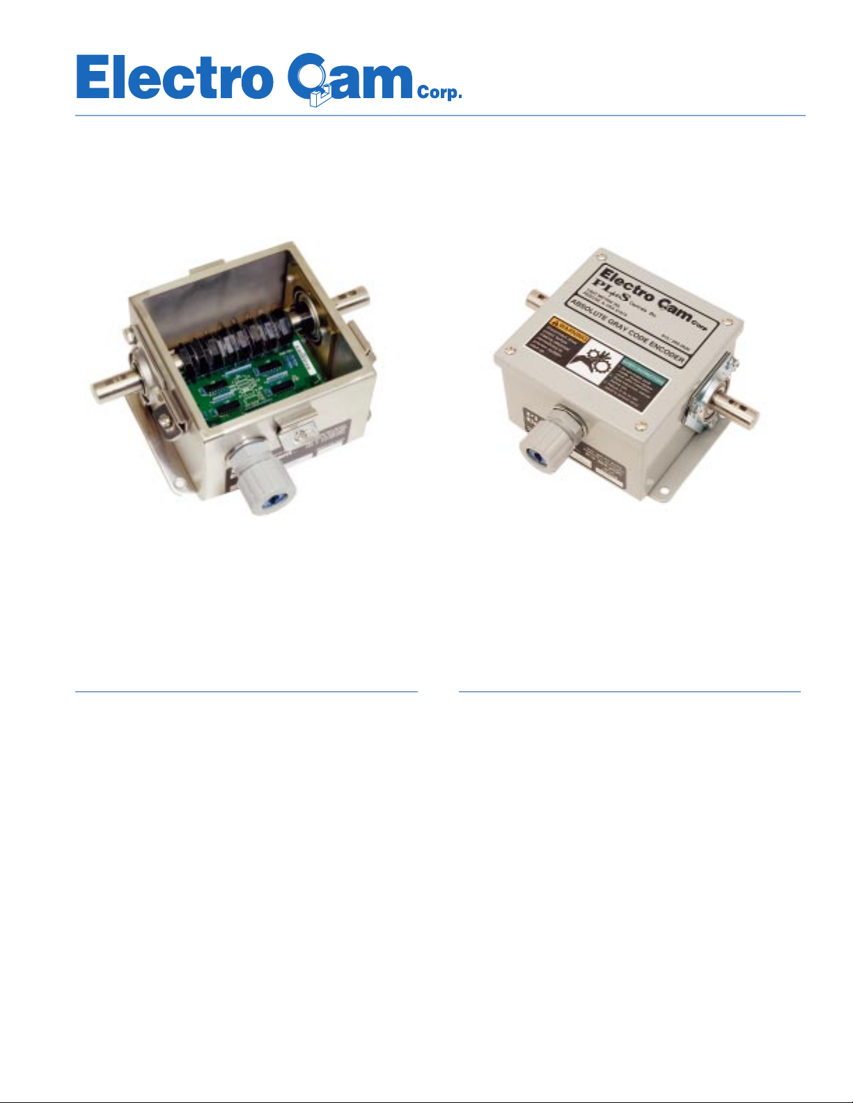
PS-4456/4457 (NEMA 4X)
Easily Interfaced to PLCs Using Standard Digital DC Inputs
Or Directly to Gray Code Modules*
Features
■ Absolute 8 Bit Output
■ Rugged Construction
■ 3/4" Shaft with Ball Bearings
■ NEMA 12 or NEMA 4X
Applications
■ Packaging Machines
■ Pick and Place Operations
■ Assembly Machines
■ Food Processing Equipment
■ Indexing Equipment
PS-4256/4257 (NEMA 12)
General Information
Sinking† or Sourcing† Output — The encoders are available with Sinking† or Sourcing† outputs. Be sure to order
the type that is compatible with the control's input circuits. The use of fast response DC inputs is recommended
to minimize missed fast pulsing encoder outputs.
NEMA 4X Option — The NEMA 4X version of the encoder includes a stainless steel enclosure and shaft,
double sealed ball bearings, and conformal coating on
both sides of the internal circuit board. This version should
be ordered for applications which involve washdowns,
high humidity or corrosive atmospheres.
*
A-B 1771-DL or Similar type modules
13647 Metric Rd • Roscoe, IL 61073 USA • 815-389-2620 • FAX 815-389-3304 • 800-228-5487 (USA & Canada)
†
See page 7 for sinking/sourcing definitions
Page 2

Why 8 Bit Gray Code?
When wiring an encoder to the PLC, the most important thing to
remember is which output is the MSB (Most Significant Bit) and
which is the LSB (Least Significant Bit). If the order is reversed,
or the output wiring is out of order (transposed wires), the value
that you create in the PLC register will not sequence properly.
MSB and LSB are digits of the binary number. An understanding of the different number systems used by logic controllers
(binary, hex, decimal, etc.) is essential to know what these codes
signify.
■ Gray Code is a cyclic or reflected binary code, specifi-
cally designed for positioning information. In a Gray Code
number only one-digit changes at a time. In a binary number, going from one number to the next may have many
of its digits change.
The cyclic change is created by the relationship of the 8
pulse disks that turn the encoder OFF and ON. (See
Figure 6, page 6.)
■ Most Significant Bit refers to the binary code (Gray
Code) digit that is on the far left when written out. This
digit changes the least as the binary number goes from
0 to 255.
■ Least Significant Bit refers to the binary code (Gray
Code) digit that is on the far right when written out. This
digit changes the most as the binary number goes from
0 to 255.
Absolute Position Decoding — The 8 Bit Gray Code
signal always represents the current position of the encoder shaft. The PLC cannot get out of sync with the
present encoder position — not even when the encoder
shaft is turned while power is off to the controller.
8 Bit Resolution (256 increments) — The revolution of
the encoder shaft is divided into 256 uniform increments.
Each increment is 1.4 degrees wide, which allows any
machine position to be known within ±0.7 degrees. This
is appropriate resolution for many applications, especially
when PLC scan times are taken into account (@ 60 RPM,
a 10 mSec scan time equates to 3.6 degrees of motion
between scans).
Error Free Decoding — Only one of the bits changes
state when the encoder shaft rotates, eliminating the need
for sophisticated latching and/or handshaking circuitry between the encoder and the PLC. Standard DC input cards
are used to interface with the encoder. The only special
programming needed is 8 exclusive-ORed (XOR) ladder
rungs.
RPM / Response Considerations
The operating speed and resolution required of the application
must be considered when interfacing the Gray Code encoder
directly to a PLC or other control device. The scan speed and/or
hardware response will cause delays that can reduce the overall
system response and resolution. Where full 8 bit resolution is
required at higher speeds, the use of an Electro Cam PL
µS
(Programmable Limit Switch) is recommended.
Values might not be true for certain fast response PLC inputs.
Faster response times are dependent on hardware.
Scan Time / Maximum RPM / Degrees Per Scan
Scan Time Max RPM @ 30 RPM @ 100 RPM Scan Time Max RPM @ 30 RPM @ 100 RPM
1 mSec 234 0.18 0.60 20 mSec 11 3 6 12.0
5 mSec 46 0.9 3.0 25 mSec 9 4.5 15.0
10 mSec 23 1.8 6.0 30 mSec 7 5.4 18.0
15 mSec 15 2.7 9.0 40 mSec 5 7.2 24.0
The table above indicates the maximum RPM that the encoder can be turning for all 256 positions to be decoded each revolution for the corresponding scan time.
Exceeding the indicated RPM will result in encoder shaft positions being skipped by the control. It is acceptable to skip encoder positions when 8 bit resolution is not
required. Worst case output response = 2 Scans + Hardware response.
Refer to the above chart to compare machine RPM to the values
listed on the chart. If speed exceeds the value, the PLC will not
"see" certain Gray Code values. Miscalculation of the output value
will occur.
If a bit is on for 30 µSec, and the scan time is 10 mSec, the
Deg / Scan Deg / Scan Deg / Scan Deg / Scan
Figure 1
When machine speed rises above a certain level, several factors need to be considered:
■ What is the scan time of the PLC program?
■ What is the response time of the input module?
■ What is the integer value that is being used, and is it de-
pendent on several of the least significant bits?
processor will not see that bit (or combination of bits). If the input
module's response time is longer than the bit, or bits on time, the
module will not react to the input. All of these factors show up as
non-sequencing position values, or outputs that are not performing properly.
2
Page 3
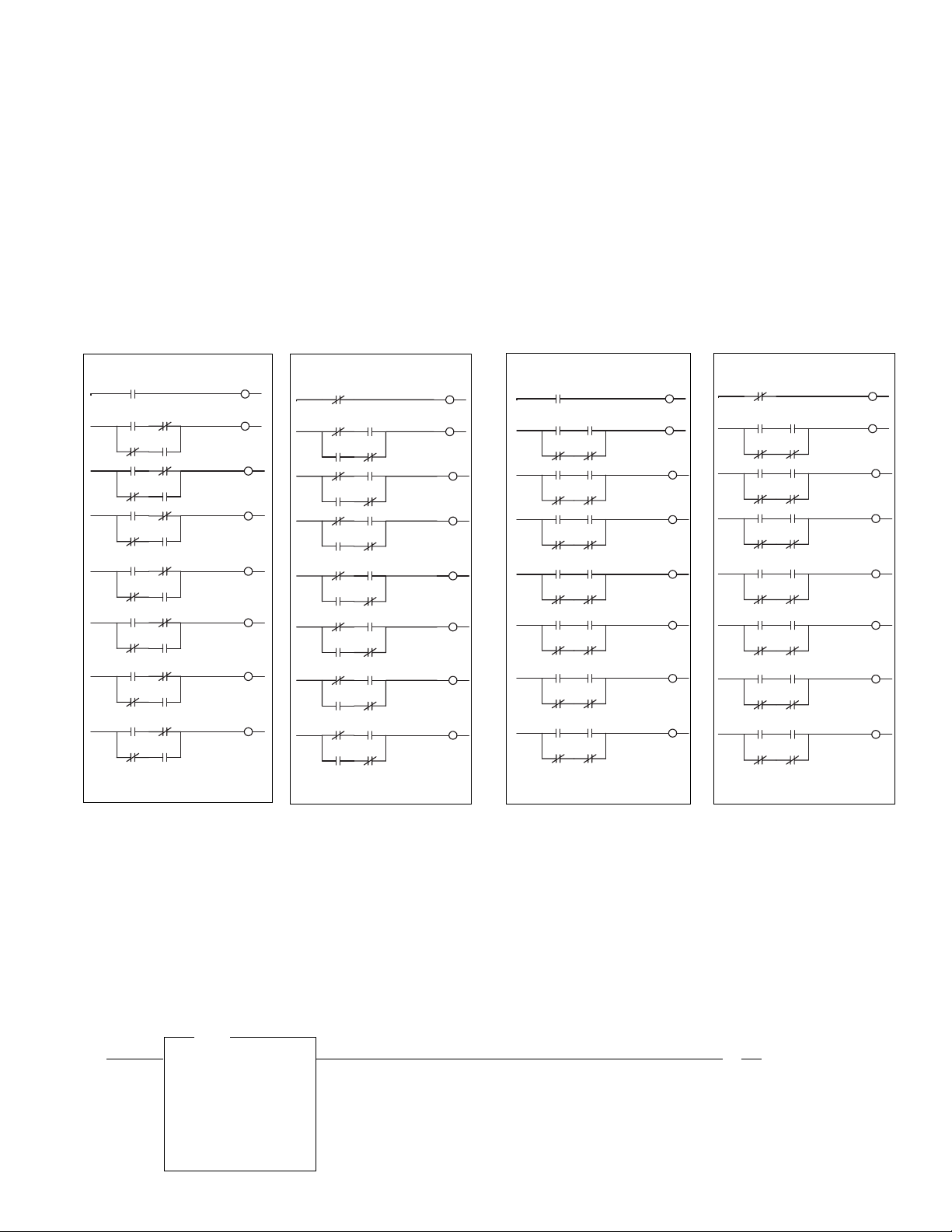
Decoding Gray Code?
The Ladder Programming examples shown below apply
for all Gray Code Encoder models. The examples show
how to convert the 8 Bit Gray Code output signal (G0-G7)
of the encoder to a binary number (B0-B7) during each
scan of the PLC. The value of the Binary result will always be in the range of 0 - 255 because the 8 bit encoder
divides each revolution into 256 uniform increments. Ladder rungs which follow the conversion can compare the
rotary position value to known positions for control of
machine devices that must operate at specific positions
within the overall machine cycle. The rotary position of
Models DDN & DDP
CLOCKWISE ROTATION
G7
B7 G6
G6B7
B6 G5
G5B6
B5 G4
G4B5
B4 G3
G3B4
B3 G2
G2B3
B2 G1
G1B2
B1 G0
G0B1
DRAWING L-1
B7
B6
B5
B4
B3
B2
B1
B0
COUNTER-CLOCKWISE ROTATION
G7
B7 G6
G6B7
B6 G5
G5B6
B5 G4
G4B5
B4 G3
G3B4
B3 G2
G2B3
B2 G1
G1B2
B1 G0
G0B1
DRAWING L-2
B7
B6
B5
B4
B3
B2
B1
B0
the machine cycle can also be used to gate input sensors
and shift register functions.
Converting Gray Code to Binary involves a sequence of
"Exclusive OR" operations. It is simple to program this
same conversion logic in other programming languages
besides ladder logic. In addition to decoding the rotary
position of the encoder, controls with arithmetic capability
can be programmed to perform direction reversal, position offset and re-zero functions, as well as convert the
position value to degrees for ease of monitoring and setup.
Model DDH
COUNTER-CLOCKWISE ROTATION
G7
B7 G6
G6B7
B6 G5
G5B6
B5 G4
G4B5
B4 G3
G3B4
B3 G2
G2B3
B2 G1
G1B2
B1 G0
G0B1
DRAWING L-3
B7
B6
B5
B4
B3
B2
B1
B0
CLOCKWISE ROTATION
G7
B7 G6
G6B7
B6 G5
G5B6
B5 G4
G4B5
B4 G3
G3B4
B3 G2
G2B3
B2 G1
G1B2
B1 G0
G0B1
DRAWING L-4
B7
B6
B5
B4
B3
B2
B1
B0
Use a limit test function to program a pulse in the PLC. The limit test uses a test reference (in this case the integer
register that the Gray Code is going into), and compares it to see if it is between a lower limit and an upper limit. If the
integer value is between the lower limit (ON setpoint), and the upper limit (OFF setpoint), the rung is true and an output
is turned on. If the integer value does not fall between the upper and lower limits, the rung is false, and nothing happens.
For every output pulse to occur, a different limit test must be programmed with the appropriate limits. Reminder: The
limit values are position values, not degrees.
PLC
Output
LIM
Limit Test
Low Lim 107
107<
Test N7:0
0<
High Lim 128
128<
3
O:2.0
( )
0
Page 4

Gray Code — Error Free Decoding
The Gray Code chart below
(Figure 2)
shows the bit patterns that are used to represent all 256 encoder positions.
It can be seen on this chart that from any position to any
adjacent position, only 1 bit changes state. This ensures
that the encoder inputs can be read by the control at any
point in time (even during a transition) without error.
Consider the following comparison to Binary Code:
INC DEG GRAY CODE BINARY
127 178.6 01000000 01111111
128 180.0 11000000 10000000
When Gray Code advances from increment 127 to 128,
only 1 of the 8 bits changes state — bit 8. When Binary
Code advances from increment 127 to 128, all 8 bits
change states. Sampling the Binary bits during this transition could result in a very large decoding error. Sampling
the Gray Code bits during this transition would yield either
127 or 128, depending only on bit 8.
Refer to the table below to understand the relationship
between the
numbers
increment
(integer),
degrees
and
binary
. Use this table as a guide for setup and trouble-
shooting your Gray Code system.
■ INC (increment) column represents the integer value
to which the Gray Code is equal. The increments
are 0 to 255 (256 total) that repeat or cycle. (At 255,
the next number change is 0, increment to 255, then
repeat the cycle over again).
■ DEG (degree) column represents the actual degree
position that the Gray Code is indicating.
■ Gray Code column shows the Gray Code value
for that particular position. This Gray Code binary
number is the same as the Gray Code inputs status,
1 = ON and 0 = OFF.
Because the Gray Code value is also a graphic representation of the input status, it is an invaluable tool in
checking the position or troubleshooting.
INC DEG GRAYCODE
0 0.0 00000000
1 1.4 00000001
2 2.8 00000011
3 4.2 00000010
4 5.6 00000110
5 7.0 00000111
6 8.4 00000101
7 9.8 00000100
8 11.3 00001100
9 12.7 00001101
10 14.1 00001111
11 15.5 00001110
12 16.9 00001010
13 18.3 00001011
14 19.7 00001001
15 21.1 00001000
16 22.5 00011000
17 23.9 00011001
18 25.3 00011011
19 26.7 00011010
20 28.1 00011110
21 29.5 00011111
22 30.9 00011101
23 32.3 00011100
24 33.8 00010100
25 35.2 00010101
26 36.6 00010111
27 38.0 00010110
28 39.4 00010010
29 40.8 00010011
30 42.2 00010001
31 43.6 00010000
32 45.0 00110000
33 46.4 00110001
34 47.8 00110011
35 49.2 00110010
36 50.6 00110110
37 52.0 00110111
38 53.4 00110101
39 54.8 00110100
40 56.3 00111100
41 57.7 00111101
42 59.1 00111111
43 60.5 00111110
44 61.9 00111010
INC DEG GRAYCODE
45 63.3 00111011
46 64.7 00111001
47 66.1 00111000
48 67.5 00101000
49 68.9 00101001
50 70.3 00101011
51 71.7 00101010
52 73.1 00101110
53 74.5 00101111
54 75.9 00101101
55 77.3 00101100
56 78.8 00100100
57 80.2 00100101
58 81.6 00100111
59 83.0 00100110
60 84.4 00100010
61 85.8 00100011
62 87.2 00100001
63 88 6 00100000
64 90.0 01100000
65 91.4 01100001
66 92.8 01100011
67 94.2 01100010
68 95.6 01100110
69 97.0 01100111
70 98.4 01100101
71 99.8 01100100
72 101.3 01101100
73 102.7 01101101
74 104.1 01101111
75 105.5 01101110
76 106.9 01101010
77 108.3 01101011
78 109.7 01101001
79 111.1 01101000
80 112.5 01111000
81 113.9 01111001
82 115.3 01111011
83 116.7 01111010
84 118.1 01111110
85 119.5 01111111
86 120.9 01111101
87 122.3 01111100
88 123.8 01110100
89 125.2 01110101
8 Bit Gray Code Table
INC DEG GRAYCODE
90 126.6 01110111
91 128.0 01110110
92 129.4 01110010
93 130.8 01110011
94 132.2 01110001
95 133.6 01110000
96 135.0 01010000
97 136.4 01010001
98 137.8 01010011
99 139.2 01010010
100 140.6 01010110
101 142.0 01010111
102 143.4 01010101
103 144.8 01010100
104 146.3 01011100
105 147.7 01011101
106 149.1 01011111
107 150.5 01011110
108 151.9 01011010
109 153.3 01011011
110 154.7 01011001
111 156.1 01011000
112 157.5 01001000
113 158.9 01001001
114 160.3 01001011
115 161.7 01001010
116 163.1 01001110
117 164.5 01001111
118 165.9 01001101
119 167.3 01001100
120 168.8 01000100
121 170.2 01000101
122 171.6 01000111
123 173.0 01000110
124 174.4 01000010
125 175.8 01000011
126 177.2 01000001
127 178.6 01000000
128 180.0 11000000
129 181.4 11000001
130 182.8 11000011
131 184.2 11000010
132 185.6 11000110
133 187.0 11000111
134 188.4 11000101
INC DEG GRAYCODE
135 189.8 11000100
136 191.3 11001100
137 192.7 11001101
138 194.1 11001111
139 195.5 11001110
140 196.9 11001010
141 198.3 11001011
142 199.7 11001001
143 201.1 11001000
144 202.5 11011000
145 203.9 11011001
146 205.3 11011011
147 206.7 11011010
148 208.1 11011110
149 209.5 11011111
150 210.9 11011101
151 212.3 11011100
152 213.8 11010100
153 215.2 11010101
154 216.6 11010111
155 218.0 11010110
156 219.4 11010010
157 220.8 11010011
158 222.2 11010001
159 223.6 11010000
160 225.0 11110000
161 226.4 11110001
162 227.8 11110011
163 229.2 11110010
164 230.6 11110110
165 232.0 11110111
166 233.4 11110101
167 234.8 11110100
168 236.3 11111100
169 237.7 11111101
170 239.1 11111111
171 240.5 11111110
172 241.9 11111010
173 243.3 11111011
174 244.7 11111001
175 246.1 11111000
176 247.5 11101000
177 248.9 11101001
178 250.3 11101011
179 251.7 11101010
INC DEG GRAYCODE
180 253.1 11101110
181 254.5 11101111
182 255.9 11101101
183 257.3 11101100
184 258.8 11100100
185 260.2 11100101
186 261.6 11100111
187 263.0 11100110
188 264.4 11100010
189 265.8 11100011
190 267.2 11100001
191 268.6 11100000
192 270.0 10100000
193 271.4 10100001
194 272.8 10100011
195 274.2 10100010
196 275.6 10100110
197 277.0 10100111
198 278.4 10100101
199 279.8 10100100
200 281.3 10101100
201 282.7 10101101
202 284.1 10101111
203 285.5 10101110
204 286.9 10101010
205 288.3 10101011
206 289.7 10101001
207 291.1 10101000
208 292.5 10111000
209 293.9 10111001
210 295.3 10111011
211 296.7 10111010
212 298.1 10111110
213 299.5 10111111
214 300.9 10111101
215 302.3 10111100
216 303.8 10110100
217 305.2 10110101
218 306.6 10110111
219 308.0 10110110
220 309.4 10110010
221 310.8 10110011
222 312.2 10110001
223 313.6 10110000
224 315.0 10010000
INC DEG GRAYCODE
225 316.4 10010001
226 317.8 10010011
227 319.2 10010010
228 320.6 10010110
229 322.0 10010111
230 323.4 10010101
231 324.8 10010100
232 326.3 10011100
233 327.7 10011101
234 329.1 10011111
235 330.5 10011110
236 331.9 10011010
237 333.3 10011011
238 334.7 10011001
239 336.1 10011000
240 337.5 10001000
241 338.9 10001001
242 340.3 10001011
243 341.7 10001010
244 343.1 10001110
245 344.5 10001111
246 345.9 10001101
247 347.3 10001100
248 348.8 10000100
249 350.2 10000101
250 351.6 10000111
251 353.0 10000110
252 354.4 10000010
253 355.8 10000011
254 357.2 10000001
255 358.6 10000000
Figure 2
4
Page 5

Wiring
Figure 3
NEMA 12
Dimensions
NEMA 4X
Figure 4
5
Figure 5
Page 6

Specifications
General NEMA 12 NEMA 4X
Ambient Temp. 0 - 60 Degrees C 0 - 60 Degrees C
Enclosure JIC - 16 Ga Steel JIC - 16 GA Stainless
Shaft Dia. / Material 3/4" Stainless Steel 3/4" Stainless Steel
Bearings 3/4" Sealed Ball Bearing 3/4" Double Sealed Ball
Conformal Coating Component Side of PCB Both Sides of PCB
Electrical Sourcing
Input Voltage 12 - 30 VDC 12 - 30 VDC
Output Voltage 12 - 30 VDC 3 - 30 VDC
Output Current (each bit) 50 mA 50 mA
Output Logic Type High True Low True or High True
†
See page 7 for sinking/sourcing definitions
The 8 Bit Gray Code Encoder Output Chart (
Figure 6
†
Sinking
) shows the transitions of each of the 8 bits as the encoder rotates
†
from 0 to 360 degrees. The output bits are phased so that only one bit changes state at each of the 256 increments.
The pulse disc which operates bit 0 (least significant) has 64 uniformly spaced slots, bit 1 has 32 uniformly spaced
slots, bit 2 has 16 uniformly spaced slots, and so on. The 8 bit output of the encoder is always one of the 256 bit
patterns shown in the table on page 4
(Figure 2)
and always represents the current position of the encoder shaft. For
this reason, the control cannot get out of sync with the encoder. High speed count cards that use incremental encoders are NOT absolute and require marker pulses, or other reference signals, for position synchronization.
Figure 6
6
Page 7

Encoder Part Numbers
NEMA
1000 RPM MAX 2000 RPM MAX Output Type Rating
PS - 4256 - 12 - DDP PS - 4257 - 12 - DDP Sourcing
†
12
PS - 4256 - 12 - DDN PS - 4257 - 12 - DDN Sinking† (Low True)* 12
PS - 4256 - 12 - DDH PS - 4257 - 12 - DDH Sinking† (High True)* 12
PS - 4456 - 12 - DDP PS - 4457 - 12 - DDP Sourcing
†
4X
PS - 4456 - 12 - DDN PS - 4457 - 12 - DDN Sinking† (Low True)* 4X
PS - 4456 - 12 - DDH PS - 4457 - 12 - DDH Sinking† (High True)* 4X
*High True = Current Flow
Low True = No Current Flow
Accessories
PS - 4300 - 03 - XXX (XXX = Length in Feet): 10 Conductor #22 gauge shielded (foil and braid) cable for use with encoders. Cut to
specified length, stripped, tinned, connectors attached to shield.
EC - 8001 - XXX - XXX (X's for pitch and # of teeth): Sprocket disengagement clutch allows encoder to be rotated without turning the
chain which drives the encoder. Call for more information.
†
SINKING or SOURCING (as pertaining to Electro Cam Corp. products)
Sinking
means that when the logic is true and the output (or input device) is ON, the output (or input device) is providing a DC
common or ground to the connected device.
Sourcing
means that when the logic is true and the output (or input device) is ON, the output (or input device) is providing a +DC
voltage to the connected device.
This information is important when interfacing an Electro Cam Corp. product with another electronic device. If you are using an
Electro Cam Corp. product input to an Allen-Br adley 1746-IN16 “sinking” input card* or similar A-B de vice, y ou hav e to supply a +DC
voltage (Electro Cam Corp.
Sourcing
output) to this card, NOT a DC common or ground. In these cases,
Sinking
is what the card
does with the input voltage; sinks it to common or ground.
* Other manufacturers include, b ut not limited to: Koyo (formerly GE Series 1, Texas Instruments, or Siemens SIMATIC PLS’s) that use descriptions
similar to Allen-Bradley.
7
Page 8

Electro Cam Corp. is highly experienced in supplying
automation solutions to a variety of industrial machinery.
For assistance with your application, please call us.
800-228-5487
Copyright © 2000
All Rights Reserved
Neither this document nor any part may be reproduced or transmitted in
any form or by any means without permission in writing from the publisher.
, PLµS, SLIMLINE, and PLµSNET are all registered trademarks of
201 07/00
13647 Metric Rd • Roscoe, IL 61073 USA • Web Site: http://www.electrocam.com • email: ecam@electrocam.com
 Loading...