

Page 1
PL
µ
S
Controls Div.
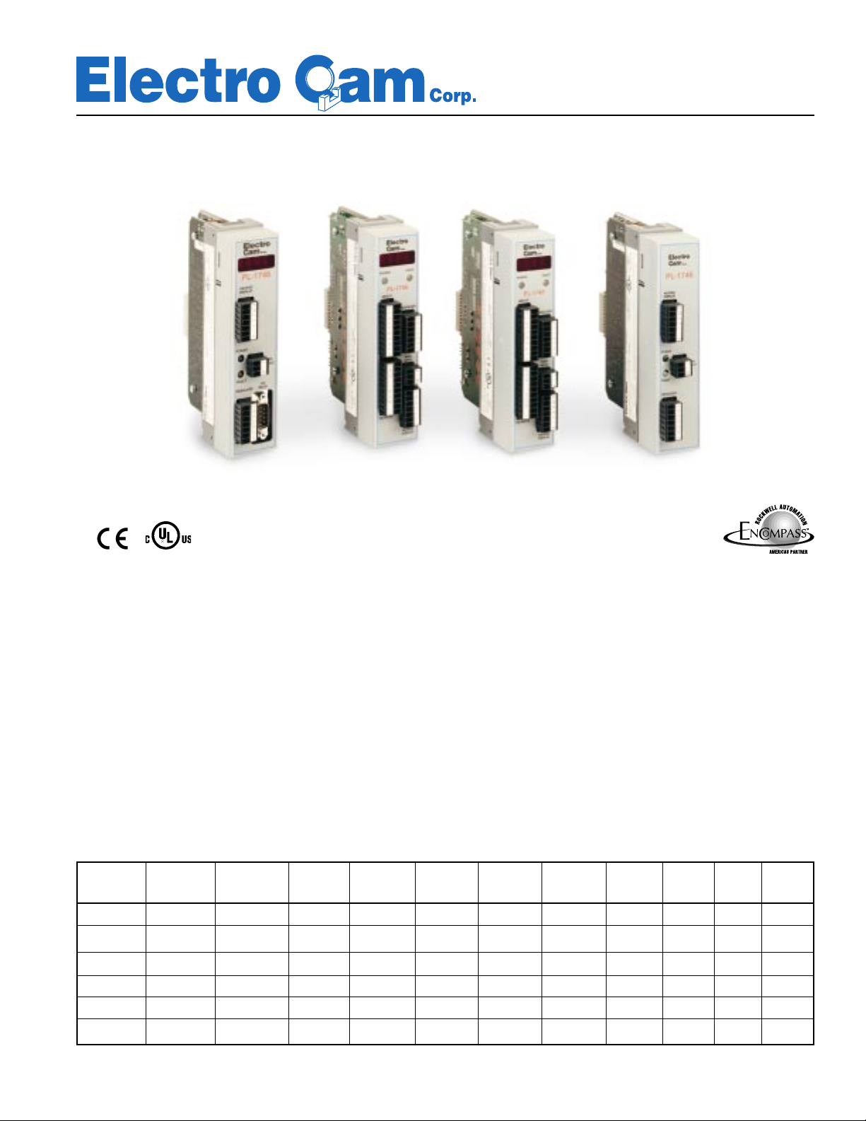
PL-1746 Series
PLµS® Plug-In Modules for the Allen-Bradley SLC-500 PLC
PL-1746-C01
The PLµS PL-1746 Series Plug-In Modules for Allen-
Bradley PLC’s, incorporate advanced PLS functions in
a 1746 I/O module package.
The PLµS Plug-In Modules provide 12 bit absolute position, and accurate control of functions at high speeds,
based on rotary position input. They complement the
control capabilities of the PLC by performing tasks that
typically must occur much faster than a normal PLC scan
cycle.
PL-1746-C02
PL-1746 Series Features
PL-1746
Model
C01
C02-E1
C02-R1
C03-E1
C03-R1
C04
12 bit Leading/ 2 Analog 8 Sinking/ 32 Solid State 6 Sinking 6 Sourcing 2 Analog Onboard Encoder Resolver
Resolution Trailing Speed Backplane Sourcing Relay Output DC Outputs DC Outputs Outputs Display Based Based
❄❄❄❄❄ ❄❄ ❄
❄❄❄❄ ❄ ❄❄
❄❄❄❄ ❄ ❄ ❄
❄❄❄❄ ❄ ❄❄
❄❄❄❄ ❄ ❄ ❄
❄❄❄ ❄
Compensation Outputs DC Inputs via I/O Rack Onboard Onboard
PL-1746-C03
In addition to providing precise control of events based
on rotary position, these modules incorporate high speed
control logic and automatic speed compensation, independent of the PLC scan. Output Groups and High
Speed Logic Modes move beyond standard PLS functionality to give the user powerful tools that solve control problems accurately and at high speeds.
Programming of the PL-1746 modules may be done
through the backplane or through the Electro Cam Corp.
model 6400 keypad/display.
PL-1746-C04
13647 Metric Rd • Roscoe, IL 61073 USA • 815-389-2620 • FAX 815-389-3304 • 800-228-5487 (USA & Canada)
Page 2
Standard PL-1746 Series Features
■ Non-Volatile Memory - configurations
saved when power is interrupted.
■ Automatic leading & trailing edge speed
compensation - to advance/retard output channel timing to compensate for
■ Absolute position with high resolution
(Up to 4096 increments per revolution)
■ 48 available programs - active pro-
grams selected through the backplane
or via the Electro Cam Corp. 6400 se-
ON/OFF delay in valves and other devices.
■ 2 levels of motion detection - to enable/
disable speed critical machine functions.
ries keypad/display.
■ 4 timed outputs for controlling time criti-
■ Complete module status available
cal functions initiated by position.
through the backplane.
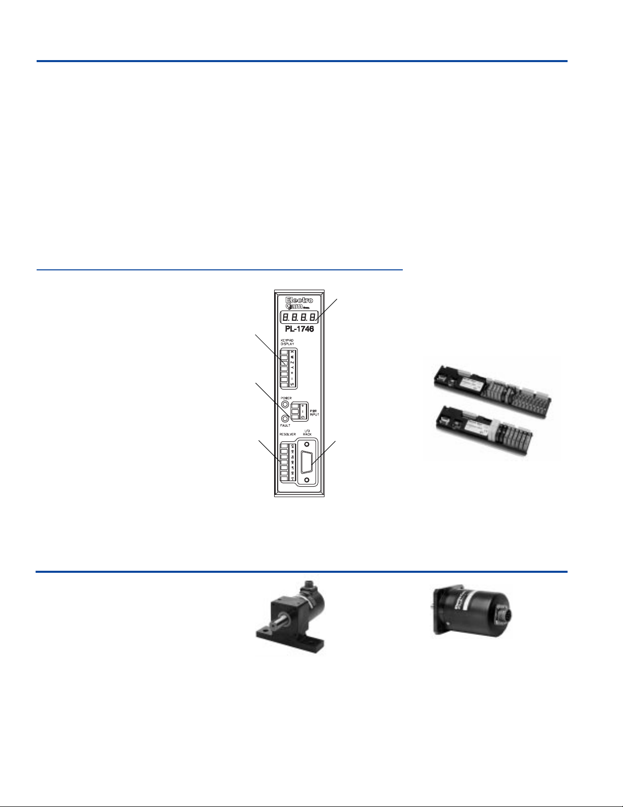
PL-1746-C01 Plug-In Module
■ Up to 32 PLS output channels avail-
able through 1746 backplane. All
channels are available to use either
with the Electro Cam Corp. I/O rack
(High Speed/Real World), or any 1746
discrete output module.
■ Real world, high speed I/O available
via either an 8 input/8 output, or an 8
input/16 output external DIN mount
rack.
Keypad/Display
Power Input
■ Output Groups and Operating Modes
- allows high speed logic to be done in
the PLS, separate from the PLC scan.
■ Able to connect up to 2 Electro Cam
Corp. Model 6400 keypad/displays for
remote adjustment.
■ Ability to access user selected param-
eters while operating in an Allen-Bradley remote I/O chassis.
LED Display
The PS-4108-13-L08 and PS-4108-13-L16 I/O racks
provide inputs, analog outputs, and digital power
outputs (requiring SLIMLINE™ solid state relays) for
the PL-1746-C01 PLµS plug-in modules.
■ Up to 32 digital plus 2 analog outputs
available.
(Requires two racks, 16 I/O per
■ SLIMLINE™ module outputs: AC, DC
rack)
Resolvers
Electro Cam Corp. Resolvers are designed for rugged industrial applications.
They feature dual bearing construction
(except the 5212 model), and come in a
variety of mounting styles and shaft
sizes. Some resolver configurations are
shown here.
See Price List (Lit. #202) for complete
listing of part numbers and specifications.
Resolver
PL-1746-C01
PS-5275-11-ADS
Foot Mount
•3/4" Shaft
•Top side, right side, left side
or rear connection
I/O Rack
(optional)
PS-4108-13-L08 & PS-4108-13-L16 I/O Racks
PS-5238-11-ADR
Flange Mount
•3/8" or 5/8" Shaft
•Top side, right side, left side
or rear connection
2
Page 3
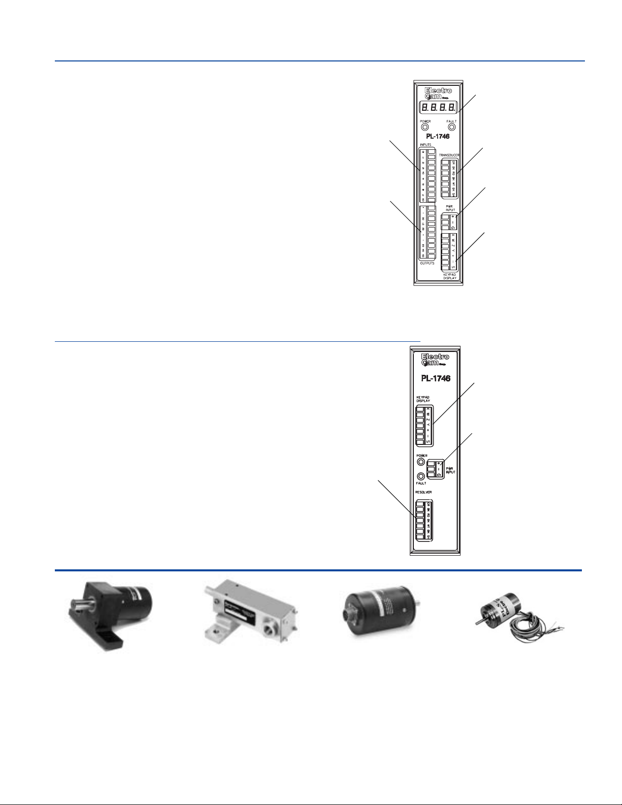
PL-1746-C02/C03 Plug-In Module
■ 6 real world DC outputs, and 8 DC inputs mounted on the front of
the PL-1746 module.
(-C02 = sourcing† outputs, -C03 = sinking† outputs)
■ Up to 32 PLS output channels available through the 1746 back-
plane.
■ 2 analog values based on speed, available through the backplane.
These are "tunable" to a specific machine speed range.
Inputs
LED Display
Resolver
or
Encoder
Optional Features
■ Incremental Encoder input.
■ Shift register with 256 shifts.
■ Output assignment allowing the user to choose which six (6)
channels are the real world power outputs.
All other features of the PL-1746-C02/C03 models are the same as
those for standard PL-1746 series modules.
PL-1746-C04 Plug-In Module
■ Up to 32 PLS output channels available through the 1746 back-
plane.
■ 2 analog outputs available through the backplane.
All other features of the PL-1746-C04 model are the same as those
for standard PL-1746 series modules.
Power Input
Outputs
Keypad/Display
PL-1746-C02/C03
Keypad/Display
Power Input
Resolver
PS-5275-051-ADL
Foot Mount Geared
•3/4" Shaft
•5:1 Gear Ratio
•Top side, right side or
PS-5262-11-CTG
Stainless Steel
•5/8" Shaft
•Left side or right side
connection
left side connection
•Available in ratios 2:1 thru 36:1 (Consult Factory for availability)
PL-1746-C04
PS-5238-11-SDR
Servo Mount
•3/8" Shaft
•Top side, right side,
left side or rear connection
3
PS-5212-11-SVW
Unhoused Servo
Mount
•.120" Shaft
•Standard size 11
†
See page 4 for sinking/sourcing definitions.
Page 4

Plug-In Module
Plug-In Module
Part Number Breakdown
P L - X X X X - XXX - X X - X
PL = Plugs into backplane
Utilizes Allen-Bradley
technology.
PLA TFORM TYPE
1746 = SLC 500
SUB-CATEGORY
C01 = Display, 32 Real World I/O with
External I/O racks
C02 = Display, Built-in 8 Inputs and 6
Sourcing† DC Outputs, 1.5 A
C03 = Same as C02, except with
Sinking† outputs
C04 = No Display, No Real World I/O
TYPE TRANSDUCER
R - Resolver
E - Encoder
NUMBER OF
TRANSDUCERS
1 = One
OPTIONS
S = Shift Register & Output
assignment feature
Resolver
Part Number Breakdown
P S - 5 2 X X - X X X - X X X - X
PLµS
Part Number
Typical Systems
Component(s) Qty. Part Number
PL-1746-C01 System
C01 Plug-In Module (1) PL-1746-C01-R1
Resolver (1) PS-5275-11-ADR
Resolver Cable (1) PS-5300-01-010
Keypad/Display (1) PS-6400-24-001
Keypad-to-controller cable(s) (1) PS-6300-01-005
I/O Rack (1) PS-PS-4108-13-L08
I/O Rack Cable (1) PS-4308-10-005
SLIMLINE™ Output Modules (16) EC-ODC060-3
SLIMLINE™ Analog Modules (2) EC-SANL-010V
PL-1746-C02 System (C03 for †Sinking)
C02/C03 Plug-In Module (1) PL-1746-C02-R1
Resolver (1) PS-5275-11-ADR
Resolver Cable (1) PS-5300-01-010
Keypad/Display (1) PS-6400-24-001
Keypad-to-controller cable(s) (1) PS-6300-01-005
PL-1746-C04 System
C04 Plug-In Module (1) PL-1746-C04-R1
Resolver (1) PS-5275-11-ADR
Resolver Cable (1) PS-5300-01-010
Keypad/Display (1) PS-6400-24-001
Keypad-to-controller cable(s) (1) PS-6300-01-005
Resolver
SHAFT SIZE
12 - 1/8 DIA.
15 - 15 mm DIA.
20 - 20 mm DIA.
38 - 3/8” DIA., 2.06” Bolt Flange
62 - 5/8” DIA., 2.25” Bolt Flange
75 - 3/4” DIA.
RATIO
11 - Standard 1:1 (Note: 3rd digit
not used on Standard 1:1)
021 - Geared 2:1 - Ext. shaft to
internal resolver shaft
thru
361 - Geared 36:1 - Ext. shaft to
internal resolver shaft
Various ratios available,
contact Factory.
HOUSING
A - Can housing w/flange
or foot endbells.
C - Stainless steel
square housing.
E - 74 mm bolt spacing,
flange mount
S - Servo mount
(.12 = size 11;
.38 = size 25 )
TYPE OF CABLE CONNECTION
D - Military bayonet style connector
T - Terminal strip with NO conduit
entrance
V - No connector, just stripped &
tinned wires
S - Sealed connector — screw type
Note: Part # PS-5903-01-001
conduit entrance for
terminal strip models
sold separately.
LOCATION OF CABLE CONNECTION
W- With stripped & tinned leads
G - Right (120° from top on “A” housings)
R - Rear (not available on Geared Resolver)
L - Left (120° from top on “A” housings)
S - Side (Top)
OPTION
V - Vertical Mount
Note: Only required
for vertical mounting
of PS-5262-11-CTX
Models.
†
SINKING or SOURCING
( as pertaining to Electro Cam Corp. products )
Sinking
input device) is ON, the output (or input device) is providing a
DC common or ground to the connected device.
Sourcing
(or input device) is ON, the output (or input device) is pro viding a +DC voltage to the connected device.
This information is important when interfacing an Electro Cam
Corp. product with another electronic device. If y ou are using
an Electro Cam Corp. product input to an Allen-Bradle y 1746IN16 “sinking” input card* or similar A-B device, you have to
supply a +DC voltage (Electro Cam Corp.
to this card, NOT a DC common or ground. In these cases,
Sinking
to common or ground.
* Other manufacturers include, but not limited to: Koyo (for-
merly GE Series 1, Texas Instruments, or Siemens SIMATIC
PLS’s) that use descriptions similar to Allen-Bradley.
means that when the logic is true and the output (or
means that when the logic is true and the output
Sourcing
output)
is what the card does with the input voltage; sinks it
4
Page 5

Resolver Dimensions
Foot Mount
With Rear Connector (shown):
PS-5275-11-ADR
With Side Connector:
PS-5275-11-ADS
Cable:
PS-5300-01-XXX where "XXX" is length in feet.
Flange Mount
With Rear Connector (shown):
PS-5238-11-ADR
With Side Connector:
PS-5238-11-ADS
Cable:
PS-5300-01-XXX where "XXX" is length in feet.
Stainless Steel
Horizontal Mount (shown):
PS-5262-11-CTG (with right connector)
With Left Connector:
PS-5262-11-CTL
Vertical Mount (Shaft up)
PS-5262-11-CTG-V (with right connector)
PS-5262-11-CTL-V (with left connector)
0.749/
0.747"
19.02/
18.97 mm
0.375/
0.374"
9.53/
9.50 mm
.625/
.624" dia.
15.88/
15.85 mm
Cable:
PS-5300-02-XXX where "XXX" is length in feet.
Unhoused Servo Mount
Size 11, .120" Shaft:
PS-5212-11-SVW
Contact the Factory for detailed specifications on other available resolvers.
For horizontal applications
5
Page 6

PL-1746 Specifications
Plug-In Module PL-1746-C01-R1 PL-1746-C02-E1-S PL-1746-C04-R1
Part Numbers PL-1746-C02-R1
PL-1746-C03-E1-S
PL-1746-C03-R1
Electrical
Input Power
Backplane Power
I/O Power
Permanent Memory
Environment
Operating Temp.
Storage Temp.
Humidity
NEMA Rating
20-30 VDC. Keypad/display is
powered from controller.
5VDC @ 500 mA max.
20-30 VDC, 80 mA + 150 mA
per keypad + 230 mA per rack.
Example: Total = 840 mA with 2 keyboards and 2
racks.
Certain types of power supplies employ a self
protection feature called current fold back
limiting. The inrush currents of the high efficiency
switching regulators may cause power supplies to
enter current limit mode. Power supplies with
current fold back limiting should be sufficient to
supply three times the steady state current of the
system.
Inrush current @ 30v, 40 amps max. for 600 µs
(2 keyboards, 2 racks)
EEPROM (no battery required)
0° to 55°C (32° to 131°F)
-40° to 70°C (-40° to 160°F)
95% maximum relative
non-condensing
Keypad/Display: NEMA 4
20-30 VDC. Keypad/display is
powered from controller.
5 VDC @ 500 mA max.
20-30 VDC @ 90 mA max. + 150 mA
per PS-6400 keypad
Certain types of power supplies employ a self
protection feature called current fold back
limiting. The inrush currents of the high efficiency
switching regulators may cause power supplies to
enter current limit mode. Power supplies with
current fold back limiting should be sufficient to
supply three times the steady state current of the
system.
EEPROM (no battery required)
0° to 55°C (32° to 131°F)
-40° to 70°C (-40° to 160°F)
95% maximum relative
non-condensing
Keypad/Display: NEMA 4
5VDC @ 500 mA max.
20-30 VDC @ 80 mA max. + 150 mA
per PS-6400 keypad (include power
supply warning).
EEPROM (no battery required)
0° to 55°C (32° to 131°F)
-40° to 70°C (-40° to 160°F)
95% maximum relative
non-condensing
Keypad/Display: NEMA 4
Physical
Weight
PLµS Module: 0.5 lbs (0.2 kg)
Keypad/Display: 0.5 lbs. (0.2 kg)
Mounting
Controller
Rack
Keypad/Display
Mounts in SLC-500 chassis.
Brackets accept EN-50035 (“G” profile)
or EN-50022 (“Top Hat” profile) DIN Rail
Mounts up to 1000’ from controller. 0
0 to 2 keypads may be connected to
one controller.
Inputs on Rack
DC Inputs
Input ON State Voltage
Input Current
Response
8 sinking† or sourcing† DC inputs,
optically isolated (1st rack only).
10-30 VDC
11 mA @ 24 VDC
2 µs max.
Outputs on Rack
Real World Outupts Up to 16 SLIMLINE™ modules may
Analog Output Up to 2 SLIMLINE™ analog output
be mounted on the rack. Modules
may be any mix of AC, DC, and reed
relay. All modules (except reed relay)
optically isolated.
modules may be mounted on the rack
in addition to the 16 digital modules.
PLµS Module: 0.5 lbs (0.2 kg)
Keypad/Display: 0.5 lbs. (0.2 kg)
Mounts in SLC-500 chassis.
Mounts up to 1000’ from controller. 0
0 to 2 keypads may be connected to
one controller.
PLµS Module: 0.5 lbs (0.2 kg)
Keypad/Display: 0.5 lbs. (0.2 kg)
Mounts in SLC-500 chassis.
Mounts up to 1000’ from controller. 0
0 to 2 keypads may be connected to
one controller.
†
See page 4 for sinking/sourcing definitions.
6
Specifications continued...
Page 7

PL-1746 Specifications (continued)
Plug-In Module PL-1746-C01-R1 PL-1746-C02-E1-S PL-1746-C04-R
Part Numbers PL-1746-C02-R1
PL-1746-C03-E1-S
PL-1746-C03-R1
Outputs On Rack (cont’)
Output Types
Resolution
Update Frequency
Linearity
Set-up
Inputs on Module
DC Inputs
4-20 mA or 0-10 VDC, proportional to RPM
12 bit
10 ms
±0.3% of full scale @ 25°C (77°F)
Offset & full scale RPM are programmable
8 DC inputs, optically isolated,
sinking† or sourcing† in banks of 4.
Input ON State Voltage
Input Current
Response
Outputs on Module
Real World Outputs
Analog Output
Resolution
Update Frequency
Set-up
Operation
Scan Time
Position Resolution
Speed Compensation
Less than 1000 µs typical (exact time
determined by programming)
12 bits (4096 increments)
Programmed in 0.1 msec steps. 16 individually
compensated outputs max. Updated 5 times per
second. Separate leading/trailing edge
compensation standard.
20-30 VDC
11 mA @ 24 VDC
2 µs max.
6 DC outputs @ 1.5A each, 20-30V
Note: -C02 all outputs are SOURCING
-C03 all outputs are SINKING
†
Analog outputs accessible through
backplane only; they are proportional
to RPM.
12 bit
10 ms
Offset & full scale RPM are
programmable
Less than 1000 µs typical (exact time
determined by programming).
12 bits (4096 increments)
Programmed in 0.1 msec steps. 16
individually compensated outputs max.
Separate leading/trailing edge compensation standard.
†
Less than 1000 µs typical (exact
time determined by programming).
12 bits (4096 increments)
Programmed in 0.1 msec steps. 16
individually compensated outputs max.
Updated 5 times per second. Separate
leading/trailing edge compensation
standard.
Output Timeout
Number of Timed Outputs
Multiple Programs
Total Pulse Memory
Pulses per Program
Pulses per Output
Maximum Speed
†
See page 4 for sinking/sourcing definitions.
1.0 ms time base (accuracy: +1,-0 ms)
Four maximum
48 programs standard
1252 pulses standard
512 maximum standard
512 maximum standard
3000 RPM. Note: Pulses generated with Pulse
Train command are not included in pulses per
program or pulses per output counts.
1.0 ms time base (accuracy: +1,-0 ms)
Four maximum
48 programs standard
1252 pulses standard
512 maximum standard
512 maximum standard
3000 RPM.
7
1.0 ms time base (accuracy: +1,-0 ms)
Four maximum
48 programs standard
1252 pulses standard
512 maximum standard
512 maximum standard
3000 RPM. Note: Pulses generated
with Pulse Train command are not
included in pulses per program or
pulses per output counts.
Page 8

Copyright © 2000
All Rights Reserved
Neither this document nor any part may be reproduced or transmitted in
any form or by any means without permission in writing from the publisher.
, PLµS, SLIMLINE, and PLµSNET are all registered trademarks of
This product incorporates patented technology which is licensed by Allen-Bradley Company, Inc. A-B has not technically
approved, nor does it warrant or support this product. All warranty and support for this product and its application is provided
solely by Electro Cam Corp.
SLC-500 is a trademark of Allen-Bradley Company.
299 08/00
13647 Metric Rd • Roscoe, IL 61073 USA • Web Site: http://www.electrocam.com • email: ecam@electrocam.com
 Loading...