

Page 1
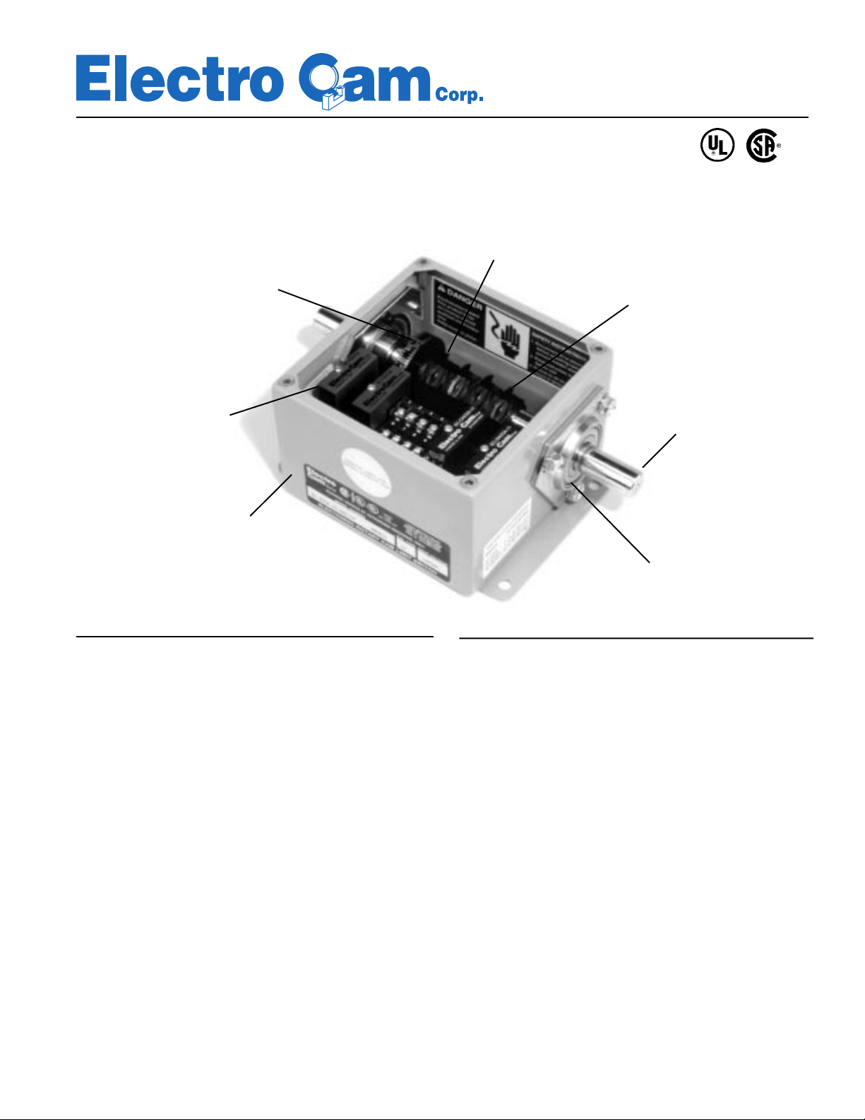
EC-3000/3400 Series
Solid State Rotary Cam Limit Switches
Interrupter Discs and
Photocouplers
Internal
Degree Wheel
and Pointer
Eliminate Contact
Wear and Bounce
Interrupter Discs
Seat Tightly on O-Rings.
Easy-to-Adjust with Wrench.
No Cumbersome Lock Screws
Plug-In
AC, DC, or
Reed Relay
Output Modules
Gasketed NEMA 12
Enclosure on EC-3000;
NEMA 4X Stainless Steel
Enclosure on EC-3400
Description
EC-3000 Series and EC-3400 Series Rotary Cam Limit Switches
use interrupter discs and photocouplers instead of traditional
cams and mechanical limit switches, eliminating contact wear
and bounce. They provide on/off control of devices such as glue
guns, solenoids, air cylinders, or relays on shaft-driven machinery. Electronic Cam Limit Switches can be used as stand-alone
switches, or they can be interfaced to programmable logic controllers (PLC’s) or other logic circuitry.
Although generally used for applications which do not require
setpoint adjustment for speed changes or product changeover,
EC-3000 Series and EC-3400 Series switches can accommodate multiple setpoint schemes by assigning groups of interrupters to different product configurations. For product changeover,
simply activate the appropriate group of interrupters.
Typical applications for EC-3000 Series and EC-3400 Series
switches include cartoners and case packers, palletizers, gluing
machines, high-speed presses, automatic assembly, pick and
place equipment, and similar machinery.
Right, Left, or
Double-Ended Shaft
Configurations
Available
Heavy-Duty
Sealed
Ball Bearings
Features
• Available with 4, 8, or 12 fused, optically-isolated outputs.
• Heavy-duty construction for industrial environments.
• Plug-in modules for AC or DC outputs; replaceable input/
output fuses, easily removed and installed with a needle
nose pliers.
• LED’s indicate output status.
• EC-3000 units housed in NEMA 12 enclosures; EC-3400
units housed in NEMA 4X stainless steel enclosures.
• Sealed ball bearings.
• Internal degree wheel and pointer located on shaft for easy
and accurate adjustment.
• Right, left, or double-ended shaft extensions with a #606
Woodruff key provision; double-ended stainless steel shaft
standard with NEMA 4X models.
• Available options include multi-pulse discs, external degree
wheel and pointer, sprocket disengagement clutch, highvibration models, and special shafts.
• Standard EC-3000 and EC-3400 UL listed, CSA certified;
240 VAC models not UL listed.
13647 Metric Rd • Roscoe, IL 61073 USA • 815-389-2620 • FAX 815-389-3304 • 800-228-5487 (USA and Canada)
Page 2
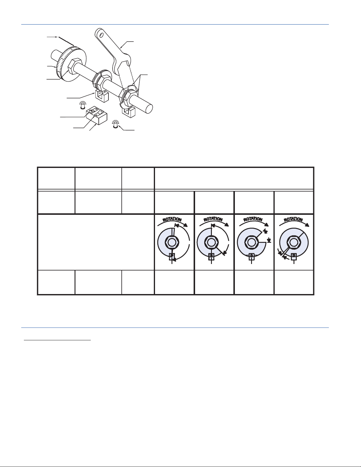
Theory of Operation
Degree Wheel
Pointer
Degree Wheel
Adjustable to
Correspond to
Machine Zero
Photocoupler
0 to 180 Degree Mode
-Light Energized181 to 360 Degree Mode
-Dark Energized-
SWITCH
MODE
0° - 180°
Light
Energized
DIP Switch
Figure 1
ENERGIZED
BY
Photocoupler
Light Beam
-PASSING-
Wrench
for Cam Adjustment
LED Indicator
ON
TIME
Fully
Adjustable
1° to 180°
Interrupter Disc
Halves
From
0° to 170°
ON for 170°
As shown in Figure 1, each output switch is controlled by
two-part interrupter discs which break the beam of light in
a photocoupler. If the DIP switch associated with a
photocoupler is in the “0° to 180°,” or Light Energized mode,
the output will be switched on when the beam is unbroken.
If the DIP switch is in the “181° to 360°,” or Dark Energized
mode, the output will be switched on when the interrupter
breaks the beam.
The gap, or open window in the interrupter is adjusted by
using a wrench to turn the disc halves. Shown below in
Figure 2 is a chart showing a few examples of setting “on”
times, by adjusting the gap and the DIP switch positions.
Disc halves seat tightly to the shaft with O-rings. The discs
are easy to adjust with a wrench, requiring no cumbersome locking screws or other devices.
EXAMPLE
CAM SETTINGS
From
45° to 180°
ON for 135°
From
90° to 135°
ON for 45°
From
312° to 322°
ON for 7°
45°
181° - 360°
Dark
Energized
Photocoupler
Light Beam
-BLOCKED-
Fully
Adjustable
181° to 359°
"0"
From
170° to 0°
ON for 190°
170°
From
180° to 45°
ON for 225°
135°
7°
"0"
"0"
From
135° to 90°
ON for 315°
"0"
From
322° to 315°
ON for 353°
Figure 2
†
SINKING or SOURCING ( as pertaining to Electro Cam Corp. products )
Sinking
common or ground to the connected device.
Sourcing
voltage to the connected device.
This information is important when interfacing an Electro Cam Corp. product with another electronic device. The terms
SOURCING
Bradley 1746-IN16 “sinking” input card* or similar A-B device, you have to supply a +DC voltage to this card, NOT a DC common o r
ground. In these cases,
means that when the logic is true and the output (or input device) is ON, the output (or input device) is providing a DC
means that when the logic is true and the output (or input device) is ON, the output (or input device) is providing a +DC
SINKING /
are not used in the same context by all manufacturers. If you are using an Electro Cam Corp. product input to an Allen-
Sinking
is what the card does with the input voltage; sinks it to common or ground.
* Other manufacturers include, but not limited to: Koyo (formerly GE Series 1, Texas Instruments, or Siemens SIMATIC PLS’s) that use descriptions
similar to Allen-Bradley.
page 2
Page 3
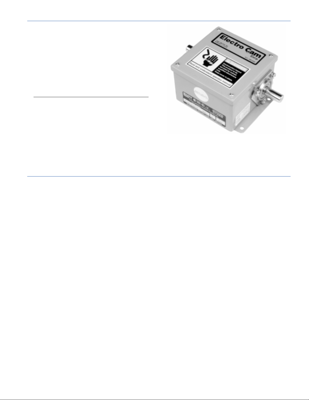
Standard Models
All EC-3000 Series units are housed in NEMA 12 enclosures. All EC-3400 Series units are housed in NEMA 4X
stainless steel enclosures. All units have either right, left,
or double-ended shaft extensions with a #606 Woodruff
Key provision; Nema 4X models have a double-ended
stainless steel shaft. The cover plate on the EC-3400 Series units is secured with clamps to avoid contamination.
Five standard EC-3000 Series and four standard EC-3400
Series models are available:
Model Outputs Standard Shafts*
EC-3004/EC-3404 4 Right, left, or double
EC-3008/EC-3408 8 Right, left, or double
EC-3012/EC-3412 12 Right, left, or double
*See dimensional drawings for shaft illustrations.
Special shafts can be supplied. Please enclose shaft
drawing and specs with your order. All NEMA 4X
units are ONLY available in double-ended shafts.
Model EC-3004-10-ARO
Options
Pulse Generating Discs
Multi-output pulse generating discs are an option offered
for applications requiring multiple outputs per revolution.
These discs are most often used to generate timing pulses
for tachometers, motion detection, glue stitching, or wherever multi-pulse signals are required. Glue stitching patterns on carton and case sealing equipment is an example
of an application that benefits from pulse generating discs.
Standard pulse discs are available with 1, 2, 3, 4, 6, 7, 10,
16, 20, 32, 60, and 64 slots per revolution, allowing for
quick changeover. Pulse generating discs must be ordered
with the unit. The discs are factory mounted on the cam
shaft, and each disc replaces one set of adjustable cams.
See Publication 107B for more detailed information.
Sprocket Disengagement Clutch
The sprocket disengagement clutch is essential in situations where the shaft needs to be easily disconnected from
the sprocket without removing the chain. The clutch not
only allows for disengagement of one station of the machine to check operation without jogging the entire machine, but it simplifies the adjustment of the rotary cam
limit switch. The clutch automatically locks back in the home
position after one revolution. The clutch has a 3/4 inch
bore with the provision for a #606 Woodruff key. There are
five standard and numerous special sprockets
available. See Publication 108B for more detailed information.
External Degree Wheel and Pointer
An internal degree wheel and pointer is included with each
EC-3000 and EC-3400 unit for reference during cam
adjustment. To visually determine shaft position without removing the cover, an optional external degree wheel and
pointer is available. This option must be ordered with the
unit, and requires a double-ended shaft for mounting.
Specify mounting on left- or right-hand shaft (see mounting dimensions), and clockwise or counterclockwise rotation as viewed from end of shaft.
CFX for High Shock / Vibration
For extremely high shock or vibration, such as punch press
applications, a CFX option may be needed on the EC-3000
or EC-3400 units. The CFX option adds clear conformal
coating on both sides of the printed circuit board and removable jumpers replace the DIP switch. The jumpers
eliminate the possibility of intermittent connection to the
DIP switch or the accidental changing of the DIP switch
setting through shock or vibration.
CF for Highly Contaminating Environments
For highly contaminating environments, the CF option may
be ordered with the EC-3000 units. The CF option adds
clear conformal coating to both sides of the printed circuit
board. This option is standard on all EC-3400 units.
page 3
Page 4

Mounting and Shaft Connection
The shaft can be coupled to the machine using a chain and sprocket, timing pulley and
belt, or a direct in-line shaft-to-shaft coupling.
If a shaft-to-shaft coupling is used, Electro Cam Corp. recommends the use of a flexible
coupling. Flexible couplings available through Electro Cam Corp. are listed on the Rotary
Cam Switch Price List, Lit. #111.
Using a solid coupling with shaft misalignment greater than 0.005" (T.I.R.) may
damage the unit. Because of tolerance stackups, this will require shimming of the
individual unit to its mounting surface.
Specifications
Max Speed: 3000 RPM, clockwise or counterclockwise rotation
Max Phase Shift: 1°/1000 RPM
Ambient Temp: 0° to 60°C (32° to 140°F)
Input V oltage: 120 VAC (108 to 132 VAC), 50 or 60 Hz.
12 VDC, 24 VDC or 240 VAC units available
Input Power: EC-3004/EC-3404 3 VA Max
EC-3008/EC-3408 6 VA Max
EC-3012/EC-3412 6 VA Max
Shaft: 3/4" diameter shaft extensions. The shaft is rated at 32,000 PSI yield and necked down to 0.500"
internally. Power transmission through shaft should be based on these figures.
Max Side Load: 100 lbs. at speeds up to 1800 RPM / 200 lbs. at speeds up to 500 RPM
Bearing Life: 10 years (87,660 hours) continuous running with 75 lbs. side load at 1000 RPM
Note: Consult factory if higher speeds or larger loads are required.
Enclosures: EC-3000—NEMA 12 steel housing
EC-3400—NEMA 4X stainless steel housing
Printed Circuit
Board: EC-3000—conformal coating on top only
EC-3400—conformal coating on top and bottom
Net Weight: EC-3004/EC-3404: 9.0 lbs. 4.0 kg
EC-3008/EC-3408: 13.5 lbs. 6.1 kg
EC-3012/EC-3412: 15.0 lbs. 6.8 kg
Output Module Specifications
The EC-3000 Series and the EC-3400 Series units offer plug-in modules for DC, AC, and Reed Relay outputs. One output
module must be purchased for each output desired. For further information, please consult the factory.
DC Output: EC-ODC5, Red
AC Outputs: EC-OAC5A-11, Black/Gray
Output Voltage: 0 to 60 VDC
Output Current: 1.0 Amp @ 35°C (95°F)
Derate 35.7 mA/°C above 35°C (95°F)
DC Output: EC-ODC5A, Red
Output Voltage: 0 to 200 VDC
Output Current: 0.5 Amp
Derate .018 amp/°C above 45°C (113°F)
page 4
Output Voltage: 24 to 132 VAC
Output Current: 0.8 Amp @ 35°C (95°F)
Derate 50 mA/°C above 35°C (95°F)
Reed Relay: EC-ORR5, White
Output Type: Reed Relay Contacts
DC Rating: 0 to 24 VDC
0 to 100 mA DC (resistive loads only)
AC Rating: 0 to 120 VAC
0 to 30 mA AC (resistive loads only)
Page 5

Terminal and Component Identification
The following three drawings are component layouts.
EC-3400 Series Units
All EC-3400 Series units have the same component layout as the EC-3000 Series units except a stainless steel doubleended shaft extension and stainless steel enclosure with clamps to secure the cover are standard.
Figure 3
EC-3004 Unit
1 1/16" Dia. Hole
(For 3/4" Conduit)
Figure 4
EC-3008 Unit
Figure 5
EC-3012 Unit
Degree Wheel
and Pointer
Left-Hand Shaft
Extension Shown
0° to 180°
181° to 360° 181° to 360°
151
5
1 1/16" Dia. Hole
(For 3/4" Conduit)
0° to 180°
6
Interrupter Discs
DIP Switches
Indicator Lights
1/4 Amp Input Fuse
EC-9000-0250
Output Terminals
1
Wireway
234L
Output Modules
1213
11
14
18
1617
15
L6789
19
202122
26252423
1 1/16" Dia. Hole
EC-OAC5A-11 for AC
EC-ODC5 for DC
EC-ODC5A for DC
EC-ORR5 Reed Relay
3 Amp Output Fuses
EC-9000-0003
120 VAC
Input Terminals
(For 3/4" Conduit)
page 5
Page 6

Mounting Dimensions - EC-3004, EC-3008 & EC-3012
Right-Hand or DoubleEnded Shaft Extension
.75"
0
19.1 mm
0.750/0.748"
19.05/19.00 mm
Left-Hand
Shaft Slotted
for Woodruff Key #606
(Customer Supplied)
G
HJ
1 1/16" Dia. Hole
4) Holes
F
E
D
(
0.31" Dia.
7.9 mm
.07"
2
52.6 mm
69.9 mm
(For 3/4" Conduit)
2.75"
4.38"
111.3 mm
L
K
C
B
A
Figure 6
EC-3004, EC-3008 & EC-3012
EC-3004 EC-3008 EC-3012
A 7.50" (190.5 mm) 9.50" (241.3 mm) 11.50" (292.1 mm)
B 6.00" (152.4 mm) 8.00" (203.2 mm) 10.00" (254.0 mm)
C 3.00" (76.2 mm) 3.38" (85.9 mm) 5.00" (127.0 mm)
D 1.94" (49.3 mm) 2.50" (63.5 mm) 2.50" (63.5 mm)
E 6.75" (171.5 mm) 8.75" (222.3 mm) 10.75" (273.1 mm)
F 6.25" (158.8 mm) 8.25" (209.6 mm) 10.25" (260.4 mm)
G 0.88" (22.4 mm) 1.25" (31.8 mm) 1.25" (31.8 mm)
H 4.00" (101.6 mm) 6.00" (152.4 mm) 6.00" (152.4 mm)
J 6.25" (158.8 mm) 8.25" (209.6 mm) 8.25" (209.6 mm)
K 6.00" (152.4 mm) 8.00 (203.2 mm) 8.00" (203.2 mm)
L 1.88" (47.8 mm) 2.25" (57.2 mm) 2.25" (57.2 mm)
Table 1
EC-3004, EC-3008 and EC-3012 Dimensions
Page 7

Figure 7
EC-3404
Mounting Dimensions - NEMA 4X Units
1-1/16" Dia. Hole
(For 3/4" Conduit)
Figure 8
EC-3408 & EC-3412
J
H
G
F
E
2.07"
52.6 mm
D
1-1/16" Dia. Hole
(For 3/4" Conduit)
Table 2
EC-3408 & EC-3412 Dimensions
B
A
C
EC-3408 EC-3412
A 9.50" (241.3 mm) 11.50" (292.1 mm)
B 8.00" (203.2 mm) 10.00" (254.0 mm)
C 3.38" (85.9 mm) 5.00" (127.00 mm)
D 2.56" (65.0 mm) 2.75" (69.9 mm)
E 1.00" (25.4 mm) 1.50" (38.1 mm)
F 5.25" (133.4 mm) 7.25" (184.2 mm)
G 8.75" (222.3 mm) 10.75" (273.1 mm)
H 8.25" (209.6 mm) 10.25" (260.4 mm)
J 8.00" (203.2 mm) 10.00" (254.0 mm)
Page 8

Input Wiring
1
Lower Terminals
L2
9
8
7
6
120 VA C
(108 to 132 VAC)
Upper Terminals
4
L1
3
2
The terminal block shown is for an EC-3004 unit or
EC-3404 unit. Other models will contain more blocks.
Figure 9
Output Module Wiring
Output modules act like switches; they do not supply power to loads.
Output modules available f or the EC-3000 and EC-3400 Series units include DC , AC, and Reed Relay . An output module is required
for each output being used. Refer to page 4 f or further module information. Module signals are isolated from one another, allo wing AC
and DC modules to be mixed on the same control.
DC Output Module Wiring
DC output modules can be wired to sink
Upper
Terminal
Lower
Terminal
C COM
D
Diode--EC-9001-4004
ener Diode--
Z
EC-9001-5369 (51 VDC)
EC-9001-5388 (200 VDC)
Figure 10 - Sinking† Output
†
or source† load circuit.
VDC
+
oad
L
AC Output Module Wiring
AC output modules are wired with the load connected to the lower
terminal of the output module, while the external power supply is
connected to the upper terminal.
Upper
Terminal
Lower
Terminal
aristor
V
EC-9001-1010 (120 VAC)
EC-9001-2020 (240 VAC)
oad
L
R-C Suppressor EC-9001-2000
(120 VAC or 240 VAC)
Load
Power
Supply
Figure 12
Figure 11 - Sourcing† Output
Most applications will function properly without the diodes shown
in the wiring diagrams above. Howe ver , highly inductive DC loads
may damage modules by generating voltage spikes when
switched off. This type of inductive load may need to be suppressed by a diode. If necessar y, use one of the following two
methods to incorporate a diode into your circuit.
• Connect a Zener diode across the terminals. This will not significantly increase the load turn-off time. The v oltage r ating of
the diode must be greater than the normal circuit voltage.
• Connect a reverse-biased diode across the load. This may
increase the load turn-off time.
†
See page 2 for sinking/sourcing definitions.
Most applications will function properly without the varistor or
R-C suppressor shown in the wiring diagram above. However,
when other switching devices are in series or parallel with the
AC output module, voltage spikes may damage the module. If
necessary, use one of the following two methods to suppress
voltage spikes.
• For infrequent switching, connect a varistor (MOV) across the
terminals.
• For continuous switching, connect an R-C suppressor in parallel with the load.
Upper
Terminal
Lower
Terminal
PLC
Input
Resistor EC-9001-5010
(5 Watt, 10K Ohm)
Load
Power
Supply
Figure 13
Most applications will function properly without the resistor shown
in the wiring diagram above. However, it may be necessary to
add the resistor if the load is affected by the module's off-state
leakage of 2 mA maximum. Keep in mind that a resistor across
a PLC input card may speed up the response time of that PLC
input.
103 6/98
13647 Metric Rd • Roscoe, IL 61073 USA • Web Site: www.electrocam.com • email: ecam@electrocam.com
 Loading...