

Page 1
PLµS® PS-5000 Series
Programmable Limit Switch
Programming &
Installation Manual
October 2001
13647 Metric Rd • Roscoe, IL 61073 USA • 815/389-2620 • FAX 815/389-3304 • 800-228-5487 (U.S.A. and Canada)
Page 2

Copyright © 2001
All Rights Reserved
Neither this document nor any part may be reproduced or transmitted in
any form or by any means without permission in writing from the publisher.
®
, PLµS®, SLIMLINE®, and PLµSNET® are all registered trademarks of
Page 3

Table of Contents
Section—Introduction
Basic Cam Switch Operation . . . . . . . . . . . . . . . . . . . . . 1-1
Standard Features . . . . . . . . . . . . . . . . . . . . . . . . . . . 1-1
Optional Features . . . . . . . . . . . . . . . . . . . . . . . . . . . 1-2
Model Summary . . . . . . . . . . . . . . . . . . . . . . . . . . . 1-3
Section 2—Dimensions & Component Locations
Controllers with External I/O Module Rack
5001, 5101, 5004, 5104, 5034, 5134 . . . . . . . . . . . . 2-1
Controllers with I/O Modules on Controller Back
5021, 5121, 5024, 5124 . . . . . . . . . . . . . . . . . . . . . . 2-2
Controllers with Built-In Transistor I/O Chips
5011, 5111 . . . . . . . . . . . . . . . . . . . . . . . . . . . . . . . . 2-3
Section 3—Wiring
Logic Terminal Strip Wiring . . . . . . . . . . . . . . . . . . . . . . 3-1
External I/O Racks (5001, 5101, 5004, 5104)
16 Module I/O Rack—Standard . . . . . . . . . . . . . . . . 3-2
16 Module I/O Rack—Analog . . . . . . . . . . . . . . . . . . 3-2
16 Module I/O Rack—M16 Slimline . . . . . . . . . . . . . 3-2
24 & 48 I/O Rack . . . . . . . . . . . . . . . . . . . . . . . . . . . 3-3
I/O Modules on Controller (5021, 5121, 5024, 5124) . . 3-4
Module Wiring, Outputs . . . . . . . . . . . . . . . . . . . . . . . . . 3-4
Sinking/Sourcing Defined . . . . . . . . . . . . . . . . . . . . . . . 3-5
Module Wiring, Inputs . . . . . . . . . . . . . . . . . . . . . . . . . . 3-5
Input Wiring, 3-Wire Sensors . . . . . . . . . . . . . . . . . . . . . 3-5
Built-In Transistor I/O Chips (5011, 5111)
Description . . . . . . . . . . . . . . . . . . . . . . . . . . . . . . . . 3-6
Output Wiring, Sourcing . . . . . . . . . . . . . . . . . . . . . . 3-7
Output Wiring, Sinking . . . . . . . . . . . . . . . . . . . . . . . 3-8
Output Wiring to PLC . . . . . . . . . . . . . . . . . . . . . . . . 3-9
PS-5X34 Controller & 32 DC Output Rack . . . . . . . 3-10
PS-5X34 Output Rack Layout . . . . . . . . . . . . . . . . 3-11
PS-5X34 Wiring to PLC's . . . . . . . . . . . . . . . . . . . . 3-12
PS-5X34 Output Rack Transistor Array Chips . . . . 3-13
Resolver Wiring . . . . . . . . . . . . . . . . . . . . . . . . . . . . . . 3-14
Cable for Stainless Steel Resolver . . . . . . . . . . . . . . . 3-15
Encoder Cable Installation . . . . . . . . . . . . . . . . . . . . . . 3-16
Section 4—Programming, Standard Features
Access Levels . . . . . . . . . . . . . . . . . . . . . . . . . . . . . . . . 4-1
Keyboard Description . . . . . . . . . . . . . . . . . . . . . . . . . . 4-2
Output Setpoint Programming . . . . . . . . . . . . . . . . . . . . 4-3
Master Level Programming
FCN 0 Programming Enable . . . . . . . . . . . . . . . 4-4
dr Direction of Rotation . . . . . . . . . . . . . . . . 4-4
SF Scale Factor . . . . . . . . . . . . . . . . . . . . . . 4-4
P1 & P2 Keyboard Enable . . . . . . . . . . . . . . . . . . 4-4
tb Time Base for Output Timing . . . . . . . . . 4-5
Enhanced Position/RPM Display Logic . . . . . . . . . . 4-5
dd Display Default . . . . . . . . . . . . . . . . . . . . 4-5
tr Toggle RPM . . . . . . . . . . . . . . . . . . . . . . 4-5
rU rPM Display Update Frequency . . . . . . . 4-6
ct, cS, cA Communications Parameters . . . . . . . . . . 4-6
FCN 6 Output Channel Access . . . . . . . . . . . . . 4-7
FCN 7 Motion ANDing . . . . . . . . . . . . . . . . . . . . 4-8
FCN 8 Subdividing Outputs . . . . . . . . . . . . . . . . 4-9
FCN 9 Enable Inputs and Modes . . . . . . . . . . . 4-9
Setup Level Programming
FCN 1 Motion Setpoints . . . . . . . . . . . . . . . . . . 4-10
FCN 2 Offset . . . . . . . . . . . . . . . . . . . . . . . . . . 4-10
FCN 3 Program Number . . . . . . . . . . . . . . . . . 4-10
FCN 4 Speed Compensation, Standard . . . . . 4-12
Speed Compensation, Negative . . . . . 4-12
FCN 5 Timed Outputs . . . . . . . . . . . . . . . . . . . 4-13
Section 5—Programming, Optional Features
Leading Trailing Speed Comp (“-L”)
FCN 0 Speed Comp Type . . . . . . . . . . . . . . . . . 5-1
FCN 4 Leading/Trailing Speed Comp . . . . . . . . 5-1
Analog Output (“-A”)
FCN 1 Analog Offset & High RPM . . . . . . . . . . . 5-2
Outputs Based on Direction of Rotation (“-D”)
Direction ANDing . . . . . . . . . . . . . . . . . . . . . . . . . . . 5-2
Direction Hysteresis . . . . . . . . . . . . . . . . . . . . . . . . . 5-2
Gray Code Output (“-G”)
Gray Code Conversion Ladder . . . . . . . . . . . . . . . . . 5-3
FCN 4 Gray Code Speed Comp . . . . . . . . . . . . 5-3
Extra Program Storage (“-F”)
Pulses/Programs Available . . . . . . . . . . . . . . . . . . . 5-4
Program Number Displays . . . . . . . . . . . . . . . . . . . . 5-4
FCN 3 Program Number Changes . . . . . . . . . . 5-5
Viewing/Editing Program . . . . . . . . . . . . . . . . . . . . . 5-6
Phase Mark Registration (“-P”)
Examples and Adjustment Methods . . . . . . . . . . . . . 5-7
Input Information . . . . . . . . . . . . . . . . . . . . . . . . . . . 5-8
CHN 80 Auto-Center Registration . . . . . . . . . . . . 5-9
CHN 81 Adjust Registration Center . . . . . . . . . . . 5-9
Reversal of Centering Logic . . . . . . . . . . . . . . . . . . 5-10
“OFF” Logic Examples . . . . . . . . . . . . . . . . . . . . . . 5-10
Appendix
Output Grouping & Modes
Introduction . . . . . . . . . . . . . . . . . . . . . . . . . . . . . . . . A-1
Configuration Examples . . . . . . . . . . . . . . . . . . . . . . A-2
Mode 0 . . . . . . . . . . . . . . . . . . . . . . . . . . . . . . . . . . . A-3
Mode 1 . . . . . . . . . . . . . . . . . . . . . . . . . . . . . . . . . . . A-4
Mode 2 . . . . . . . . . . . . . . . . . . . . . . . . . . . . . . . . . . . A-6
Mode 3 . . . . . . . . . . . . . . . . . . . . . . . . . . . . . . . . . . . A-8
Mode 4 . . . . . . . . . . . . . . . . . . . . . . . . . . . . . . . . . . A-10
Error Messages . . . . . . . . . . . . . . . . . . . . . . . . . . . . . . A-12
Communication Port Wiring . . . . . . . . . . . . . . . . . . . . . A-14
Encoder Position vs. Degrees . . . . . . . . . . . . . . . . . . . A-15
60 Pulse Disc—Position vs. Degrees . . . . . . . . . . . . . A-15
Alternate Functions . . . . . . . . . . . . . . . . . . . . . . . . . . A-16
Alt Fcn 1 Transducer Position
Alt Fcn 2 Logic Input Status
Alt Fcn 3 Offset Value
Alt Fcn 4 60 Pulse Disc
Alt Fcn 1002 Keyboard Test
Alt Fcn 1003 LED Display Test
Alt Fcn 1004 Watchdog Timer Test
Alt Fcn 1005 Control Model Info
Alt Fcn 1006 Options & Rev. #
Alt Fcn 7000 Restore Defaults
Alt Fcn 7001 Clear Setpoints
Alt Fcn 7999 EEPROM Test
Remote Display Installation . . . . . . . . . . . . . . . . . . . . . A-17
Specifications . . . . . . . . . . . . . . . . . . . . . . . . . . A-18
Index
Page 4

WARRANTY
1. Electro Cam Corp. warrants that for a period of twelve (12) months from the date of shipment to
the original purchaser, its ne w product to be free from defects in material and workmanship and
that the product conforms to applicable drawings and specifications approved by the Manufacturer. This warranty period will be extended on Distributor or OEM orders to a maximum of
eighteen months to take into consideration Distributor or OEM shelf time.
2. The remedy obligations of Electro Cam Corp. under this w arranty are exclusiv e and are limited to
the repair, or at its option, the replacement or refund of the original purchase price of any new
apparatus which proves def ective or not in conf ormity with the drawings and specifications. Shipment of the claimed defectiv e product to Electro Cam Corp. shall be at the cost of the consumer .
Shipment of the repaired or replacement product to the consumer shall be at the cost of Electro
Cam Corp. All claims must be made in writing to Electro Cam Corp., 13647 Metric Road, Roscoe,
IL 61073 USA.
3. In no event, and under no circumstances, shall Electro Cam Corp. be liable for:
a. Any product damaged or lost in shipment. Inspection for damage should be made before
acceptance or signing any delivery documents releasing responsibility of the delivering carrier.
b. Product failure or damages due to misuse abuse, improper installation or abnormal condi-
tions of temperature, dirt or other contaminants as determined at the sole discretion of Electro
Cam Corp.
c. Product failures due to operation, intentional or otherwise, above rated capacities as deter-
mined at the sole discretion of Electro Cam Corp.
d. Non-authorized expenses for removal, inspection, transportation, repair or rework. Nor shall
the manufacturer ever be liable for consequential and incidental damages, or in any amount
greater than the purchase price of the equipment.
4. There are no warranties which extend be yond the description on the f ace hereof. This warranty is
in LIEU OF ALL OTHER WARRANTIES, EXPRESSED OR IMPLIED INCLUDING (BUT NOT
LIMITED T O) ANY IMPLIED WARRANTIES OF MERCHANTABILITY OR FITNESS FOR A PARTICULAR PURPOSE, ALL OF WHICH ARE EXPRESSLY DISCLAIMED. Any legal proceeding
arising out of the sale or use of this apparatus must be commenced within (18) months of the date
of shipment from the manufacturer.
Page 5
Introduction
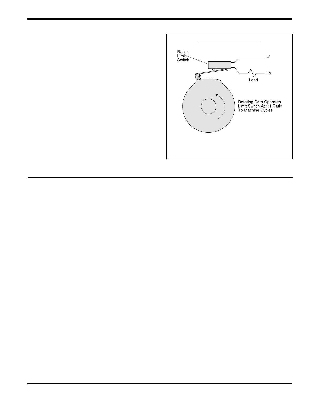
Basic Cam Switch Operation
A PLµS control’s main purpose is to operate outputs in a
manner that simulates cam switches. The drawing to the
right illustrates the operation of a cam switch. Its function is
to switch the load on and off at the same rotary positions of
the cam shaft during each revolution of that cam shaft. The
rotating cam shaft is driven by a machine at a 1:1 ratio, so
that the on / off positions of the cam switch always match
specific positions in the machine cycle. However, cam limit
switches have the following disadvantages: unreliable
(wear), hard to adjust (machine must be stopped during
adjustment), and they cannot run at high speeds because
of contact bounce and excessive mechanical wear.
PLµS controls overcome these basic cam switch problems.
They have no moving wear parts, they are easy to adjust
from the keyboard with the machine running or stopped,
and they can operate at speeds up to 3000 RPM. They also
add many capabilities far beyond simple cam switch logic.
Standard Product Features
Basic Cam Switch Operation
The limit switch will turn on and off at
the same cam degree positions every
cam revolution (every machine cycle)
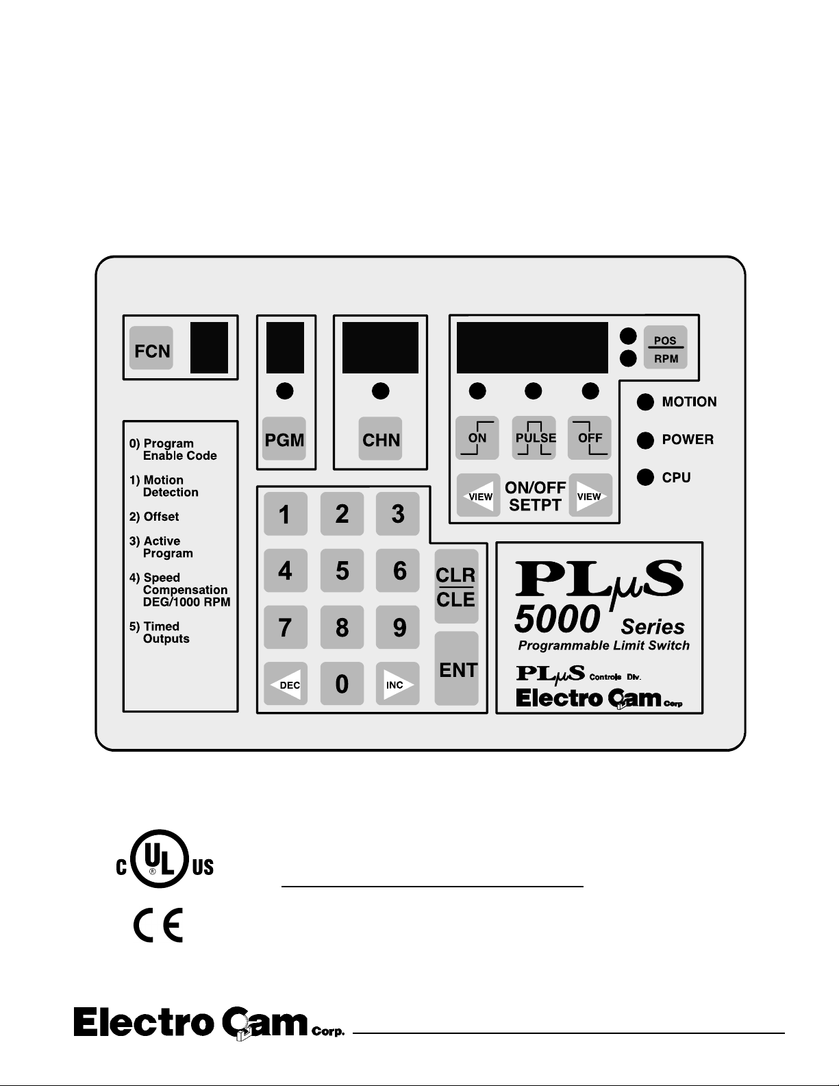
Keyboard/Controller
The keyboard controller is the main component of the PLµS
system. The front keypad and displays provide a complete
user interface from which every aspect of the control’s
operation can be monitored and programmed. When
properly mounted with the gasket provided, the keyboard
meets NEMA 4 standards. A clear silicon rubber boot
assembly is available to provide NEMA 4X protection for
installations where harsh washdown chemicals are used.
Ease of Setup
All output position setpoint values are simply entered
through the numeric keypad. These setpoints can be
adjusted while the machine is running or stopped by using
the increment, decrement, or numeric keys. The keyboard
is also used to synchronize the control’s position to the
machine, eliminating the need to mechanically adjust the
resolver’s shaft position.
Multiple Programs
Depending on the model ordered, up to 64 different
programs, or “job recipes” can be stored in the control’s
memory. This minimizes down time for job change over
because simply changing program numbers makes all of
the output setting changes required. Program numbers can
be changed by mechanical switches; PLC’s (using the
hardware program select inputs); the keypad; or serial
communication messages.
Output Speed Compensation
Speed compensation allows outputs to compensate for the
response time of the controlled devices by turning on earlier
as machine speeds increase. This eliminates the need to
adjust output settings whenever machine speeds are
changed. Using speed compensation often allows higher
production speeds and eliminates the need for output
adjustments.
Motion ANDing
A speed range can be programmed into the controller, and
outputs can then be ANDed with the speed range so that
they will be disabled unless the machine speed is within the
range. This can be used to turn off outputs if the machine
stops; disable outputs until the machine reaches a minimum
speed; or disable outputs if the machine goes above a
specified maximum speed. A common use for this feature
is disabling outputs to glue valves so the flow of glue turns
off if the machine stops.
Timed Outputs
Outputs can be programmed to turn on at the programmed
“on” position and turn off when the specified time elapses,
rather than staying on until an “off” position is reached. The
result is a constant output duration, regardless of machine
speed. The output will turn off when the “off” position is
reached if it hasn’t already timed out. Timed outputs are
used to drive devices which require a fixed time to perform
a task, regardless of machine speed.
1-1 Introduction
Page 6

Standard Product Features (continued)
Selectable Scale Factor (resolvers only)
The number of increments per revolution (Scale Factor) is
programmed by the user. Standard controls have a
maximum of 1024 increments per revolution and “-H” option
(high resolution) controls have a maximum of 4096
increments per revolution. To make the control operate and
program in degrees, a Scale Factor of 360 is used. In some
applications it is desirable to use a Scale Factor that defines
each increment as a specific distance in engineering units
(ex: 1 inc = .1" of travel).
Output Grouping and Modes of Operation
Outputs can be subdivided into groups and each group
can be associated with an input device. There are five
different modes of operation that can be selected for each
group. For example, some modes allow the group to activate
only when the corresponding input has signaled that product
is present. Glue control is a typical place where outputs
are disabled until product is sensed as being present. For
details, see page A-1.
Optional Product Features
Analog Output, “-A”
Units with this option can output an analog signal that is
linearly proportional to RPM. The analog signal level at
zero RPM can be programmed through the keyboard, as
well as the RPM that corresponds to maximum signal. No
measuring equipment is required for initial setup, and
calibration is not needed. Typical uses are control of glue
pressure as machine speed changes, and speed matching
of other equipment to the machine being controlled.
Outputs Based On Rotation Direction, “-D”
In standard PLµS controllers, outputs will turn ON/OFF
based on resolver position, regardless of which way the
resolver is turning. With the "-D" option, outputs can be
based on resolver rotation direction.
Large Program Memory, “-F”
Depending on the number of outputs ordered, standard
controls can store up to 64 programs consisting of not more
than 1258 output pulses total. Controls with the “-F” option
increase this capacity by storing up to 256 programs
consisting of not more than 4589 output pulses total.
Gray Code Position Output, “-G”
The “-G” option provides eight bits of position information
on the last eight outputs. This “gray code” output can be
connected to a PLC or other electronic control device,
eliminating the need for expensive accessory cards. The
PLC can then make control decisions that do not demand
a fast response, while other PLµS outputs directly control
devices that must operate quickly and consistently.
High Resolution, “-H” (resolvers only)
Controls with this option can divide the resolver shaft
Serial Communication
Serial communication provides an RS-232 and an RS-485
communication port. Using PLµSNET software for IBM
compatible computers, available from Electro Cam Corp.,
the control’s entire program can be saved from the control
to a disk file or loaded from a disk file to the control. The
program can be printed or edited using the computer. It is
also possible to send individual communication commands
to the control, while running, to change settings in the
program. The user must write appropriate software to
communicate at the individual command level.
Expanded Operator Access
This feature gives the operator access to motion detection
settings, offset, active program number, and speed
compensation.
NOTE: Serial Communication and Expanded Operator
Access were "-C" and "-E" options prior to date code
9740.
rotation into as many as 4096 increments. Standard
controls have a maximum of 1024 increments.
Leading/Trailing Edge Speed Comp, “-L”
This option allows the “on” and “off” edges of output pulses
to be speed compensated by different amounts. High speed
gluing is a common application where the “on” and “off”
edges of the output signal have to be compensated by
different amounts.
Phase Mark Registration, “-P”
Phase mark registration allows the PLµS control to
determine if a product appears before or after a
programmed timing window. If mis-registration occurs, the
product’s timing can be adjusted manually, or by a PLC or
similar controller interfaced to the PLuS control.
Caustic Washdown Boot, “-W”
The face of the keyboard is rated NEMA 4X (meets NEMA
1, 4, 4X, and 12). For additional protection against caustic
washdown, grease, oil, dirt, and normal wear, a clear
silicone rubber boot is available that fits over and around
the keyboard. The back of the boot provides a good seal
between the back of the keyboard and the control panel.
The boot is transparent and pliable, allowing the keyboard
to be viewed and operated through it. Controls ordered
with the “-W” option are shipped with the boot fitted over
the keyboard. Boots may also be ordered separately and
installed in the field (#PS-4904-99-001).
Remote Display
A remote display which connects to the RS-485 port is
available for units ordered with both the “-C” and “-E”
options. This allows position and RPM information to be
displayed up to 1000 feet away from the controller.
1-2 Introduction
Page 7
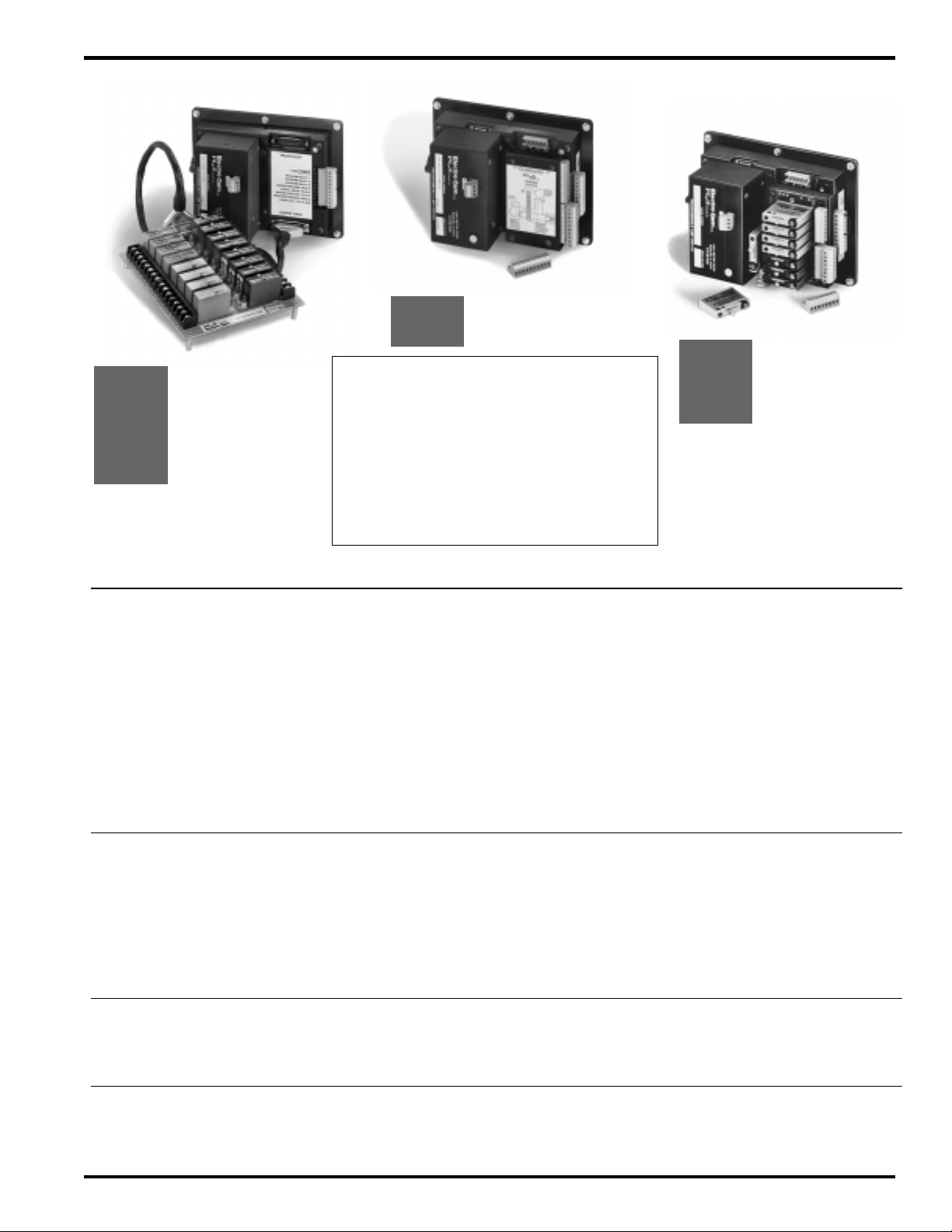
PS-5000 Series Model Summary
PS-5011
PS-5111
Key To Option Selection
PS-5001
PS-5101
PS-5004
PS-5104
PS-5034
PS-5134
Model Output Type Transducer Outputs Programs Modes? Options
PS-5001-10-016 Module Rack Encoder 16 64 no A, F, G, L, P, V, W, 20, 24
PS-5101-10-016 Module Rack Resolver 16 64 no A, F, G, H, L, P, V, W, 20, 24
PS-5001-10-024 Module Rack Encoder 24 48 no F, G, L, V, W, 20, 24
PS-5101-10-024 Module Rack Resolver 24 48 no F, G, H, L, V, W, 20, 24
PS-5001-10-048 Module Rack Encoder 48 24 no F, G, L, V, W, 20, 24
PS-5101-10-048 Module Rack Resolver 48 24 no F, G, H, L, V, W, 20, 24
PS-5004-10-016 Module Rack Encoder 16 64 yes A, F, G, L, P, V, W, 20, 24
PS-5104-10-016 Module Rack Resolver 16 64 yes A, F, G, H, L, P, V, W, 20, 24
PS-5004-10-024 Module Rack Encoder 24 48 yes F, G, L, V, W, 20, 24
PS-5104-10-024 Module Rack Resolver 24 48 yes F, G, H, L, V, W, 20, 24
PS-5004-10-048 Module Rack Encoder 48 24 yes F, G, L, V, W, 20, 24
PS-5104-10-048 Module Rack Resolver 48 24 yes F, G, H, L, V, W, 20, 24
These Models
Use External
I/O Module Racks
20-240 VAC: Change “-10-” to “-20-”.
24-24 VDC: Change “-10-” to “-24-”.
A Analog output proportional to speed
F Additional setpoint/program storage
G Gray code position output
H High resolution, resolver only
L Individual leading/trailing edge speed compensation
P Register mark phasing
U CE mark - requires 24VDC input
V Vibration protective coating
W Washdown Boot
These Models
Use Built-In
I/O Transistor Chips
# of # of Output
PS-5021
PS-5121
PS-5024
PS-5124
These Models
Have I/O Modules
On Controller Back
PS-5011-10-N08 Transistor, Sinking Encoder 8 64 no F, L, V, W, 20, 24
PS-5111-10-N08 Transistor, Sinking Resolver 8 64 no F, H, L, V, W, 20, 24
PS-5011-10-N16 Transistor, Sinking Encoder 16 64 no F, G, L, P, V, W, 20, 24
PS-5111-10-N16 Transistor, Sinking Resolver 16 64 no F, G, H, L, P, V, W, 20, 24
PS-5011-10-P08 Transistor, Sourcing Encoder 8 64 no F, L, V, W, 20, 24
PS-5111-10-P08 Transistor, Sourcing Resolver 8 64 no F, H, L, V, W, 20, 24
PS-5011-10-P16 Transistor, Sourcing Encoder 16 64 no F, G, L, P, V, W, 20, 24
PS-5111-10-P16 Transistor, Sourcing Resolver 16 64 no F, G, H, L, P, V, W, 20, 24
PS-5034-10-032 Transistor, Ext. Rack Encoder 32 32 yes F, G, L, V, W, 20, 24
PS-5134-10-032 Transistor, Ext. Rack Resolver 32 32 yes F, G, H, L, U, V, W, 24
PS-5034-10-064 Transistor, Ext. Rack Encoder 64 16 yes F, G, L, V, W, 20, 24
PS-5134-10-064 Transistor, Ext. Rack Resolver 64 16 yes F, G, H, L, U, V, W, 24
PS-5021-10-M09 Modules on Back Encoder 9 64 no A, F, L, V, W, 20, 24
PS-5121-10-M09 Modules on Back Resolver 9 64 no A, F, H, L, P, U, V, W, 20, 24
PS-5024-10-M09 Modules on Back Encoder 9 64 yes A, F, L, V, W, 20, 24
PS-5124-10-M09 Modules on Back Resolver 9 64 yes A, F, H, L, P, U, V, W, 20, 24
1-3 Introduction
Page 8
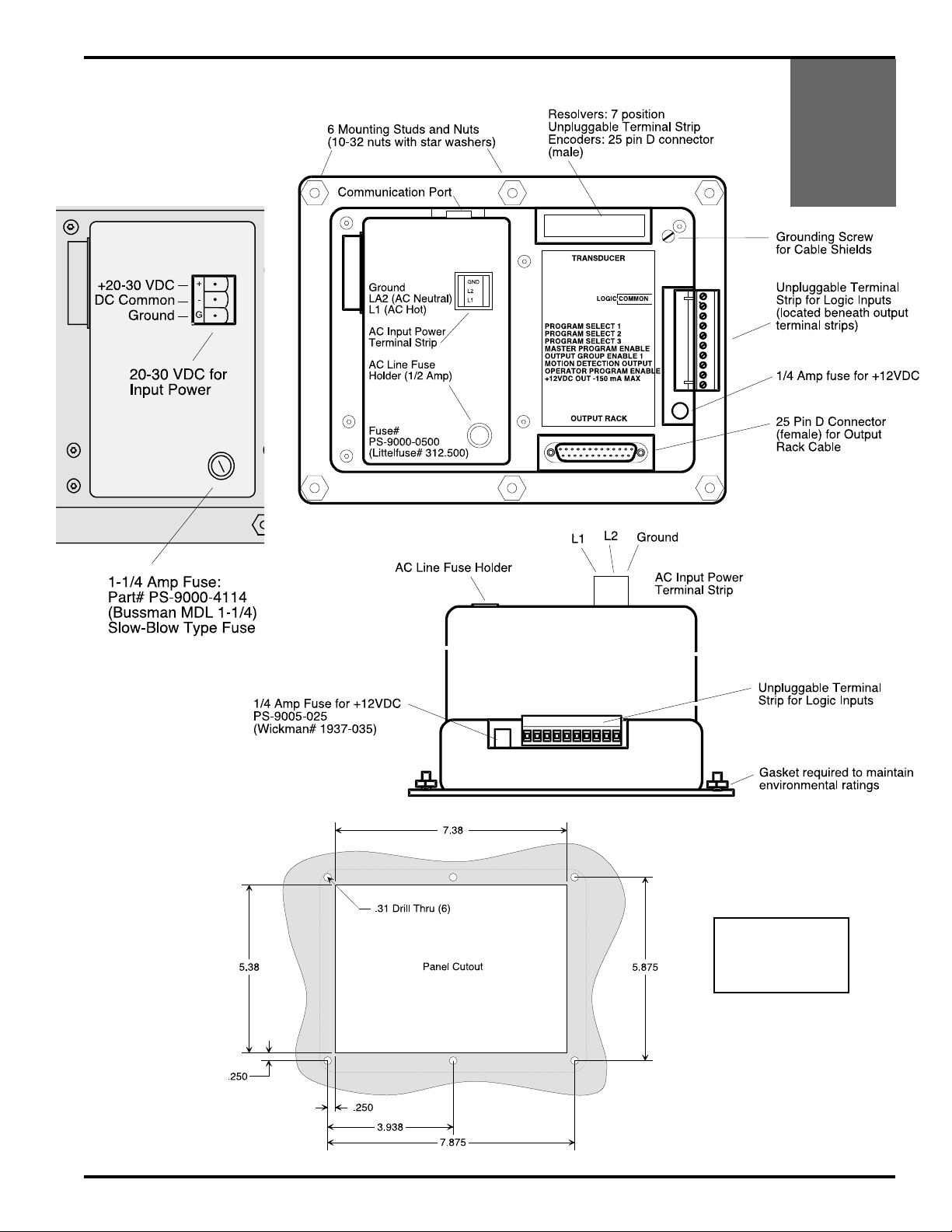
Detailed View of
24 VDC Version
Controllers w/ External I/O Module Rack
PS-5001
PS-5101
PS-5004
PS-5104
PS-5034
PS-5134
2-1 Dimensions & Component Locations
See Page 2-4
for Controller
Dimensions
Page 9
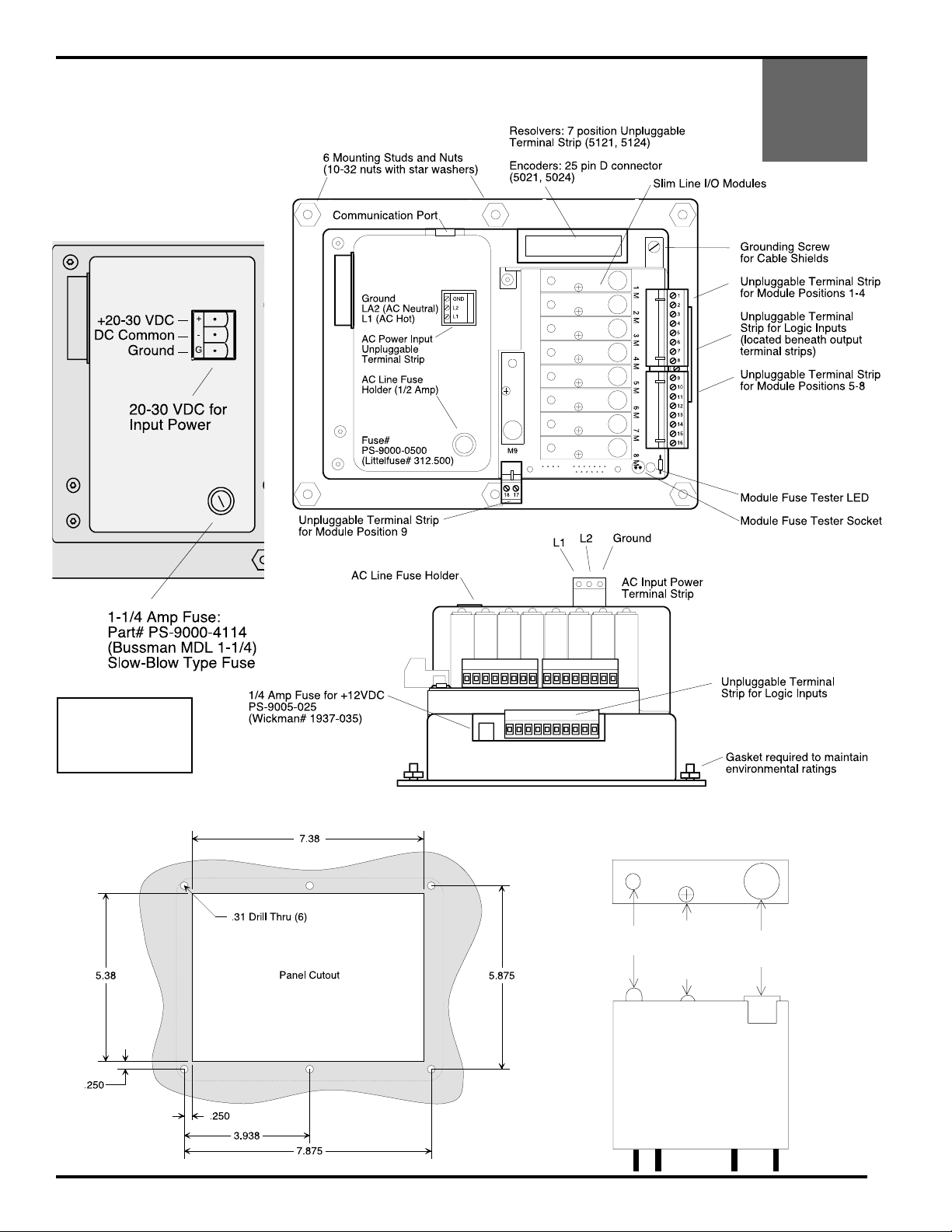
Controllers w/ I/O Modules on Controller Back
LED
HOLD
DOWN
SCREW
FUSE
4A
Detailed View of
24 VDC Version
PS-5021
PS-5121
PS-5024
PS-5124
See Page 2-4
for Controller
Dimensions
Slimline Modules
TOP
2-2 Dimensions & Component Locations
Page 10
Detailed View of
24 VDC Version
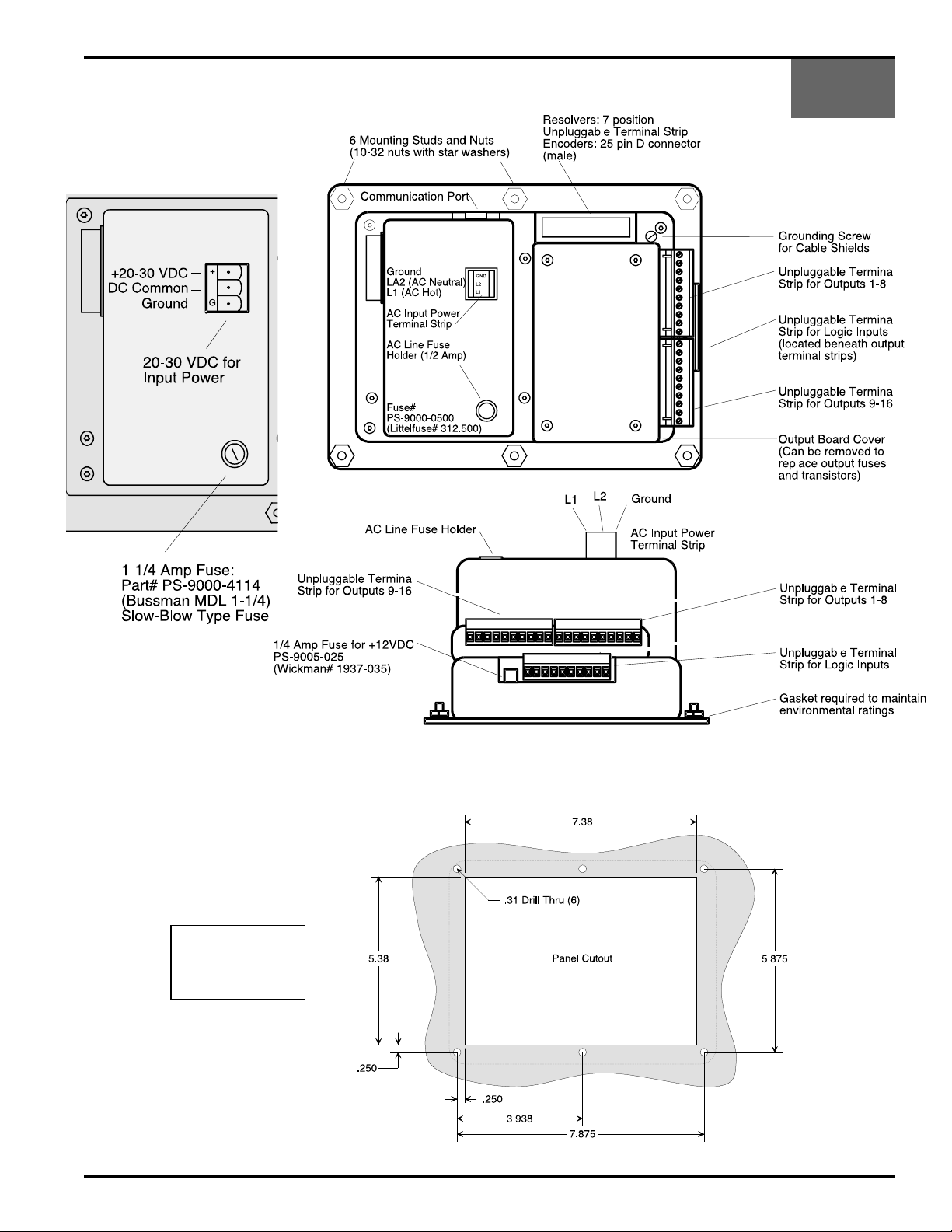
Controllers with Built-In Transistor I/O Chips
PS-5011
PS-5111
See page 2-5
for Controller
Dimensions
2-3 Dimensions & Component Locations
Page 11
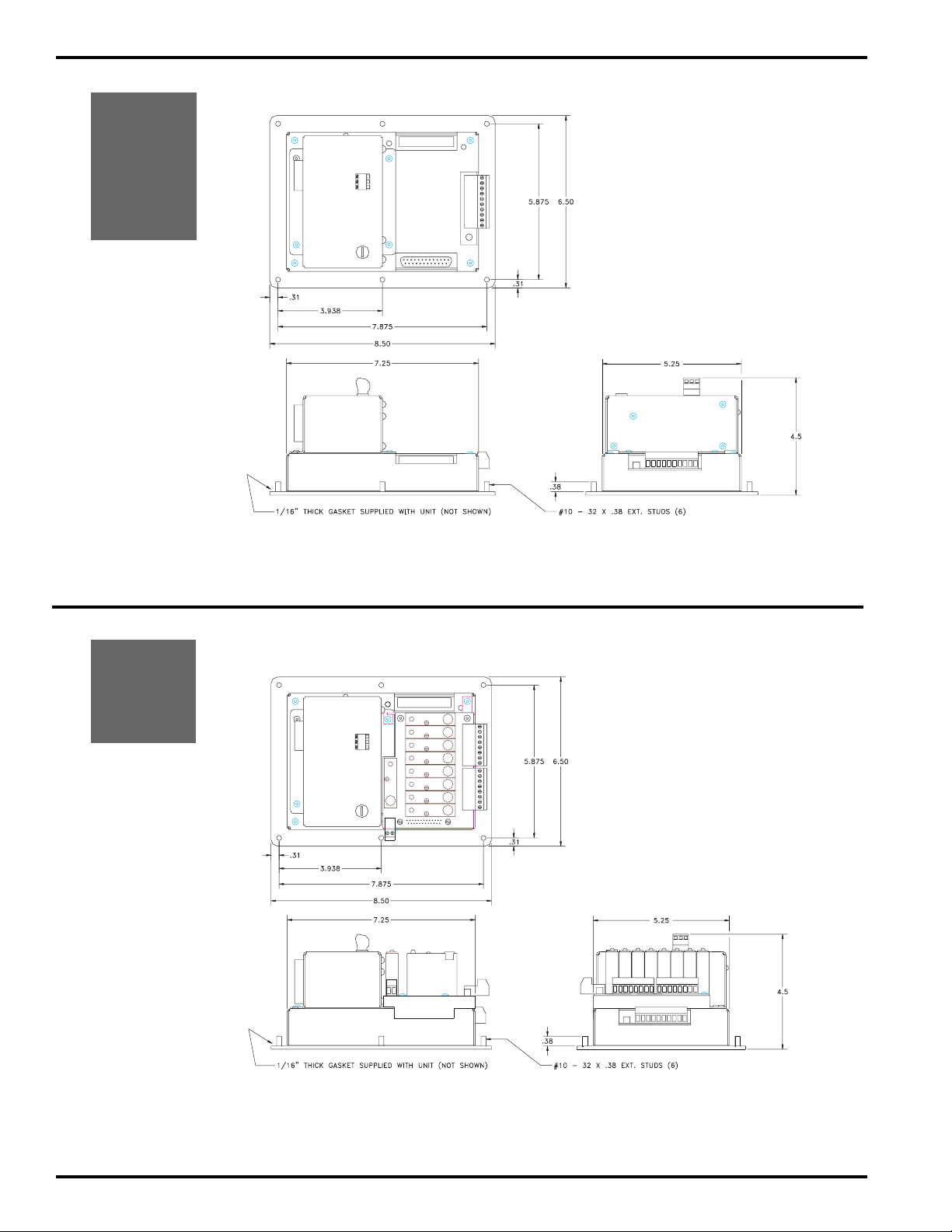
PS-5001
PS-5101
PS-5004
PS-5104
PS-5034
PS-5134
Controller Dimensions
PS-5021
PS-5121
PS-5024
PS-5124
2-4 Dimensions & Component Locations
Page 12
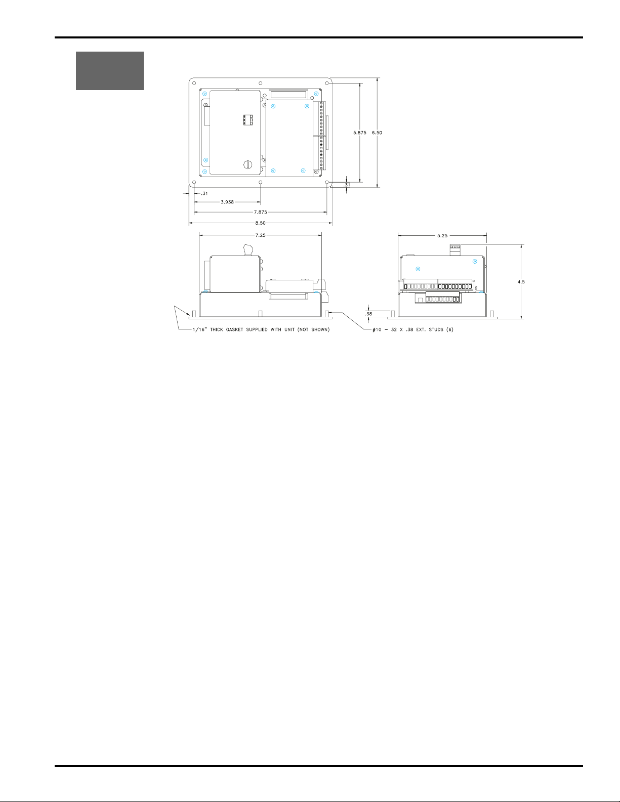
PS-5011
PS-5111
Controller Dimensions
2-5 Dimensions & Component Locations
Page 13
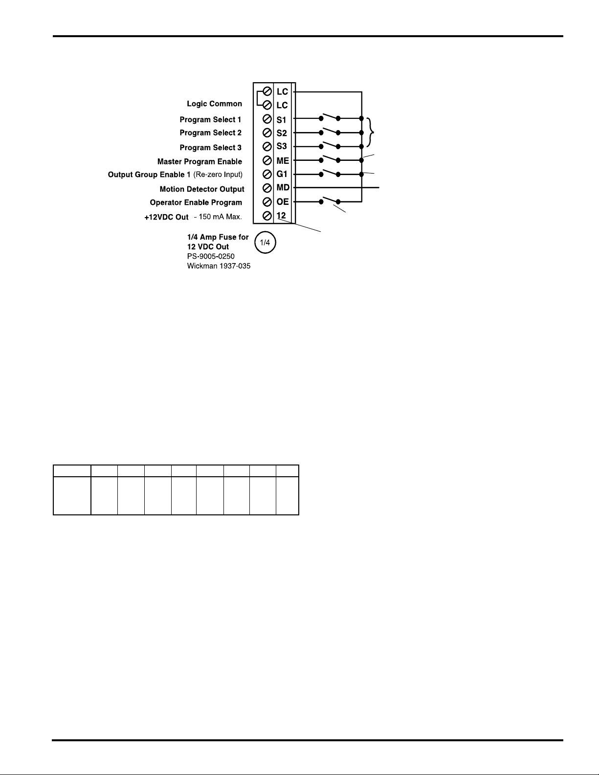
Logic Terminal Strip Wiring—Standard Controller
Logic Terminal Strip
(see pp. 2-1 thru 2-3 for location)
General Logic Input Information
The logic inputs, Terminals 2-7 & 9, are switched by a
current sinking path to Logic Common. They can be switched
by mechanical switches, relays, or NPN transistor outputs.
Logic input terminal voltage is approximately 12 VDC, and
4 mA of current are conducted through the switch to Logic
Common.
Program Select Inputs (Terminals 3, 4, and 5)
These inputs determine which program in the current
program bank is controlling the outputs. When any of these
inputs are connected to Logic Common, they take priority
over the keyboard selected active program (FCN 3). If these
inputs are being used, make sure that the FCN 3 active
program is set to 1. Input combinations are:
PRG # 1 2 3 4 5 6 7 8
SEL 1 off on on off off on on off
SEL 2 off off o n on on on off off
SEL 3 off off off off on on on on
Master Program Enable (Terminal 6)
When the Master Program Enable input is switched to Logic
Common, all programming operations are accessible. A
key switch is commonly used for this input to prevent
unauthorized personnel from accessing the more
complicated features of the control. A temporary jumper can
also be installed for initial programming at the master level,
and then removed when this programming is completed.
Output Group 1 Enable (Re-Zero Input) (Terminal 7)
On standard 5XX1 controls, switching this input to Logic
Common instantly changes the control's position to zero
degrees. The position re-zeroes off of the leading edge of
the signal, but is not held at zero while the input is energized.
When the controller is de-energized, the controller position
will revert to the offset value programmed in FCN 2.
Program Select Switch and Cable:
Pt# PS-4901-01-XXX (XXX=FT)
Program Enable key switch and cable:
PS-4902-01-XXX (XXX=FT)
Input from photo sensor typically
To PLC or other electronic input
Program Enable key switch and cable:
PS-4902-01-XXX (XXX=FT)
DC power for accessories, typically photo sensors.
Terminals 1 and 2 are negative side of this supply
On models PS-5004, 5104, 5024, and 5124 this input is the
enable input for output Group 1. There are four programmable
modes of operation available for enable inputs. For more
information see the Output Grouping and Enable Modes
section in the Appendix.
Motion Detection Output (Terminal 8)
This is a sourcing output signal that is on whenever the
current machine speed is within or equal to the Low and
High RPM setpoints (FCN 1, page 4-7). The circuit is
basically a 12 VDC supply being sourced through a 470
ohm resistor. It is typically connected to PLC inputs or
external solid state output modules. Because the 5000
Series controls have Motion ANDing, any of the standard
outputs can be programmed to be on whenever the motion
logic is on. This is an alternative to the Motion Output when
it is not compatible with an input circuit or if a higher voltage
or current needs to be controlled.
Operator Program Enable (Terminal 9)
When this terminal is switched to Logic Common, access to
programming at the Operator level is enabled. A key switch
can be used to control who can make program changes at
the Operator level. Operator access can also be enabled
through a keyboard enable code number.
12 VDC Power Output (Terminal 10)
The 12 VDC accessory power supply is regulated and
capable of supplying up to 150 mA. It is protected by a 1/4
amp fuse which is located just below the Logic Terminal
strip. This supply is intended to be used for electronic
sensors or other electronic circuitry. It should not be used to
power relays or any other inductive devices. Logic Common
(terminals 1 or 2) is the negative side of this 12 VDC supply.
3-1 Wiring
Page 14
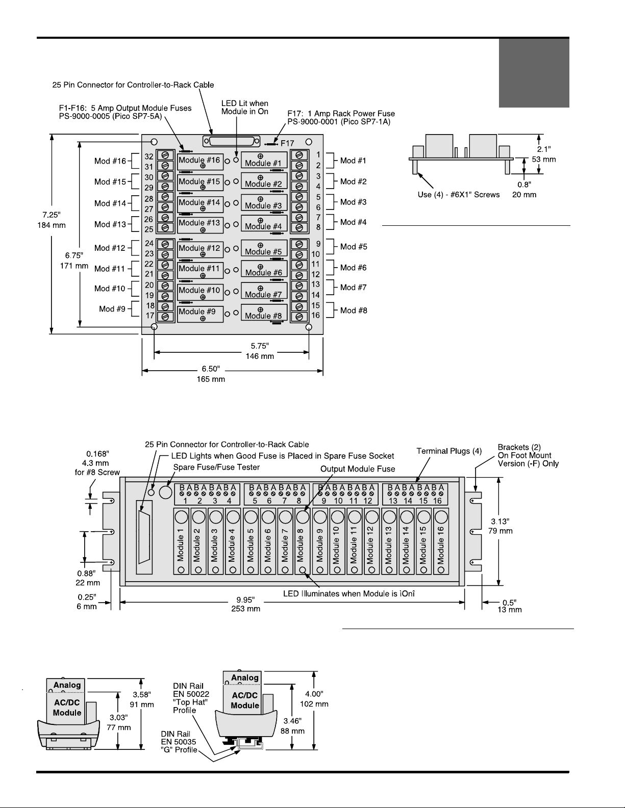
External 16 Module I/O Racks: Dimensions & Specifications
Standard 16 Rack: PS-4100-11-216
Analog 16 Rack: PS-4100-11-316-A (for “-A” Option Only)
PS-5001
PS-5101
PS-5004
PS-5104
End View
Notes:
•A Standard module is required for each Input or
Output used. See Appendix for module specs.
• AC and DC modules can be mixed as needed.
• Input modules can be used only with 5004 and 5104
units.
• Output modules act like switches; they do not
supply power to loads.
• Position 16 of Analog racks is dedicated to analog
output and will not work with other modules. If an
analog module is used, it must be installed in
position 16.
• Odd Terminals: (+) or hot
Even Terminals: (-) or load
Slimline M16 Rack
Foot Mount Rack: PS-4100-11-M16-F
DIN Rail Rack: PS-4100-11-M16-D
End Views
Foot Mount (-F)
DIN Rail (-D)
Notes:
•A Slimline module is required for each Input or Output used.
See Appendix for module specs.
• AC and DC modules can be mixed as needed.
• Input modules can be used only with 5004 and 5104 units.
• Output modules act like switches; they do not supply
power to loads.
• Analog modules may be installed in position 16 only.
• Module Fuses: 4 Amp, #PS-9005-0004
(Wickman 19370-K)
• “A” Terminals: (-) or load
“B” Terminals: (+)or hot
3-2 Wiring
Page 15
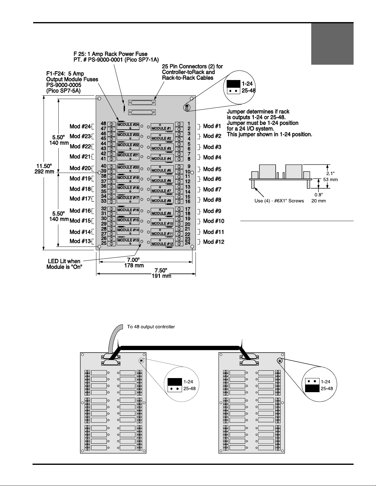
External 24 & 48 Module I/O Racks: Dimensions & Specifications
Standard 24 Rack: PS-4100-12-224
PS-5001
PS-5101
PS-5004
PS-5104
End View
Configuration for 48 I/O System
Notes:
•A Standard module is required for each Input or
Output used. See Appendix for module specs.
• AC and DC modules can be mixed as needed.
• Input modules can be used only with 5004 and 5104
units.
• Output modules act like switches; they do not
supply power to loads.
• Either 25 pin connector can be used to connect the
rack to the controller. The other connector ties to a
second rack for 48 I/O as shown below.
• Odd Terminals: (+) or hot
Even Terminals: (-) or load
3-3 Wiring
Page 16
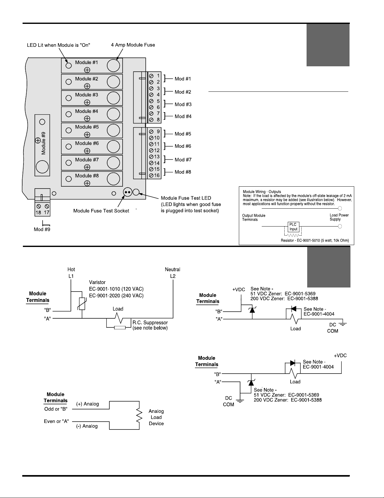
Slimline I/O Modules on Controller Back: Specifications
Back View of Controller Body
PS-5021
PS-5121
PS-5024
PS-5124
Notes:
• A module is required for each Input or Output used. See
Appendix for module specs.
• AC and DC modules can be mixed as needed.
• Input modules can be used only with 5024 and 5124 units.
• Output modules act like switches; they do not supply power
to loads.
• Analog modules may be installed in Position 9 only, and
only on units ordered with option “-A”.
• Module Fuses: 4 Amp, #PS-9005-0004 (Wickman 19370-K)
• Odd Terminals: (+) or hot
Even Terminals: (-) or load
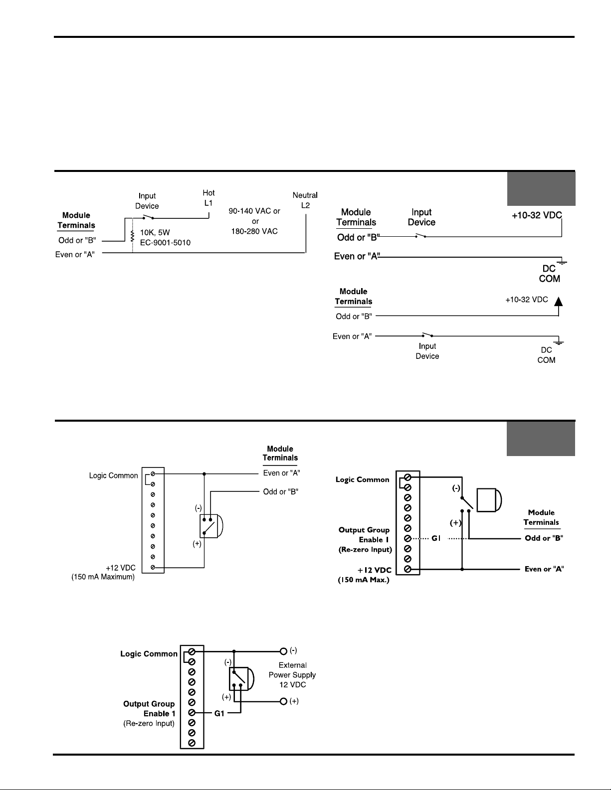
Module Wiring - Outputs
AC Output
Odd or
Even or
• Most applications will not need the varistor or R-C suppressor shown
above. However, when other switching devices are in series or parallel
with the AC module, voltage spikes may damage the module. Use one
of the following two methods to suppress voltage spikes.
• For infrequent switching, connect a varistor (MOV) across the terminals.
• For continuous switching, wire an R-C suppressor in parallel with the
load.
Analog Output
• Control must have Option “-A” to use analog output module.
• Analog output modules source the analog signal.
• Analog output signals are isolated.
• Caution: Do not apply external voltage to an analog module or you will
damage it.
DC Output
Sourcing
PS-5X04
PS-5X21
PS-5X24
Odd or
Even or
Sinking
Odd or
Even or
• Most applications will not need the diodes shown above. However,
highly inductive DC loads may damage modules by generating voltage
spikes when switched off. Suppress these loads using one of these two
methods:
• Connect a Zener diode across the terminals. This will not significantly
increase the load turn off time. Voltage rating of the diode must be
greater than the normal circuit voltage.
• Connect a reverse-biased diode across the load. This may increase the
load turn off time.
PS-5X01
3-4 Wiring
Page 17
Sinking or Sourcing (as pertaining to Electro Cam Corp. products)
Sinking means that when the logic is true and the output (or input device) is ON, the output (or input device)
is providing a DC common or ground to the connected device.
Sourcing means that when the logic is true and the output (or input device) is ON, the output (or input device)
is providing a +DC voltage to the connected device.
This information is important when interfacing an Electro Cam Corp. product with another electronic device. If you are using an Electro Cam Corp. product
input to an Allen-Bradley 1746-IN16 “sinking” input card* or similar A-B device, you have to supply a +DC voltage (Electro Cam Corp.
to this card, NOT a DC common or ground. In these cases,
*Other manufacturers include, but not limited to: Koyo (formerly GE Series 1, Texas Instruments, or Siemens SIMATIC PLS’s) that use descriptions
similar to Allen-Bradley.
Sinking
is what the card does with the input voltage; sinks it to common or ground.
Sourcing
output)
Module Wiring—Inputs
AC Input
• Input devices can be mechanical contacts or solid state.
• The load 10K load resistor shown may be needed if the AC input device
has off-state leakage, such as a solid state triac.
Input Wiring, 3-Wire Sensors
Using Logic Terminal Strip Power Supply (pg. 3-1)
Sourcing
DC Input
Sourcing
PS-5024
PS-5124
Sinking
• Input devices can be mechanical contacts or solid state.
• 12 VDC power is available from the controller’s logic terminal strip. See
page 3-1 for details.
Various
Sinking
Models
• For controllers using input/output modules.
Using External Power Supply & Terminal 7
• Module wiring applies only to controllers using input/output modules.
• Using sensor to switch terminal 7 can be done for any PS-5000 Series
controller. See page 3-1 for details.
• Using sensor to switch terminal 7 can be done for any PS-5000 Series
controller. See page 3-1 for details.
3-5 Wiring
Page 18
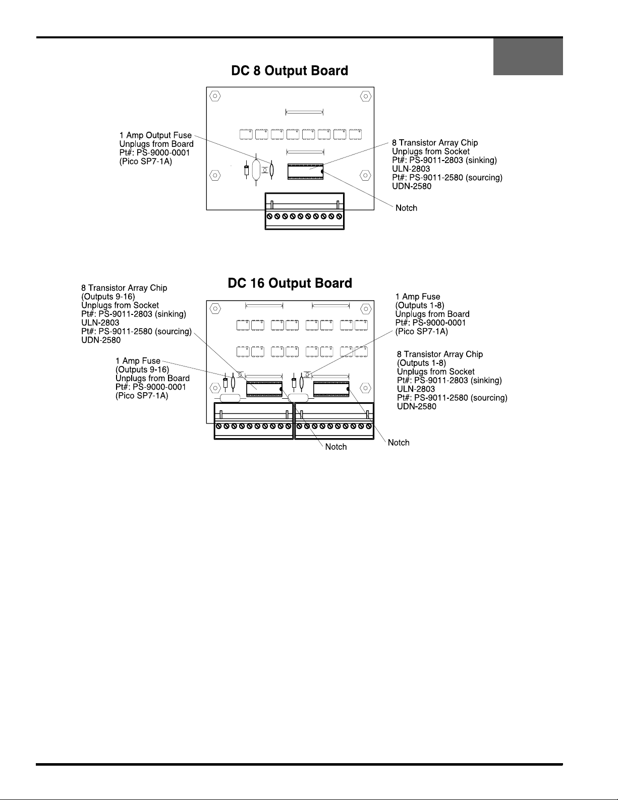
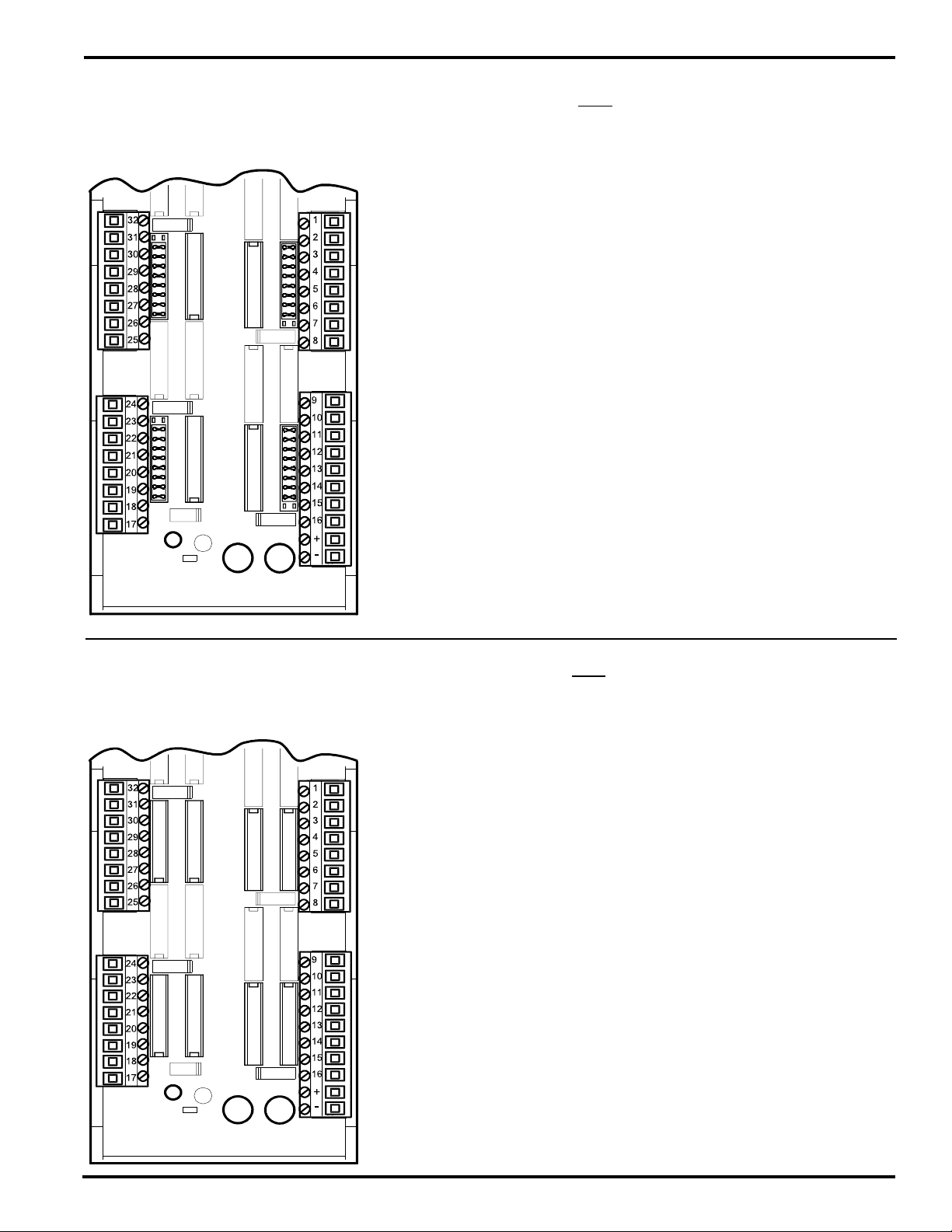
Built-In Transistor I/O Chips: Specifications
PS-5011
PS-5111
The output board which contains the output transistor array
chips and the fuse(s) is located under the output board
cover. The pluggable output terminal strips plug into receptacles that are mounted to the output board The only time
it will be necessary to remove the output board cover is
when an output fuse is blown or a transistor array chip is
damaged.
Output Transistor Array Chips:
Each group of 8 output transistors is contained in a single 18
pin transistor array chip. If one or more of these transistors
becomes damaged, the chip can simply be unplugged from
the socket and replaced. Note that Sinking and Sourcing
output boards do not use the same transistor array chip.
Output Fuses:
Each group of 8 outputs (1 transistor array chip) is protected
by a 1 Amp plug in fuse. This fuse will blow if the DC power
polarity is incorrectly wired to the “+” and “-” terminals on the
output terminal strip. On the sourcing output versions this
fuse will also blow if the total amount of current being
3-6 Wiring
conducted by that group of 8 outputs exceeds 1 Amp. If a
fuse blows, all 8 of the outputs in that group will be inoperative until the fuse is replaced.
Output Cables:
Pluggable screw terminal strips are used to connect the
transistor outputs to the load device. Therefore, no special
connectors are needed for output wiring. However, shielded
cable is recommended (Electro Cam part #: PS-4300-04XXX, 2 cables required for systems with more than 8
outputs) to maximize immunity to electrical noise. The
shield should be connected to the grounding screw located
on the back panel just above the output terminal strips. The
shield should be unconnected at the load end of the cable.
Also, the cable should be kept away from other electrical
wiring, especially control wiring involving solenoids, relays,
contactors, and motors.
Page 19
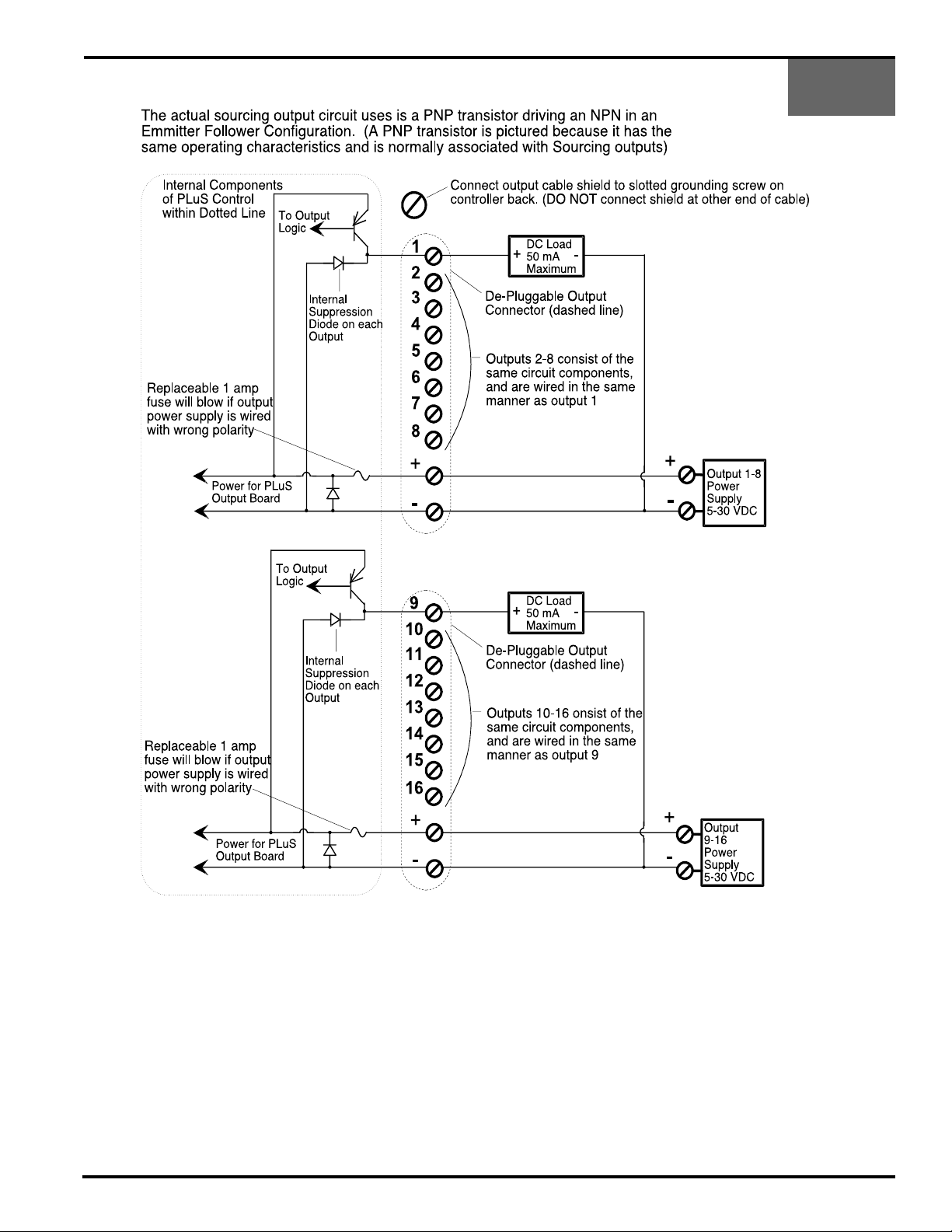
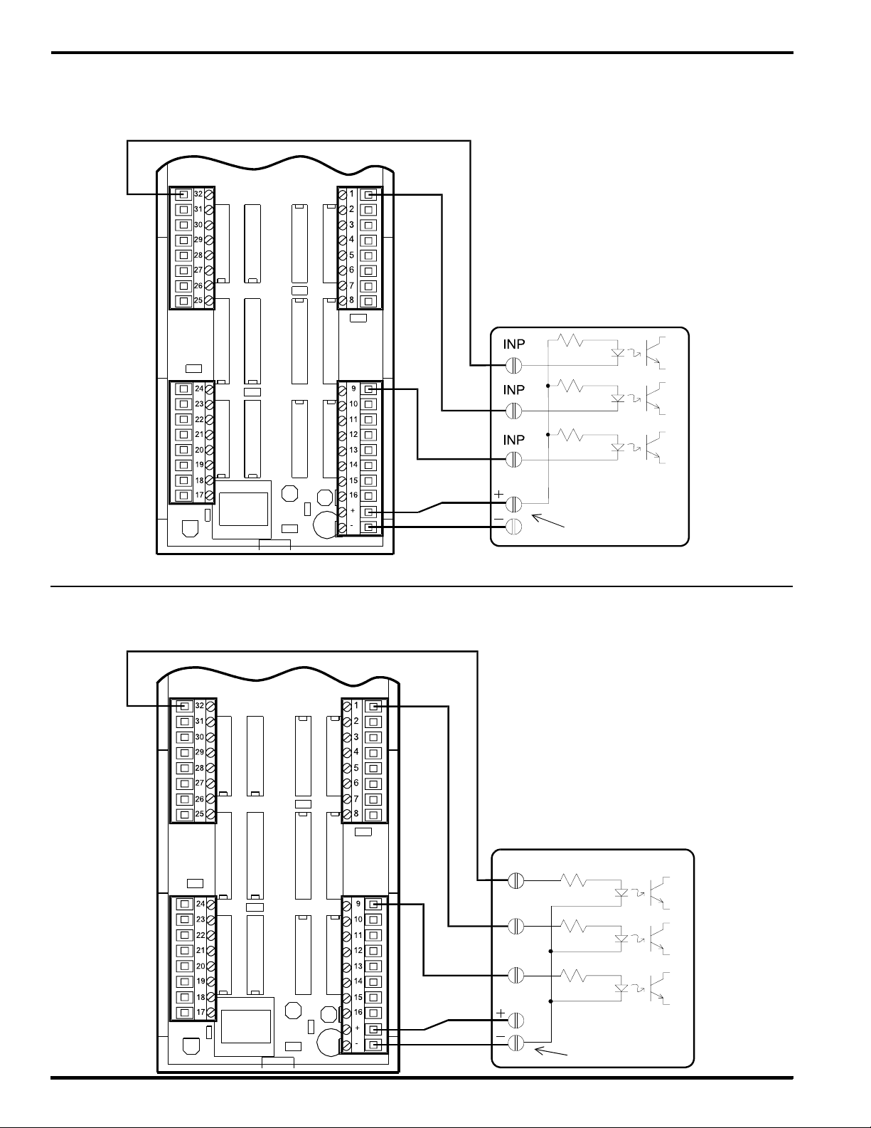
Built-In Transistor I/O Chips: Output Wiring, Sourcing
PS-5011
PS-5111
The output power supplies shown can be internal to the
load device being driven. This will normally be the case
when connecting to PLC's.
The loads connected to outputs 1-8 must all be powered
from the same power supply.
The loads connected to outputs 9-16 must all be powered
from the same power supply.
The same power supply can be used to power all 16 outputs
by paralleling the wiring between the “+” and “-” terminals
on the PLµS output terminal strips.
3-7 Wiring
The load power supply must be connected to both the “+”
and “-” terminals on the output terminal strip(s).
The unpluggable output terminal strips are keyed so they
can only be plugged into the correct receptacle.
Use shielded cable(s) for output wiring. Electro Cam 10
conductor cable part number PS-4300-04-XXX (XXX=length
in feet) is recommended. Two cables required for 16 output
units.
Page 20
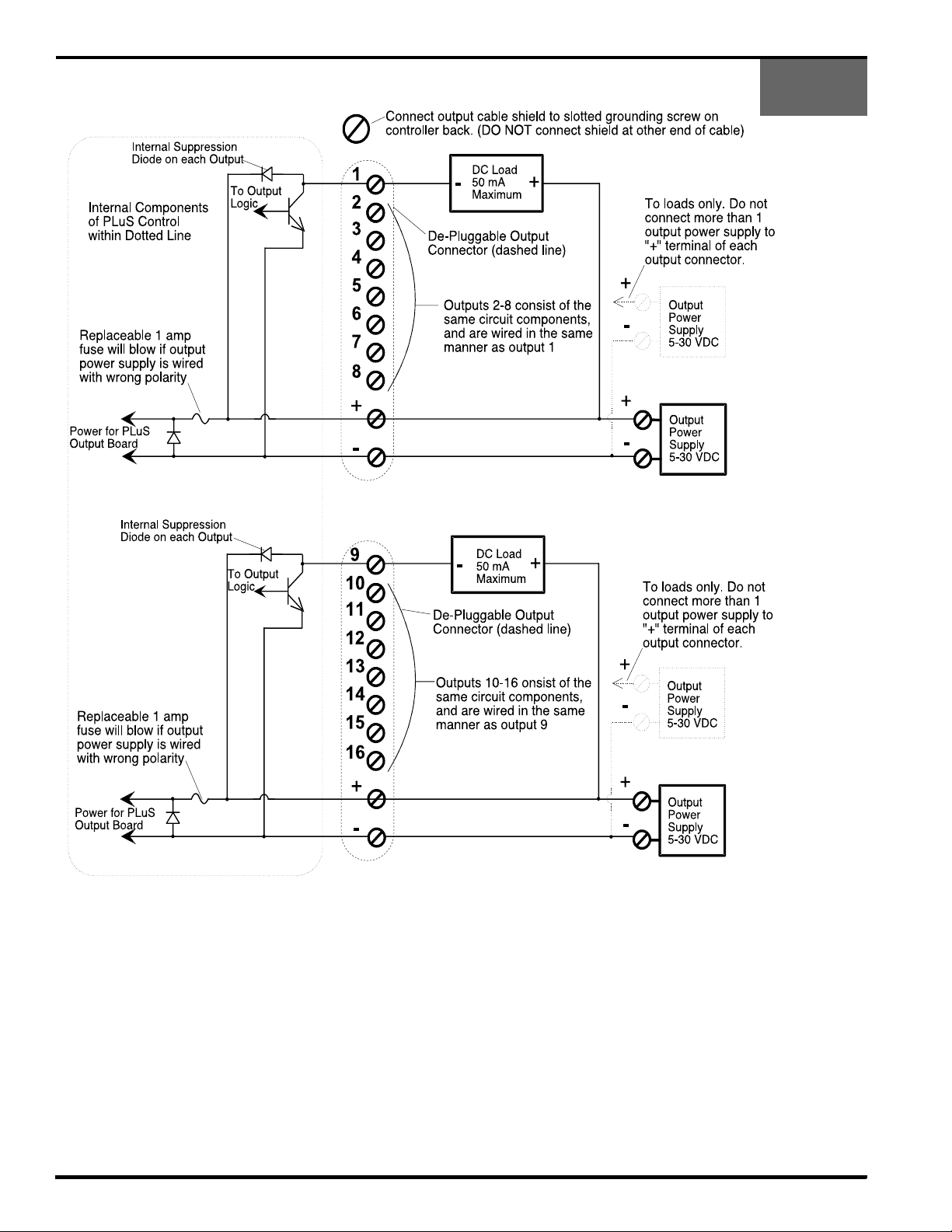
Built-In Transistor I/O Chips: Output Wiring, Sinking
PS-5011
PS-5111
The output power supplies shown can be internal to the load
device being driven. This will normally be the case when
connecting to PLC's.
More than 1 power supply can be used to power loads within
each group of 8 outputs. Only one of the power supplies
used within the group can have its positive side connected
to the “+” terminal of the corresponding 5011 output terminal
strip. The common of each power supply used within a
group of 8 outputs must be connected to the “-” terminal of
the output terminal strip.
3-8 Wiring
The same power supply can be used to power all 16 outputs
by paralleling the wiring between the “+” and “-” terminals on
the 5011 output terminal strips.
Both the “+” and “-” terminals on the output terminal strip(s)
must be connected to a load power supply.
The unpluggable output terminal strips are keyed so they
can only be plugged into the correct receptacle. Do not force
when plugging them in.
Use shielded cable(s) for output wiring. Electro Cam 10
conductor cable part# PS-4300-XXX (XXX=length in feet) is
recommended. Two cables required for 16 output units.
Page 21

Built-In Transistor I/O Chips: Output Wiring to PLC
PS-5011
PS-5111
PS-5X11 with
Sinking Outputs
PLC with Sinking Inputs
(A.B. calls these sourcing inputs)
Power Supply can be
external from the PLC.
PS-5X11 with
Sourcing Outputs
PLC with Sourcing Inputs
(A.B. calls these sinking inputs)
Power Supply can be
external from the PLC.
3-9 Wiring
Page 22
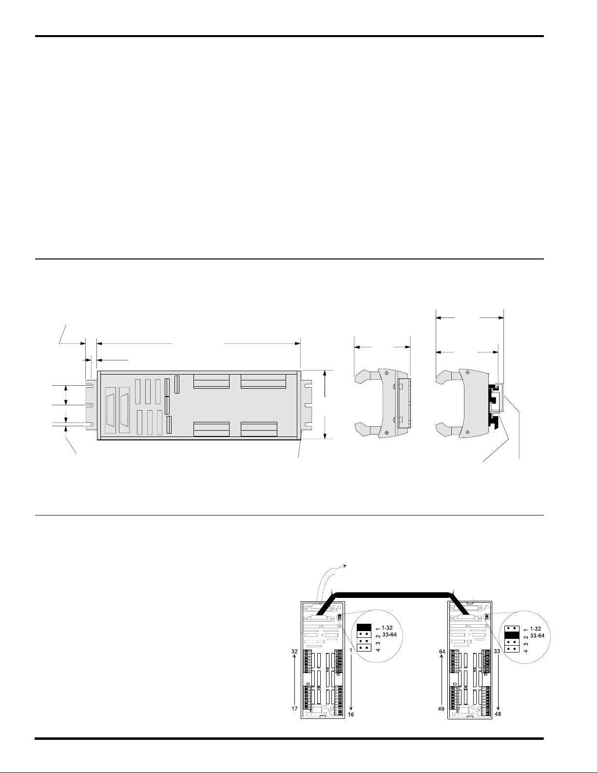
PS-5X34 Controller & 32 DC Output Rack
Introduction
The PS-5X34 system is available with either 32 or 64 low
current transistor outputs. These systems are intended to
be interfaced directly to PLCs or other control devices with
low level DC inputs.
The 32 transistor output rack(s) used with PS-5X34 controls
can be DIN rail mounted (-D) or foot mounted (-F) and are
available with Sinking or Sourcing outputs.
Systems that require 32 or fewer outputs will only need one
of the transistor output racks. Systems requiring more than
32 outputs need two transistor output racks daisy chained
together (see rack configuration section below).
PS-4100-12-X32-X Dimensioned Drawing
1/2" (13mm)
9"
(229mm)
7/8"
(22mm)
1/4" (6mm)
The PS-5X34 controller incorporates the same keyboard
and features that other PS-5000 controls use. Because of
the large number of outputs being controlled, the number of
programs stored in a 32 output controller is 32, and the
number of programs in a 64 output controller is 16.
This control has PS-5XX4 capabilities (output grouping and
modes) and includes an RS-232/485 communications port.
Outputs can be subdivided into as many as 8 groups, and
the position of each of these groups can be offset individually.
Because the rack transistor outputs cannot be configured
as inputs, the only enable input available is the "Output
Group Enable 1" input located on the logic strip. Output
Group 1 can operate in any output mode, all other groups
must operate in Mode 0 only.
DIN Rail Mount*
Foot Mount
2-1/2"
(64mm)
3"
(76mm)
2-13/16"
(72mm)
C
L
0.168" (4.3mm)
For #8 Screw
*DIN Rails must be ordered separately
Brackets (2) on
Foot Mount Version (-F) Only
Output Rack Configuration
Control systems requiring 32 or fewer outputs will need only
1 PS-4100-12-X32 transistor output rack. The "Rack
Address Jumper" must be plugged into position 1. This will
configure the outputs to be channels 1-32. 1 rack cable (Pt#
PS-4300-02-XXX) will be needed to connect the rack to the
controller.
Control systems requiring more than 32 outputs will need 2
PS-4100-12-X32 transistor output racks. The "Rack Address
Jumpers" must be plugged into position 1 on one of the
racks, and position 2 on the other. Output channel numbers
will be assigned as shown in the illustration to the right. 2
rack cables (Pt# PS-4300-02-XXX) will be needed: one to
connect the controller to the first rack and the other to
connect the two racks.
3-1/8"
(79mm)
DIN Rail
EN 50022
To PS-5X34 Control
DIN Rail
EN 50035
3-10 Wiring
Page 23
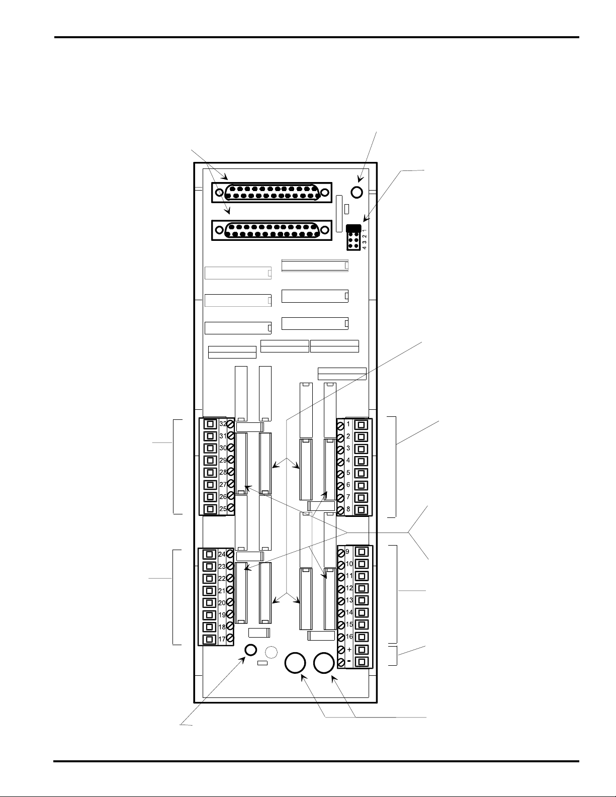
PS-5X34 System: Output Rack Layout
Sinking Output Rack Pt#: PS-4100-12-N32 Sourcing Output Rack Pt#: PS-4100-12-P32
Each Output can Source 10-30 VDC, 100 mA MaxEach Output can Sink 3-30 VDC, 100 mA Max
DB 25 Connectors (Female)
Connect to PLuS controller or another rack
(these connectors can be used interchangeably)
Output Terminals
25-32
E.C. Pt#: PS-9006-0014
(unpluggable)
PLµS Power LED
On when PLµS control is powered up
and connected to rack
Rack Address Jumper
1: Channels 1-32
2: Channels 33-64
3: Unused
4: Unused
(Jumper shown in position 1)
Transistor Array Chips
(socketed for field replacement)
X
E.C. Pt#: PS-9011-2803
Generic Pt#: ULN-2803
Output Terminals 1-8
E.C. Pt#: PS-9006-0011
(unpluggable)
Transistor Array Chips on
Y
X
Y
X
Sourcing Output Racks
(socketed for field replacement)
E.C. Pt#: PS-9011-2580
Generic Pt#: UDN-2580
Output Terminals
17-24
E.C. Pt#: PS-9006-0013
(unpluggable)
F1
X
Y
F2
Y
X
User Power LED
On when user power applied to rack
(will NOT be on if user power fuse is blown)
3-11 Wiring
Y
OR
Dip Jumper Blocks on
Sinking Output Racks
E.C. Pt#: PS-9006-0015
Output Terminals 9-16
E.C. Pt#: PS-9006-0012
(unpluggable)
User DC Power Input
10 - 30 VDC, 4 Amp Max
(Sinking outputs switch "-")
(Sourcing outputs switch "+")
User DC Power Fuses
4 Amps (F1= "+", F2="-")
E.C. Pt#: PS-9005-0004
Wickman Pt#: 19370-K
Page 24
PS-5X34 System: Wiring to PLCs
Wiring to a PLC with Sinking Inputs
(A.B. calls these Sourcing Inputs)
PS-4100-12-N32
Note: PLµS transistor output
rack and PLC MUST
both be connected to
the same DC positive.
PLC
Power Supply can be
external from the PLC
Wiring to a PLC with Sourcing Inputs
PS-4100-12-P32
(A.B. calls these Sinking Inputs)
Note: PLµS transistor output
rack and PLC MUST
both be connected to
the same DC common.
PLC
3-12 Wiring
Power Supply can be
external from the PLC
Page 25
PS-5X34 System: Output Rack Transistor Array Chips
Transistor Array Chip Layout on PS-4100-12-N32 Sinking Output Rack
PS-4100-12-N32
ULN-2813
ULN-2813ULN-2813
ULN-2813
The output circuits of the Sinking and Sourcing output boards are powered
through the "User Power Fuses." If the outputs on these boards are
malfunctioning, check that both fuses are good before investigating
the transistor array chips. If the fuses are good, the "User Power LED"
will be lit. When either fuse is blown, the LED will not light and all 32 outputs
will be dead. Verify that "User DC Power" is present.
The transistor array chips and jumper blocks used on the Sinking board are
socketed for field replacement. In the event of a wiring error or accidental
short circuit, it is possible to damage one or more array chip. In these
situations, replacing the ULN-2813 chip(s) will usually correct the problem.
The orientation of the these chips is critical with respect to their notched
ends. Insure that all chips are oriented in the direction shown in the
illustration to the left.
The jumper blocks installed in the sockets next to the terminal strips do NOT
short together all 9 sets of parallel socket holes - one set is left open. Insure
that the open set of holes is at the correct end of the corresponding socket
as pictured in the illustration to the left. A connection between these two
holes will short out the "User DC Power" supply and cause one of the
"User DC Power Fuses" to blow.
Part Numbers
Sinking Transistor Array Chip: E.C. PT# PS-9011-2803
Generic PT# ULN - 2803
16 Pin Dip Jumper Block: E.C. PT# PS-9006-0015
Transistor Array Chip Layout on PS-4100-12-P32 Sourcing Output Rack
PS-4100-12-P32
ULN-2813 ULN-2813
UDN-2580
ULN-2813
UDN-2580
UDN-2580
The output circuits of the Sinking and Sourcing output boards are powered
through the "User Power Fuses." If the outputs on these boards are
malfunctioning, check that both fuses are good before investigating
the transistor array chips. If the fuses are good, the "User Power LED"
will be lit. When either fuse is blown, the LED will not light and all 32 outputs
will be dead. Verify that "User DC Power" is present.
Two types or transistor array chips are used on the Sourcing board. They
are all socketed for field replacement. In the event of a wiring error or
accidental short circuit, it is possible to damage one or more array chip. In
these situations, replacing the UDN-2580 chip(s) will usually correct the
problem. The orientation of the array chips is critical with respect to the
notched end of the chips. Insure that all chips are oriented as shown in
the illustration to the left.
Part Numbers
ULN-2813
UDN-2580
Sourcing Transistor Array Chip: E.C. PT# PS-9011-2580
Generic PT# UDN-2580
Sinking Transistor Array Chip: E.C. PT# PS-9011-2803
Generic PT# ULN - 2803
3-13 Wiring
Page 26

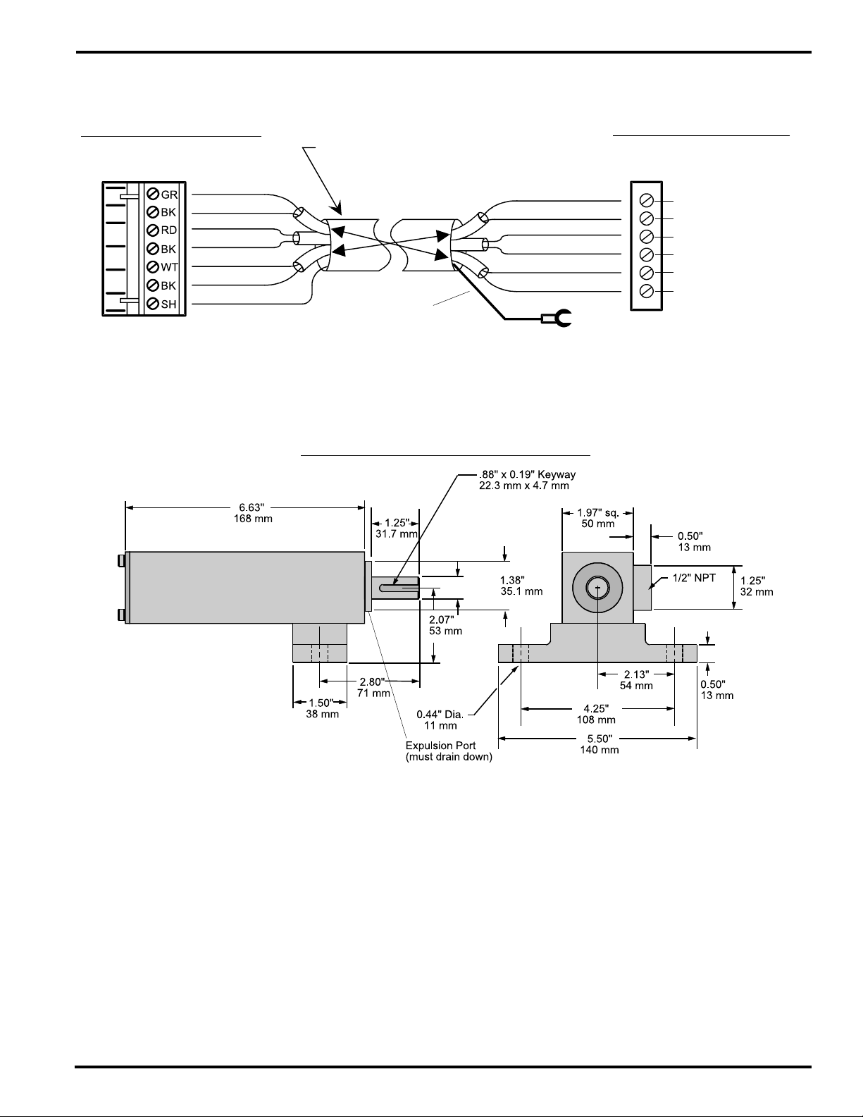
Resolver Wiring and Dimensions
STANDARD RESOLVER CABLES
PT# PS-5300-01-XXX (XXX = LENGTH IN FEET)
Connector - Controller End
PT# PS-5300-01-TER
(Weidmuller # BLA7 12822.6)
Cable Type:
Connector - Resolver End
PT# PS-5300-01-MSC
(ITT Cannon # KPT-06-F-12-10-S)
3 individually shielded pairs, 22 gauge
S2
Green
Black
Red
Black
White
Black
Shield
S4
S1
S3
R1
R2
Shield
(see note below)
Pin B - Green
Pin A - Black
Pin D - Red
Pin C - Black
Pin F - White
Pin E - Black
Shield
Shielding Note: Resolver cables made after 3-2-93 have a ring lug on a black shield wire at
the resolver end. The ring lug should be attached to one of the resolver connector strain relief
screws to protect against static discharge through the resolver cable. In some installations, it
may be advisable to disconnect the ring lug to prevent ground loops through the cable shield.
Consult Electro Cam if electrical noise problems are suspected.
RESOLVER DIMENSIONS
Foot Mount Resolver - 3/4" Shaft
Front View
(pin out)
= Not Used
With Rear Connector (shown):
PS-5275-11-ADR
With Side Connector:
PS-5275-11-ADS
Cable:
PS-5300-01-XXX where “XXX” is length in feet.
With Rear Connector (shown):
PS-5238-11-ADR
With Side Connector:
PS-5238-11-ADS
Cable:
PS-5300-01-XXX where “XXX” is length in feet.
0.749/
0.747"
19.02/
18.97 mm
Flange Mount Resolver - 3/8" Shaft
0.375/
0.374"
9.53/
9.50 mm
3-14 Wiring
Page 27
Resolver Wiring and Dimensions
STAINLESS STEEL RESOLVER
Cable for Stainless Steel Resolver with Terminal Strip Connections
Connector - Controller End
PT# PS-5300-01-TER
(Weidmuller # BLA7 12822.6)
Green
Black
Red
Black
White
Black
Shield
PT# PS-5300-02-XXX (XXX = Length in Feet)
Cable Type:
3 individually shielded pairs, 22 guage
White
Black
Black
Red
Black
Green
Shield
Shield
(see note below)
Shielding Note: This type of resolver cable will have a spade lug connected to the shield at the resolver end. The lug should
be attached to the grounding stud on the cover plate of the resolver. In some installations, it may be advisable to disconnect
the lug to prevent ground loops through the cable shield. Consult Electro Cam if electrical noise problems are suspected.
Connector Inside Resolver
(cable is stripped and tinned at
both ends)
WHITE
BLK (P/W) WHITE
BLK (P/W) RED
RED
BLK (P/W) GREEN
GREEN
Stainless Steel Foot Mount Resolver - 5/8" Shaft
Horizontal Mount
(shown) PS-5262-11-CTG (with right connector)
PS-5262-11-CTL (with left connector)
Vertical Mount (Shaft Up)
PS-5262-11-CTG-V (with right connector)
PS-5262-11-CTL-V (with left connector)
Cable: PS-5300-02-XXX where “XXX” is length in feet.
.625/
.624" dia.
15.88/
15.85 mm
For horizontal applications
3-15 Wiring
Page 28

Encoder Cable Installation
Encoder cable receptacle (male)
connectors are keyed to plug in
one way only
NON-TERM
TERM
Plug shield spade connector onto
NON-TERM lug if encoder is grounded
to the machine
Plug shield spade connector onto
TERM lug if encoder is not grounded to
the machine
Encoder compression
seal fitting
Spade connector for
cable shield
Connector for
encoder (female)
Turn it parallel to the
cable as shown to
slide it through the
encoder fitting
Split rubber sealing
grommet
Split nylon washer
Knurled compression
nut (threaded end
toward encoder)
Note: The encoder cable can be pulled through 3/4" or
larger conduit. Pull the cable from the controller to the
encoder. Turn the encoder connector (rectangular) parallel
to the cable (as pictured to the left) and tape it in this position
while it is being pulled. Pull the connector through conduit
before following the cable installation steps below.
A bulkhead connector assembly (PS-4300-09-XXX) is
available for installations where it is desirable to unplug the
encoder cable from the control enclosure.
Installation Procedure
1. Turn encoder connector (rectangular) parallel to cable
and slide knurled compression nut over it. Threaded end
of nut must face encoder connector.
2. Slip the nylon friction washer and the rubber sealing
grommet onto the cable by opening up the splits.
3. Turn encoder connector parallel to the cable and slide it
through the encoder compression seal fitting.
4. Plug encoder connector into the receptacle, making sure
that raised key on connector mates with the key slot in
the receptacle.
25 pin DB connector
(female)
Retainer screws must
be securely tightened
to insure proper
cable grounding
5. Plug the shield spade connector onto the “NON-TERM”
spade lug if the encoder is grounded to the machine, or
onto the “TERM” lug if the encoder is not grounded.
6. Slide the rubber grommet, nylon washer, and
compression nut up to the compression fitting. Thread
on the compression nut. Push a small amount of cable
into the encoder to insure that it isn’t pulling on the
connector as the compression nut is tightened.
7. Put lid back on encoder. Operating without the lid can
allow dust and other contamination to affect proper
operation of the encoder.
3-16 Wiring
Page 29

Programming Access Levels
Levels of Programming Access
The 5000 Series of controls have three levels of programming
access. Entry into these levels of programming is
accomplished through dedicated hardware inputs and/or
programmable enable codes entered through the keyboard.
Master Level—Accesses all programmable features. In
addition to all setpoints and functions, the Master Level also
establishes the keyboard entry codes for the “Setup” and
“Operator” access levels. Master Level programming also
determines which outputs are accessible to the operator.
NOTE: On units prior to date code 9740, operator access
was limited to setpoints and timed output values, unless
equipped with the Expanded Operator Access (-E) option.
Setup Level—Accesses all output setpoints and the
functions listed on the keyboard. These are control aspects
that may need occasional adjustment, but go beyond normal
operator responsibilities.
Operator Level—Functions available as specified in Master
Level programming. The operator is allowed to change the
following settings for output channels designated in FCN 6:
• Setpoints • Offset
• Timeouts • Active Program Number
• Motion Detection Settings • Speed Comp Settings
The table below details which functions and set points can
be changed at the three levels of programming access. It
also indicates if the programming access levels can be
accessed by hardware input and/or keyboard enable code.
FEATURE MASTER SET UP OPERATOR
Enable Method hardware code hardware / code
Output Set Points All All Selected
Output Time Out Values All All Selected
Motion Set Points Yes Yes Selected
Offset Yes Yes Selected
Active Program Yes Yes Selected
Speed Compensation Yes Yes Selected
Direction of Rotation Yes No No
Scale Factor Yes No No
Set Up Enable Code Yes No No
Operator Enable Code Yes No No
Time Base Selection Ye s No No
Motion ANDed Outputs Y e s No No
Select Operator Outputs Y es No No
Output Enable Modes Yes No No
OPTIONAL FEATURES:
Lead/Trail Speed Comp Yes No No
Communication Setup Ye s No No
Analog Setup Yes Yes Selected
Logic Terminal Strip
LOGIC COMMON
PROGRAM SELECT 1
PROGRAM SELECT 2
PROGRAM SELECT 3
MASTER PROGRAM ENABLE
OUTPUT GROUP ENABLE 1
MOTION DETECTION OUTPUT
OPERATOR PROGRAM ENABLE
+12VDC OUT - 150 mA MAX
Hardware Program Enable Circuits
1
2
3
4
5
6
7
8
9
10
Master Programming is enabled when terminal 6 is connected
to terminal 1 or 2. The Master Level can only be accessed by
energizing this input.
Operator Programming is enabled when terminal 9 is connected
to terminal 1 or 2. The Operator Level can also be accessed
through a keyboard enable code.
Keyboard Enable Codes for Setup and Operator Access
Either the Setup or Operator programming levels can be accessed by
entering the corresponding program enable code through the keyboard.
These codes can be 1, 2, 3, or 4 digit numbers and are established
during Master Level programming.
To Enter a program enable code number press:
FCN 0 ENT 1st digit 2nd digit 3rd digit 4th digit ENT
The PE codE message will disappear when a valid enable code is
entered.
The level of access gained depends upon which code number is
entered.
Programming access will time-out approximately 5 minutes after the
last keystroke. To cancel access before the 5 minute time-out press:
FCN 0 ENT CLR/CLE ENT
4-1 Programming, Standard Features
Page 30

Keyboard Layout, Keys and Indicators
2
1
1 - Function Key and Display
The FCN Key is used to access the controls functions. The
FCN number accessed will be displayed in the display next
to the FCN key.
2 - Program Key, LED and Display
The PGM key allows programs other than the current active
program to be viewed and or edited. The program number
selected for viewing/editing is shown in the display directly
above the PGM key. When the PGM LED is lit, the
program number displayed is also the current active
program.
3 - Channel Key, LED and Display
The CHN key allows the desired output channel to be
selected for setpoint viewing/programming. The selected
channel number is shown in the display directly above the
CHN key. When the CHN LED is lit, the channel currently
selected is in the ON state.
The CHN key is also used to select channel numbers during
Function programming. Details are given in the programming sections.
4 - Value Display, Position/RPM Key and LEDs, ON Key
and LED, PULSE Key and LED, OFF Key and LED, and
View Keys
The POS/RPM key selects between Position and RPM
being shown in the value display immediately to the left of
the key. The corresponding POS or RPM LED will be lit
when either item is displayed. Pressing the POS/RPM
allows programming functions to be exited/aborted
and returns the control to displaying Position or RPM.
The ON and OFF keys are used to specify the ON and OFF
pulse edges during setpoint programming. The
corresponding ON and OFF LEDs will be lit during these
3
6
4
5
setpoint programming operations. (The ON and OFF keys
and LEDs are also used when programming the optional
leading and trailing edge speed compensation feature).
The VIEW keys allow the current On and Off setpoints of the
currently selected channel to be displayed in sequence, one
at a time. The corresponding ON or OFF LED will be lit to
indicate whether an ON or OFF edge is currently displayed.
The >VIEW key displays the setpoints in increasing numeric
order, the <VIEW key displays them in decreasing numeric
order.
The PULSE key allows setpoint pairs (pulses) to be
incremented and decremented simultaneously. When the
PULSE LED is lit steadily, the pulse (both edges) whose
edge is currently displayed will increment and decrement
when the INC and DEC keys are pressed. Pressing the
PULSE key a second time will cause the LED to blink. This
indicates that the multi-pulse mode is activated and all of the
pulses in the currently selected output channel will increment
and decrement when the INC and DEC keys are pressed.
5 - MOTION, POWER and CPU LEDs
The Motion LED is lit whenever the machine speed is within
the current motion setpoints (FCN 1).
The Power LED is lit whenever the PLuS control is powered
up.
The CPU LED only lights when a Fatal error condition is
detected by the controller. A list of these error conditions is
detailed on page A-5 of this manual.
6 - Numeric Keys, CLR/CLE Key, ENT Key, INC and DEC
Keys
The number keys are used to input all numeric values
needed during setpoint and function programming.
The CLR/CLE key is used to clear numeric values during
programming operations.
The ENT key is used to actually enter numeric values into
the controller after they have been keyed in. Failing to press
ENT when programming numeric values will result in the old
value remaining in the control's memory. Numeric value
changes must be “Entered” by pressing the ENT key before
they are accepted by the controller.
The INC and DEC keys cause numeric values that are
displayed in the controls POS display to be incremented
and/or decremented each time the corresponding key is
pressed. Output setpoints, speed compensation and timed
output values are examples of items that can be incremented
and decremented with the INC and DEC keys.
4-2 Programming, Standard Features
Page 31

Output Setpoint Programming
OFF
FCN
PGM
CHN
POS
Programming Error Messages
Flashing error messages indicate programming mistakes
as they occur.
Simply press to cancel flashing error message.
E1 OLAP: Output pulse just attempted overlapped an existing output
E2 -run: Attempted programming can NOT be done while machine is
E4 -Pro: Program enable Off when programming was attempted.
E5 8888: Value entered NOT valid for item being programmed.
E6 -379: Invalid setpoint entered: A setpoint ending in 3, 7, or 9 was
E7 -dEF: Attempted to program too many Enable Inputs (FCN 9).
E9-tdE: Attempted to program too many timed outputs (FCN 5).
E11-ScE: Attempted to program more than 16 speed compensated
CLR
pulse on same channel.
running (transducer is turning).
entered. (Encoder Only - Exceptions: 89, 179, 269, and 359)
outputs (48 I/O controls only).
See pgs. A-12 thru A-14 for more details on error messages.
Output Setpoint Programming
Desired output channel MUST be selected before its
setpoints can be created, viewed, adjusted, or cleared.
If POS or RPM
led NOT lit press:
POS or RPM
led now lit
SELECT OUTPUT CHANNEL
POS
RPM
CHN
CHN and POS
displays blank
1st Digit shown
in CHN display
Channel 16 used as example.
1
6
2 Digit value in
CHN display
To create setpoints in output channel presently selected.
ON
On led lit, POS
blank
3
1st Digit shown in
POS display
0
2 Digits shown in
POS display
On at 30 degrees used as example.
6
OFF led lit, POS
blank
1st Digit shown in
POS display
Off at 60 degrees used as example.
Note: When entering multiple pulses, press
pulse.
2 Digits shown in
POS display
0
ENT
ENT
POS display blinks
once to confirm
setpoint entry.
after each
CHANGE SETPOINTS
CREATE SETPOINTS
To change setpoints in output channel presently selected.
INC/DEC
INC
Displayed ON/OFF setpoint increases 1
increment each time INC key is pressed.
INC
DEC
Displayed ON/OFF setpoint decreases 1
increment each time DEC key is pressed.
DEC
NUMERIC ENTRY
5
1st Digit shown in
POS display
0
2 Digits shown in
POS display
Changing setpoint to 50 degrees used as example.
ENT
POS display blinks once to
confirm setpoint change.
PULSE MODE
To change both setpoints of a pulse simultaneously.
PULSE
Pulse led lit
INC
ON and OFF setpoints of ALL pulses
increase/decrease 1 increment each
time INC/DEC key is pressed.
OR
DEC
MULTI-PULSE MODE
To change all setpoints in the output channel simultaneously.
PULSE
Pulse led lit
PULSE
Pulse led
blinking
ON and OFF setpoints of ALL pulses
increase/decrease 1 increment each
time INC/DEC key is pressed.
INC
OR
DEC
CLEAR SETPOINTS
CLEAR 1 PULSE
To clear 1 pulse (1 pair of setpoints) on selected output channel.
Use numeric entry method (shown in CHANGE SETPOINTS above) to set OFF setpoint equal to ON setpoint
value. Both setpoints will be erased.
View setpoints of output channel presently selected.
VIEW
ON/OFF setpoints shown in position
display in increasing order with ON
and OFF LEDs. 0 is shown and both
LEDs off if no setpoints exist.
VIEW
ON/OFF setpoints shown in position
display in decreasing order with ON
and OFF LEDs. 0 is shown and both
LEDs off if no setpoints exist.
4-3 Programming, Standard Features
VIEW SETPOINTS
CLEAR EXISTING SETPOINTS
To clear all setpoints on selected output channel.
VIEWVIEW
ON
ON Led lit,
POS blanks
0
0 shown in
POS display
OFF
OFF Led
lit, POS
blanks
0
0 shown in
POS
display
ENT
POS display
blinks and
shows 0, ON
and OFF LEDs
are off.
Page 32
Master Level Programming, Standard Controls: FCN 0
FCN 0 Programming at the Master Level
(Master Program Enable Input MUST be energized)
Function 0 allows specific features of the PLµS control to be
programmed when the Master Program Enable input is
energized. Standard Function 0 features include: Direction
of Increasing Rotation, Scale Factor, Set-up Enable Code,
Operator Enable Code, and Output Timing Resolution.
Normally, the features controlled by Function 0 will be
programmed only once for a specific application.
Optional Function 0 features are covered under
“Options Programming,” Section 5. They include: Sc
(leading/trailing edge speed comp), ct (communication
type), cS (communication Speed), cA (communication
Address), and rU (RPM update frequency).
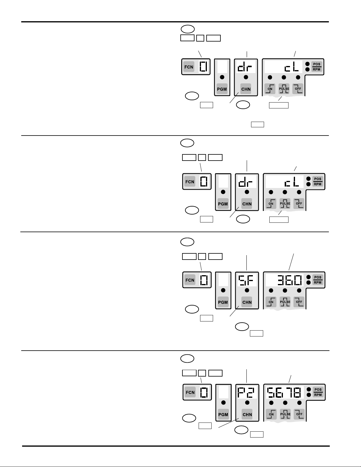
dr - Direction of Increasing Rotation
This allows the direction of increasing rotation of the position
transducer (encoder / resolver) to be cL (clockwise) or ccL
(counter clockwise) as required by the machine installation.
This is normally set so the position value increases when
the machine turns in its forward direction.
Resolver: cL or ccL as viewed from shaft end.
1st Press:
FCN 0 ENT
FCN 0 Shown
2nd
Press CHN key
to step through the
FCN 0 features
1st If FCN 0
not shown press:
FCN 0 ENT
FCN 0
Feature being
Programmed
3rd
Press PULSE key to select
desired choice OR
Press numeric keys followed by
ENT key to change values
dr - direction
of increasing
rotation
Present Value / Choice
for displayed FCN 0
feature shown
Present direction
shown:
cL - clockwise
ccL - counter clockwise
Encoder: cL or ccL as viewed from shaft end with cable
entrance on the right.
SF - Scale Factor (Resolver units only)
The Scale Factor is the number of increments each revolution
of the resolver will be broken into. A Scale Factor of 360 (0-
359) allows programming to be done in degrees. A Scale
Factor of 1024 (0-1023) allows setpoint programming to be
done at fine resolution (.35 degree increments).
Scale Factors range from 2-1024 on standard 5000 controls.
Scale Factors range from 2-4096 on high resolution 5000
controls (“H” option).
Note: When Scale Factor is changed, all programmed
setpoints are recalculated to convert them to the new Scale
Factor. The keyboard will be inoperative during this time.
Scale Factor value will blink once when calculation is
completed.
P1 & P2 Keyboard Enable Codes
P1 - Setup Enable Code Number
P2 - Operator Enable Code Number
2nd
Press CHN key
until dr is shown
1st If FCN 0
not shown press:
FCN 0 ENT
2nd
Press CHN key
until SF is shown
1st If FCN 0
not shown press:
FCN 0 ENT
3rd
Press PULSE key to select
between cL and ccL
SF Scale Factor
3rd
Press number keys followed by
ENT to change Scale Factor
value (change will take time)
P1 or P2
selected
Present Scale Factor
value shown
Present Enable Code
value shown for P1 or
P2 code selected
These are the keyboard entry code numbers that will be
used to access the Setup (P1) and Operator (P2)
programming levels.
Any 1, 2, 3, or 4 digit value can be used for either P1 or P2.
4-4 Programming, Standard Features
2nd
Press CHN
key until desired P1
or P2 is shown
Press number keys followed by
3rd
ENT to change Enable Code
value
Page 33
Master Level Programming, Standard Controls: FCN 0 (continued)
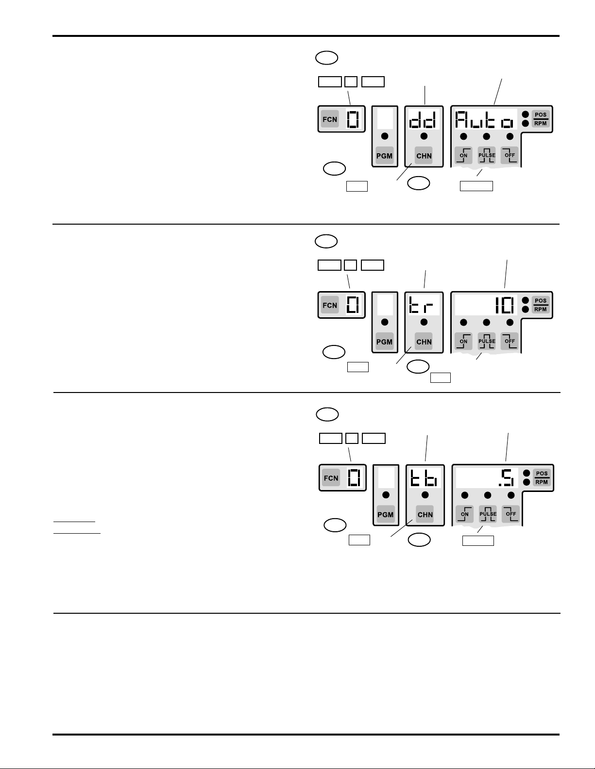
dd - Display Default (PS-51XX after 5/12/92)
Auto, Spd, or PoS can be selected for the display default by
pressing the Pulse key while “dd” is displayed in function 0.
Auto - (Automatic) Display will automatically switch between
POS and RPM when speed goes above and below the “tr”
(toggle RPM) value programmed.
Spd - (Speed) On power up, the control will default to
displaying RPM. The POS/RPM key can be used to switch
between position and RPM display.
PoS - (Position) On power up, the control will default to
displaying position. The POS/RPM key can be used to
switch between position and RPM display.
tr - Toggle RPM (All units after 5/12/92)
When the “Auto” mode is selected as the “dd” (display
default), the value programmed in “tr” determines the speed
where the display switches from position to RPM.
At speeds below “tr”, position will be displayed and the
“POS” LED will be lit.
At speed equal to or above “tr”, RPM will be displayed and
the “RPM” LED will be lit.
1st If FCN 0
not shown press:
FCN 0 ENT
2nd
Press CHN key
until dd is shown
1st If FCN 0
not shown press:
FCN 0 ENT
2nd
Press CHN key
until tr is shown
dd
display default
selected
3rd
Press PULSE key to select
Auto, Spd, or Pos
tr
toggle rPM
selected
3rd
Press number keys followed by
ENT to change toggle RPM
Present display
default (dd) shown
Present toggle RPM
value shown
tb - Time Base Used for Output Timing
The timing resolution is selectable between 1 mSec and .5
mSec increments on 8, 9, and 16 output controls (24 and 48
output controls have a fixed 1 mSec tb and do not display
tb in FCN 0). All timed outputs use the same time base.
Timing accuracy of all timed outputs is -0, +1 tb increment.
The number of outputs that can be timed is affected by the
time base selected: (24 and 48 output systems can time up
to 4 outputs)
1mSec tb - Up to 8 outputs can be timed (.001 - 9.999 Sec)
.5 mSec tb - Up to 4 outputs can be timed (.0005 - .9995
Sec)
Note: Adding too many timed outputs will cause an E9
programming error. The “.5” tb value will flash and cannot
be selected if more than 4 timed outputs already exist in
FCN 5.
Consult factory if more timed outputs are required.
Enhanced Position/RPM Display Logic
All PS-51XX (Resolver) Series controls made after 5/12/92
include a feature that allows the user to program the display
default to RPM, position, or automatically switch between
RPM and position. Previous controls always defaulted to
displaying RPM with the POS/RPM key, allowing manual
selection of the item displayed. The POS/RPM key still
1st If FCN 0
not shown press:
FCN 0 ENT
2nd
Press CHN key
until tb is shown
tb
time base
3rd
Press PULSE key to select
1 or .5 mSec Time Base (.5 will
flash if more than 4 timed outputs
exist in FCN 5)
Present Time Base
value shown
allows manual selection of the item displayed on the PS5000 versions with the new display logic.
To control these display features, two items have been
added to FCN 0 programming : dd (display default) and tr
(toggle RPM).
4-5 Programming, Standard Features
Page 34
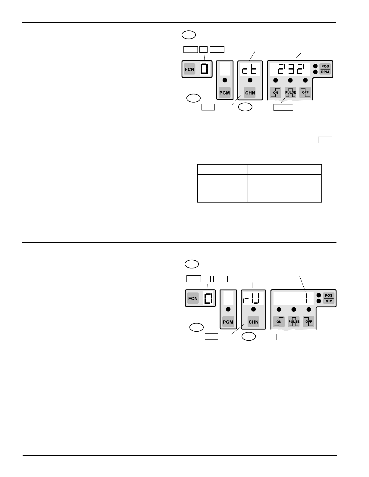
ct, cS, cA - Communication Parameters
ct - communication type: Specifies the type of
communication port being used by the PLµS control. It
contains both an RS-232 and an RS-485 port. RS-485 is
the default setting. Both of these ports share the DB-9
connector located at the top of the power supply section.
The type of port being used on the PLµS must match the
type of port being used by the device communicating with
the PLµS.
cS - communication Speed: Specifies the baud rate (bits
per second) that the PLµS communication port will operate
at. It must be set for the same baud rate as the device
communicating with the PLµS control. The choices are:
4800, 9600, 19200, and 38400 baud. 9600 is the default
setting.
cA - communication Address: Each control can have
a unique communication address (0-255) because multiple
controls can be wired to the same host device in a RS-485
network. This allows the host to send information to a
specific control while the other controls will ignore the
information. A PLµS control will ignore incoming information
if the address that information specifies does not match the
communication address of the control.
1st If FCN 0
not shown press:
FCN 0 ENT
2nd
Press CHN key
to choose ct, cS, or
cA
Comm Item Choices
ct (port type) RS-232, RS-485
cS (baud) 4800, 9600, 19200, 38400
cA (comm add) 0-255; 1 is default
Default settings are shown in bold face.
ct - comm type
cS - comm speed
cA - comm Address
3rd
Present value for
selected comm
item selected
Press PULSE key to select
desired option when ct or cS are
selected
When cA is selected press
number keys followed by ENT
to change comm address
NOTE: On units manufactured prior to date code 9740,
the Communications Parameters (-C) option was
required for communications features.
rU - rPM Display Update Frequency
This function determines the frequency with which the
display of RPM is updated.
1 Display updates RPM once per second
2 Display updates RPM twice per second
10 Display updates RPM ten times per second
NOTE: On units manufactured prior to date code 9740,
the Expanded Operator Access (-E) option was required
for rPM Display Update Frequency (rU).
Viewing / Changing Program Banks
1st If FCN 0
not shown press:
FCN 0 ENT
2nd
Press CHN key to
select rU
rU
rPM Update
selected
3rd
Present rPM Update
frequency shown
Press PULSE key to select
desired update frequency.
4-6 Programming, Standard Features
Page 35
Master Level Programming, Standard Controls: FCN 6 & FCN 7
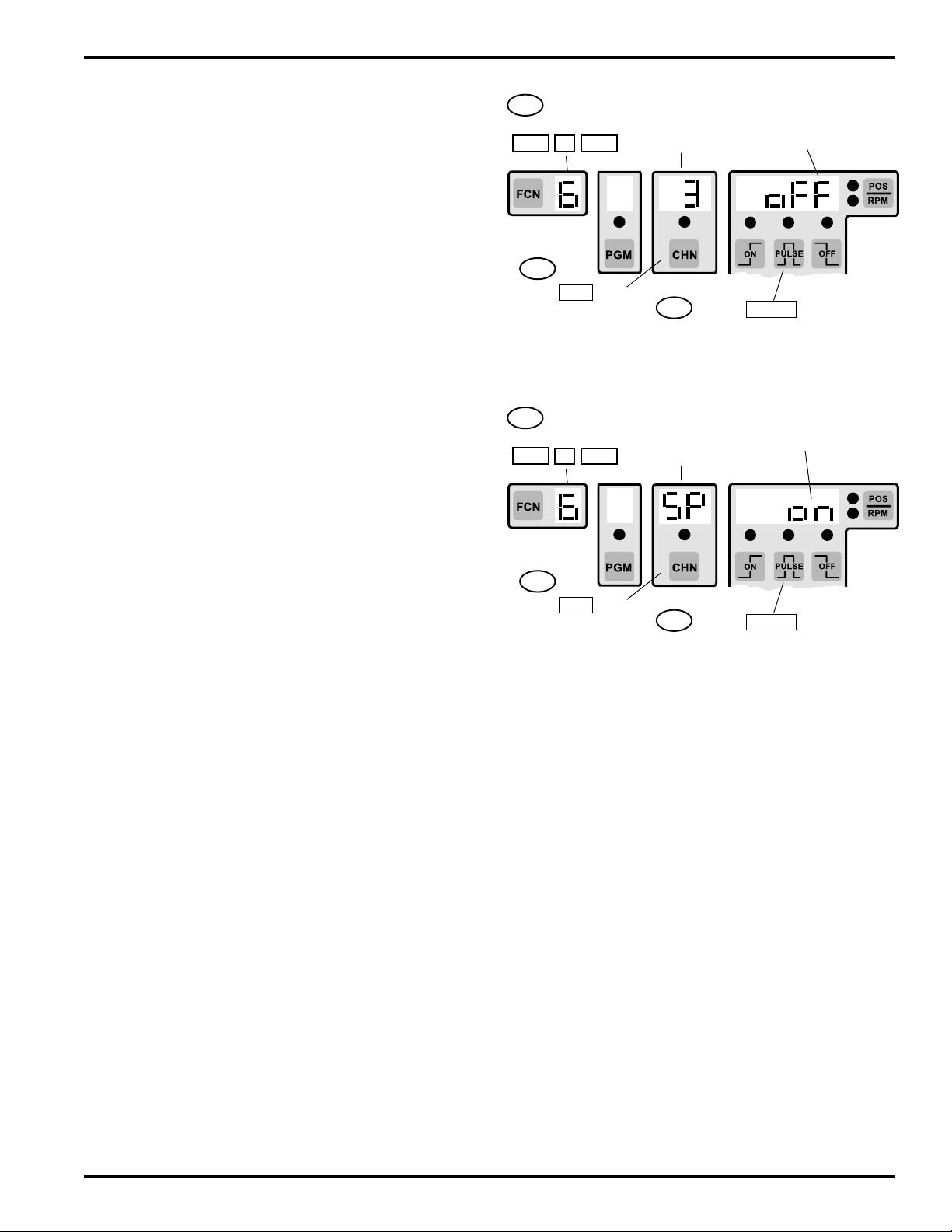
FCN 6 - Operator Access
(Master Program Enable Input MUST be energized)
This function selects which features can be adjusted at
the Operator access level. Step through them one at a
time, and select On or Off according to whether or not
the Operator should be able to adjust them.
Functions that are not Channel-Specific:
Sd—Speed Detection (FCN 1, Motion Setpoints and Analog
Parameters if control has the “-A” option)
on Operator can adjust FCN 1 values
oFF Operator cannot adjust FCN 1 values
oF—Offset (FCN 2)
on Operator can adjust offset values
oFF Operator cannot adjust offset values
AP—Active Program (FCN 3)
on Operator can change program number
oFF Operator cannot change program number
Functions that are Channel-Specific:
The following functions—“SP,” “Sc,” and “to”—will be
adjustable only for those channels turned “on“ through
“Output Channel Selection.”
Output Channel Selection
on Operator can adjust values in this channel
oFF Operator cannot adjust values in this channel
Setting Output Channel Access
1st If FCN 6
not shown press:
FCN 6 ENT
2nd
Press CHN key
to select Output
Channel
Output
Channel
selected
3rd
Operator Enable status
shown for selected
output channel
Press PULSE key to toggle
Enable Status on and off
Setting Operator Accessible Functions
1st If FCN 6
not shown press:
FCN 6 ENT
2nd
Press CHN key
to select function
SP, Sd, oF,
AP, Sc, or to
selected
3rd
Operator Enable status
shown for selected
function
Press PULSE key to toggle
Enable Status on and off
SP—Setpoints
on Operator can adjust setpoints
oFF Operator cannot adjust setpoints
Sc—Speed Compensation (FCN 4)
on Operator can adjust speed comp values
oFF Operator cannot adjust comp values
(Encoder-based controls with the “-E” option have
Negative Speed Compensation capabilities, page 4-9.)
to—Timed Outputs (FCN 5)
on Operator can adjust timed outputs
oFF Operator cannot adjust timed outputs
NOTE: On units manufactured prior to date code 9740,
operator access was limited to setpoints and timed
ouput values, unless equipped with the Expanded
Operator Access (-E) option.
4-7 Programming, Standard Features
Page 36

FCN 7 - Motion ANDing of Output Channels
(Master Program Enable Input MUST be energized)
This function selects which output channels will be ANDed
1st If FCN 7
not shown press:
FCN 7 ENT
Present output
channel
selected
Present Motion ANDing
status shown for output
selected
with the Motion setpoints as programmed in FCN 1. ANDed
outputs will be on during their programmed pulses only if the
RPM is within the Motion setpoints. In order for Motion
ANDing to take affect, “On” and “Off” pulses must be
programmed into the selected channel.
An output channel can be turned into a motion detector by
programming it to be “On” at 1, “Off” at 1, and then ANDing
it with the Motion setpoints. Setting both points at 1 will turn
the output on for a full 360°. By ANDing this output to the
2nd
Press CHN key
to select output #
3rd
Press PULSE key to select
between on and oFF
Motion setpoints, the output will be on constantly as long as
the RPM is within the Motion setpoint range.
on - Output is disabled IF present RPM is not within Motion
setpoints.
oFF - Output will cycle on and off at programmed position
setpoints regardless of present RPM.
Note: Once programmed in a channel, this function will be present in that channel in all programs.
4-8 Programming, Standard Features
Page 37
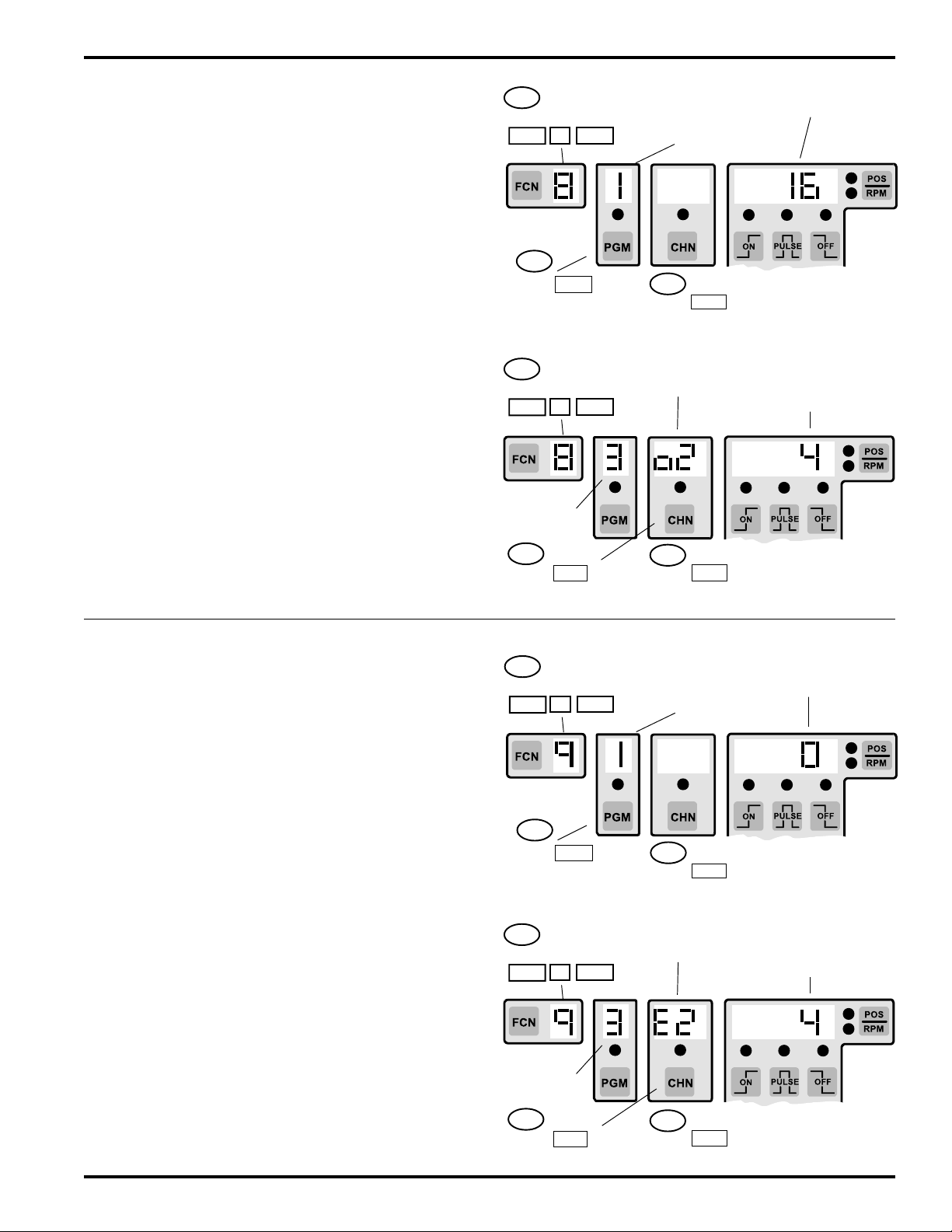
Master Level Programming, PS-5XX4 Only: FCN 8 & FCN 9
FCN 8 - Subdividing Outputs into Groups
(Master Program Enable Input MUST be Energized)
The outputs can be subdivided into as many as eight output
groups. The number of output groups and the number of
outputs in each group is determined by FCN 8.
Each output group can be set at a unique degree position
through FCN 2 (CHN key selects Output group #).
When more than one output group exists the POS/RPM key
will individually display each group's position by showing
the group number above the CHN key while showing the
current position next to the POS/RPM key.
When the number of outputs in each group is being assigned,
all of the outputs must be accounted for. The last output
group will automatically contain the outputs remaining after
the number of outputs in the other groups is defined. The
number of outputs in the last group automatically changes
if the total number of outputs in the other groups is changed.
Each output group can have a dedicated enable input and
be assigned to operated in any one of the Output Enable
Modes. See FCN 9 for programming Enable Inputs and
Modes.
See Output Grouping and Enable Modes section in the
appendix of this manual for further information on output
grouping.
Note: Once programmed in a channel, this function will
be present in that channel in all programs.
Programming the Number of Output Groups
1st If FCN 8
not shown press:
FCN 8 ENT
2nd
Press PGM key
(Number of Output
Groups blinks)
Present
number of
Output Groups
3rd
Press number key followed by
ENT to change number of output
groups (1-8)
Present number of
outputs
Programming the Number of Outputs in Each Group
1st If FCN 8
not shown press:
FCN 8 ENT
Number of
Output
Groups
2nd
Press CHN key to
select Output Group #
Output Group
# selected
3rd
Press number key followed by
ENT to change number of
outputs in selected group
Present number of
outputs in selected
Output Group
FCN 9 - Enable Inputs and Enable Modes
(Master Program Enable Input MUST be Energized)
The number of Enable Inputs and the mode of operation for
each output group with an Enable input is determined by
FCN 9.
The 1st Enable Input (Output Group Enable 1) is located on
the Logic terminal strip. If additional Enable Inputs are
programmed, they will be input modules on the I/O rack,
starting in order from the first module position (Group 2
Enable: module position 1; Group 3 Enable: module position
2; etc.). Each additional Enable Input reduces the available
outputs by one, and automatically reduces the last output
group by one output.
Brief Summary of Enable Modes:
Mode 0 - Normal PLS operation, no Enable Input.
Mode 1 - Enable Input causes Group position to re-zero.
Mode 2 - Enable Input causes Group position to re-zero
and enables outputs to cycle during next
revolution.
Mode 3 - Group outputs are on only if Enable Input is on.
Mode 4 - Enable Input (within enable window) enables
outputs to cycle during next revolution; group
position does not re-zero.
Modes 1, 2, and 4 require enable windows to be programmed.
Channel 91 is enable window for Group 1, channel 92 for
Group 2 and etc. See Enable Modes in appendix for details.
Programming the Number of Enable Inputs
1st If FCN 9
not shown press:
FCN 9 ENT
2nd
Press PGM key
(number of Enable
Inputs blinks)
Present
number of
Enable Inputs
3rd
Press number key followed by
ENT to change number of
Enable Inputs
Present Enable Mode
of Enable input
Programming Output Enable Modes
1st If FCN 9
not shown press:
FCN 9 ENT
Number of
Enable
Inputs
2nd
Press CHN key to
select Enable Input
Enable Input #
Selected
3rd
Press number key followed by
ENT to change Enable Mode of
Enable Input selected
Present Enable
Mode of Selected
Enable Input
4-9 Programming, Standard Features
Page 38
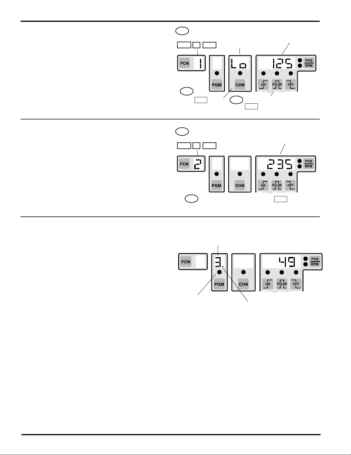
Setup Level Programming, Standard Controls: FCN 1, FCN 2, FCN 3
FCN 1 - Motion Setpoints
(Setup or Master program enable must be active)
Motion logic is active whenever the present RPM is between
1st If FCN 1
not shown press:
FCN 1 ENT
Lo or Hi
RPM setpoint
selected
Present RPM value for
selected setpoint
shown
or equal to the Low and High motion setpoints. Motion logic
can be selectively ANDed with outputs (FCN 7) and also
controls the “Motion Detection Output” on the Logic terminal
strip. The Motion LED on the keyboard is lit when the Motion
logic is on.
Lo - Low RPM setpoint for motion
Hi - High RPM setpoint for motion
Ao, Ah (analog) covered in Options Programming section.
2nd
Press CHN key
to select Lo or Hi
3rd
Press number keys followed by
ENT to change RPM Setpoint
Note: Once programmed in a channel (FCN 7) this function will be present in that channel in all programs.
FCN 2 - Offset
(Setup or Master program enable must be active)
The Offset function allows the controller position to be set
1st If FCN 2
not shown press:
FCN 2 ENT
Present Control
Position shown
to match the position of the machine. This eliminates the
need to mechanically adjust the position of the resolver/
encoder shaft to match the machine position.
To set the Offset, simply stop the machine in a known
position and enter that known machine position value into
FCN 2. The position display on the control will match the
2nd
machine position at all times when the Offset is correctly set.
Press number keys followed by ENT to match
Control Position to present machine position
FCN 3 - Program Number
(Setup or Master program enable must be active)
The Active Program is the program (machine setup) which
is currently controlling the outputs. The total number of
programs available are subdivided into groups of eight
which are called Program Banks. Each Program Bank
contains eight individual programs.
When all Program Select inputs are off the keyboard selected
Active Program will be active.
The number of Program Banks available varies with the
number of outputs the control has as follows:
8-16 outputs - 8 Banks - 64 Programs total
24 outputs - 6 Banks - 48 Programs total
48 outputs - 3 Banks - 24 Programs total
A convenient Program number (Pn) feature allows the
desired program number (1-64) to be viewed or entered
directly without having to enter the corresponding values
into the Program bank (Pb) and Active Program (AP)
parameters. This is the method described below under
“Viewing or Changing Program Numbers from Keyboard.”
Normal Display of Program Number
Program Number
If LED is lit, the
program number
shown is active,
regardless of which
bank it is in.
If LED is off, the
program number
shown is not active.
To determine active program and bank number, or to
switch programs, use FCN 3, next page.
If decimal point is present, the
active bank is not Bank 1; use
FCN3, Pb to determine bank #.
If decimal point is absent, active
bank is Bank 1.
NOTE: On units manufactured prior to date code 9740,
active program was limited to Program Bank (Pb) and
Active Program (AP), unless equipped with Expanded
Operator Access (-E) option.
4-10 Programming, Standard Features
Page 39
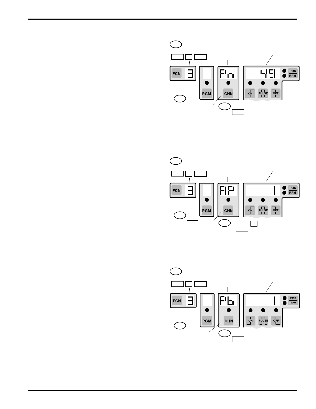
Setup Level Programming, Standard Controls: FCN 1, FCN 2, FCN 3
If the hardware program select inputs are going to be used
to select programs (they can be driven from a PLC or
selector switch), it may be necessary to program the Program
bank (Pb) and Active Program (AP) from the keyboard.
Follow the instructions given below under “Hardware
Selection of Program Number.”
Viewing or Changing Active Program Number from
Keyboard
Use the Program number (Pn) feature of FCN 3 to see the
active program number or select any program directly by
entering the corresponding number from 1-64. The
corresponding “Pb” and “AP” values will automatically be
calculated and selected. It will not be necessary to calculate
or program “Pb” or “AP”, but they can be viewed to verify that
their values correspond to the selected program number.
Pn— Program number (1-64)
Pb— Program bank (1-8); 8 banks of 8 programs each
AP— Active Program (1-8); active program within bank
Example:
If Program number (Pn) 34 is selected, “Pb” will equal five
(5th bank of eight programs) and “AP” will equal two (2nd
program within this bank).
DO NOT enter values into “Pb” or “AP” if the keyboard
program selection is being used. Simply program “Pn” to the
desired program number from 1-64.
Viewing/Changing Program Number
1st If FCN 3
not shown press:
FCN 3 ENT
2nd
Press CHN key
to select Pn
Pn
Program
number
3rd
Press number keys followed by
ENT to change active Program
number. (1-64 are valid Program
numbers)
Present Program
number shown
Viewing/Changing the Active Program
1st If FCN 3
not shown press:
FCN 3 ENT
AP
Active
Program
Present Active Program
number shown
Hardware Selection of Program Number
The hardware program select inputs override the keyboard
programmed Active Program (AP) value when any one or
combination of the inputs is energized. When the hardware
inputs are used to select the Active Program (AP), insure
that “AP” is set equal to one.
The hardware select inputs only affect the current “AP”
value that is controlling the outputs. The “Pb” is not affected
by the select inputs and has to be changed from the
keyboard if more than eight programs are used.
To summarize, hardware select inputs can select which of
the eight programs in the current program bank is controlling
the outputs, but changing the program bank number must
be done through the keyboard by programming “Pb.”
Note: Active Program and Program Bank can be changed
through the serial communication port also.
2nd
Press CHN key
to select AP
3rd
Press 1 key followed by
ENT to change active Program to 1.
Viewing/Changing Program Banks
1st If FCN 3
not shown press:
FCN 3 ENT
2nd
Press CHN key
to select Pb
Pb
Program
bank
3rd
Press number keys followed by
ENT to change Program Bank
Present Program Bank
number shown
4-11 Programming, Standard Features
Page 40

Setup Level Programming, Standard Controls: FCN 4
FCN 4 - Speed Compensation
(Setup or Master program enable must be active)
Speed Compensation is the ability of the control to
automatically advance an output's setpoints as the machine
speeds up, thus compensating for the response of the
device being controlled. Each output can be individually
compensated by a unique amount. This allows all output
devices to be properly compensated, even though their
responses may vary widely.
Standard speed compensation advances and retards both
the on and off edges of output pulses by the same amount,
proportional to the present machine speed.
Leading/Trailing Edge speed compensation, available on
controllers with the “L” option, allows a different amount of
compensation to be set for the leading and trailing output
edges in each channel. See page 5-1 for details.
Gray Code speed compensation is available on controllers
with the “G” option. See page 5-3 for details.
Speed compensation is set in units of Degrees/1000 RPM,
regardless of the scale factor being used. If the response of
the output device is known, the amount of Speed Comp
required can be calculated:
Speed Comp (Deg/1000 RPM) = 6 x response (in mSec)
EX: 20 mSec response: 6 x 20 = 120 (Deg/1000 RPM)
Program the output for the correct on and off setpoints at
zero speed and then program speed comp value.
If the device response is not known, program output for the
correct on and off setpoints at zero machine speed. Program
1st If FCN 4
not shown press:
FCN 4 ENT
2nd
Press CHN key
to select output #
Present Output
Channel
Selected
3rd
Press number keys followed by
ENT to change Speed Comp
value
OR
DEC and INC keys can be
used to adjust Speed Comp
value in 1Deg/1000 RPM steps.
Present Speed Comp
value for selected
output channel shown
the output with an estimated speed comp value based on
six times the estimated response in mSec (mSec = .001
Sec). Run the machine at a typical speed and adjust Speed
Comp until the output is properly synchronized to the
machine.
Note: 1 Degree/1000 RPM resolution allows Speed Comp
to be adjusted very accurately. Because the adjustment is
so fine, it may be necessary to make larger changes to the
Speed Comp value to see a change in machine performance.
A change of 6 degrees/1000 RPM is needed to make a 1
mSec difference to the device being controlled.
FCN 4 - Negative Speed Compensation
(Input Gating)
Example: Assume a product sensor requires 5 msec to
respond, and an output channel provides a reference window
to a PLC. The PLC will trigger an action only if the sensor
(Setup or Master program enable must be active)
This feature is included on the following units which
were built after 5-19-92, date codes 9222 or greater. The
date code is printed beneath the model code on the
label on the back of the controller:
• All PS-51XX (Resolver) units
• All PS-50XX (Encoder) units date code 9740 or
newer, and units with "E" option prior to 9740.
Negative Speed Compensation causes an output channel
to lag its programmed machine position by the specified
degrees/1000 RPM. It is used when an input sensor is being
indicates a product is present during the output channel‘s
reference window. At 1000 RPM, the resolver will rotate (5
msec x 6), or 30 degrees during the sensor response time.
If the reference window isn’t also delayed by 30 degrees per
1000 RPM, the sensor signal may miss the reference
window.
Negative Speed Compensation is programmed in Deg/
1000 RPM. If the response of the input device is known, the
amount of Negative Speed Compensation needed can be
calculated:
Speed Comp (Deg/1000 RPM) = 6 x response (in mSec)
EX: 10 mSec response -6 x 10 = -60 (Deg/1000 RPM)
gated by the corresponding output channel into another
system (PLC, registration control, etc.) Since most sensors
have very fast response times, negative speed comp is
needed only where the sensor is slow to respond, or the
machine speeds are high and sensor timing is critical.
Because the PLuS control has individual speed
compensation for each output channel, it is possible to have
some outputs compensated positively while others are set
for Negative Speed Compensation.
(continued next page)
Note: Once programmed in a channel, this function will be present in that channel in all programs.
4-12 Programming, Standard Features
Page 41
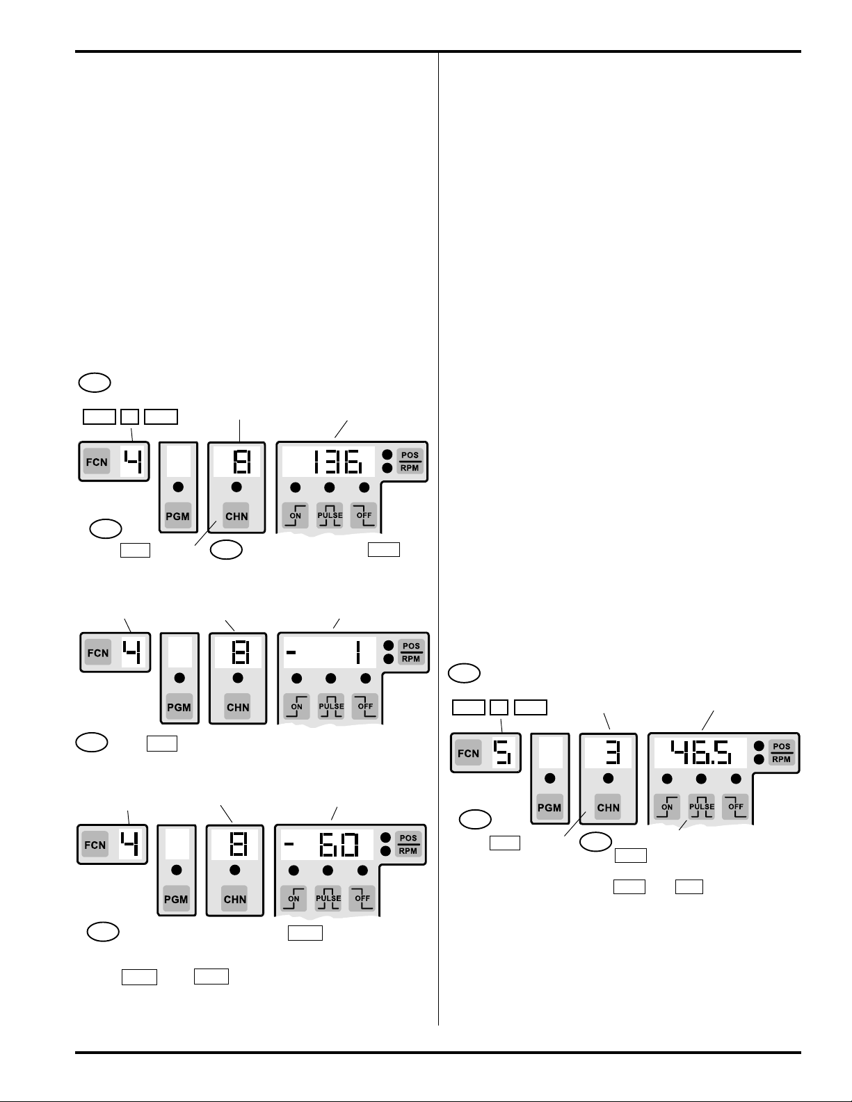
Setup Level Programming, Standard Controls: FCN 4 & FCN 5
FCN 4 - Negative Speed Comp (continued)
In order to activate Negative Speed Compensation, the
corresponding channel must first be set equal to “0” speed
compensation in FCN 4, and then decremented by pressing
the DEC key. Speed compensation for that channel will then
stay in the negative mode until it is set back to “0” speed
compensation.
Whenever Negative Speed Compensation is programmed,
the speed compensation value shown in the position display
will have a minus (“-”) sign in the left-most digit.
Note: To restore Positive Speed Compensation set the
compensation value back to 0. Then key in desired amount
of Positive Speed Compensation.
To Program Negative Speed Comp:
1st If FCN 4
not shown press:
FCN 4 ENT
2nd
Press CHN key to
select output #
Then. . .
FCN 4 shown
Present Output
Channel Selected
3rd
Present Output
Channel Selected
Press 0 key followed by ENT to
change Speed Comp value to 0
Present Speed Comp
value for selected output
channel shown
Present Speed Comp value for
selected output channel shown
FCN 5 - Timed Outputs
(Setup or Master program enable must be active)
Outputs can be turned off after a specified time duration,
instead of staying on until the off position setpoint is reached.
Any output can be timed, and each timed output can specify
a unique time dwell. This is appropriate for devices which
require a specific output time, regardless of machine speed.
Timed outputs are programmed like standard outputs with
“on” and “off” position setpoints specified. A timed output will
turn on at the specified “on” position setpoint, and will turn
off after the specified time delay or when the “off” position
setpoint is reached, whichever occurs first. If the time out
value is set to zero, the output will not be timed.
If an E9 tdE error message occurs, too many timed outputs
exist for the current time base selected. Either reduce the
number of timed outputs or change the time base being
used. See tb section of FCN 0 programming (page 4-5) for
details.
To calculate output timing, use the following relationships:
RPM x 360 = Degrees per Minute
Degrees per Minute ÷ 60 = Degrees per Second
Degrees per Second ÷ 1000 = Degrees per msec
Therefore: RPM x .006 = Degrees per msec
Example: Suppose a timing dwell of 20 msec has been
established. At 1000 RPM, the transducer will rotate:
1000 x .006, or 6° per msec
During the 20 msec dwell time, the transducer will rotate
120° at 1000 RPM.
Time-out value (mSec)
for selected output
(0 = No Time-out)
Decimal is automatically
inserted for 0.5mSec
Time Base.
4th
Press DEC key to change Speed Comp value from 0 to -1
Then. . .
FCN 4 shown
5th
Press number keys followed by ENT to program
desired Negative Speed Comp value
DEC and INC keys can be used to adjust Speed
Comp Value in 1 Deg/1000 RPM steps.
Present Output
Channel Selected
Present Speed Comp value for
selected output channel shown
or
1st If FCN 5 not
shown press:
FCN 5 ENT
2nd
Press CHN key to
select output #
Present Output
Channel Selected
Press number keys followed by
3rd
ENT to change Time-out value
or
DEC and INC keys can be used
to adjust Time-out value in Time
Base increments
Note: Once programmed in a channel, this function will be present in that channel in all programs.
4-13 Programming, Standard Features
Page 42

Leading / Trailing Edge Speed Compensation: Option “-L”
FCN 0 Sc - Type of Speed Compensation
(units with “L” option only)
onE - Standard Speed Compensation: One value of
speed compensation is programmed for each output channel.
Both the leading and trailing edges of output pulses are
compensated by the same amount. Controls that do not
have the “L” option operate in this manner. A unique amount
of speed comp can be programmed for each output channel.
botH - Leading and Trailing Edge Speed Compensation:
A different amount of speed compensation can be programmed for the Leading and Trailing pulse edges of each
output channel. This allows proper compensation for output
devices with different turn on and turn off responses.
FCN 4 - Leading/Trailing Edge Speed
Compensation
(Setup or Master program enable must be active)
Speed Compensation is the ability of the control to
automatically advance an output's setpoints as the machine
speeds up, thus compensating for the response of the
device being controlled. Each output can be individually
compensated by a unique amount. This allows all output
devices to be properly compensated, even though their
responses may vary widely.
When the control is set for leading/trailing edge speed comp
(FCN 0, Sc=botH), two speed compensation values may be
programmed for each output channel - one for the leading
pulse edges (turn on), one for the trailing pulse edges (turn
off). The amount of speed compensation needed is
determined in the same manner used for standard speed
compensation, but two values will be needed for each
output channel being compensated.
Selecting the Type of Speed Compensation
Present Speed comp
1st If FCN 0
not shown press:
FCN 0 ENT
2nd
Press CHN key
until Sc is shown
Sc - Speed
comp
Press PULSE key to select
3rd
between onE and botH
type shown
onE - Standard
botH - Lead/Trail edge
Programming the Leading Edge Speed Comp Value
1st If FCN 4
not shown press:
FCN 4 ENT
2nd
Press CHN key
to select output #
Present Output
Channel
Selected
3rd
Press ON key to select on
(leading) edge (ON led lit)
Press number keys followed by
4th
ENT to change Leading Edge
Speed Comp value
Present Leading Edge
Speed Comp value
shown
Speed compensation is set in units of Degrees/1000 RPM,
regardless of the scale factor being used. If leading edge
and/or trailing edge responses of output device are known,
the amount of Speed Comp required can be calculated:
Speed Comp (Deg/1000 RPM) = 6 x response (in mSec)
Programming the Trailing Edge Speed Comp Value
1st If FCN 4
not shown press:
FCN 4 ENT
Present Output
Channel
Selected
Present Trailing Edge
Speed Comp value
shown
EX: 20 mSec response; 6 x 20 = 120 (Deg/1000 RPM)
Program the output for the correct on and off setpoints at
zero speed and then program speed comp values for the
leading and trailing edges.
If the device response is not known, program output for the
correct on and off setpoints at zero machine speed. Program
the output with estimated speed comp values based on six
times the estimated response in mSec (mSec = .001 Sec).
Run machine at a typical speed and adjust leading and
trailing edge speed comp values until output is properly
synchronized to the machine.
2nd
Press CHN key
to select output #
3rd
Press OFF key to select off
(trailing) edge (OFF led lit)
4th
Press number keys followed by
ENT to change Trailing Edge
Speed Comp value
Note: Once programmed in a channel, this function will be present in that channel in all programs.
5-1 Programming, Optional Features
Page 43
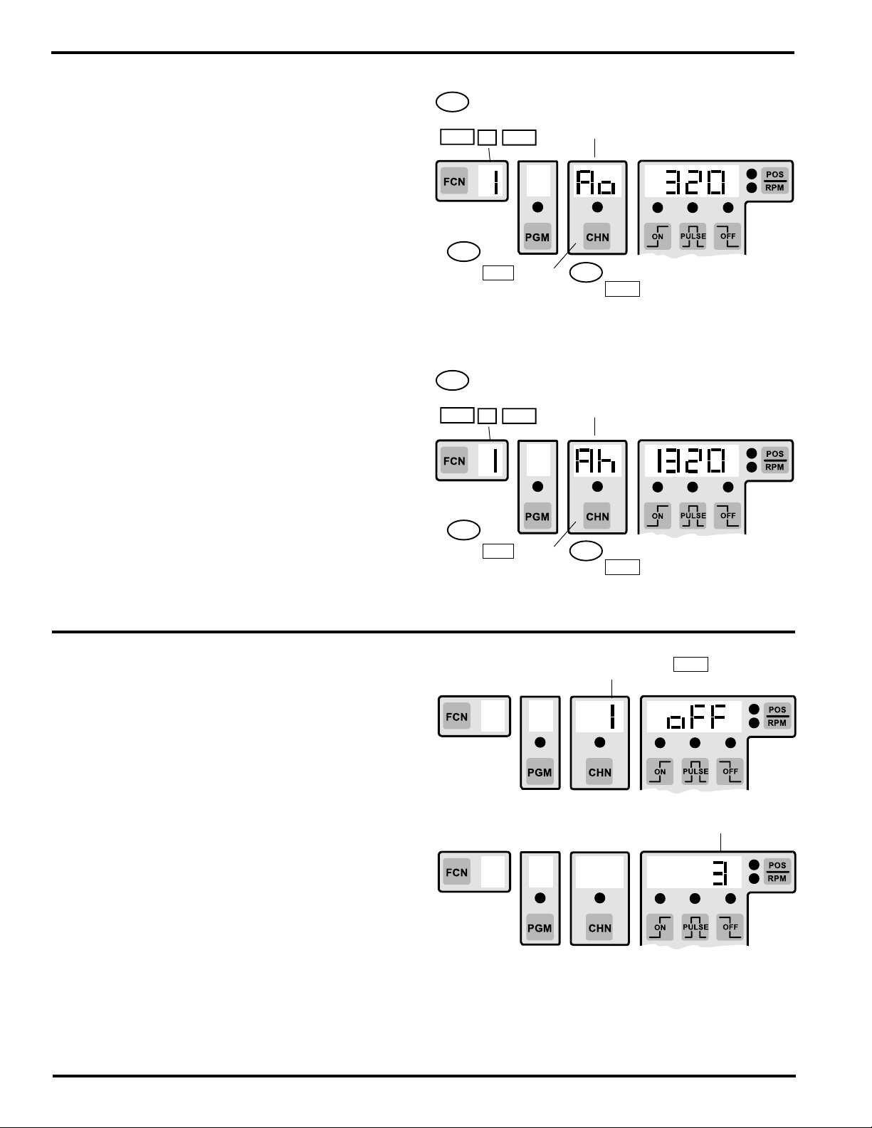
Analog Output: Option “-A”
FCN 1 Ao, Ah - Analog Output Signal
(Units with "A" option only)
The analog option allows PLµS controls to output an analog
signal that is linearly proportional to the current machine
RPM. Analog output modules are available with either 0-10
VDC or 4-20 mA output. The two parameters that define the
operation of the Analog output are the Offset and the High
RPM (speed at which full scale signal occurs).
Ao - Analog offset: The Analog offset is the analog signal
level that will be output when the machine º0is at zero RPM.
This allows the minimum analog signal to be greater than
zero volts or 4 mA, which is required in many applications.
The offset is programmed in terms of the number of 12 bit
(4096) increments that the minimum signal level should be.
Calculate the Offset value to be programmed as follows:
For 20 mA: ((Min Sig - 4) / (16)) x 4096
EX: 5 mA Min Sig Ao = ((5-4)/(16)) x 4096 = 256
For 10 VDC: (Min Sig /10) x 4096
EX: 2 VDC Min Sig Ao = (2 / 10) x 4096 = 819
Ah - Analog high RPM: The Analog high RPM is the
lowest speed at which full scale analog output will occur. It
is programmed in whole RPM.
Programming the Analog Offset
1st If FCN 1
not shown press:
FCN 1 ENT
2nd
Press CHN key
until Ao is shown
Ao - Analog
offset
3rd
Press number keys followed by
ENT key to change Analog
offset value
Present Analog offset
in 1/4096ths of full
scale signal
Programming the Analog Full Scale Signal RPM
1st If FCN 1
not shown press:
FCN 1 ENT
Ah - Analog
high (RPM)
Present RPM for full
scale analog signal
output
EX: Need 5 mA output at zero RPM and 20 mA output at
1200 RPM. Ao = 256 (mA example above) and Ah = 1200
RPM.
Outputs Based On Direction of Rotation: Option “-D”
In standard PLµS controllers without the “-D” option, outputs
will turn ON/OFF based on resolver position, regardless of
which direction the resolver is turning. With the “-D” option,
outputs can be based on the direction the resolver is
rotating. Outputs can be set individually to be based on
direction.
Direction ANDing: To choose which channels are to be
based on direction, select Alternate Function 5. This is
accomplished by pressing the FCN key and POS/RPM
key simultaneously, then pressing 5, then pressing ENTER. The number 1 will appear above the channel key
(CHN). OFF will appear in the displa y on the right, next to
the POS/RPM key.
Toggle through each channel by pressing the CHN key.
Toggle the feature between OFF, increment direction
ANDing (INC), and ON decrement (DEC) direction ANDing
by pressing the PULSE key. The factory default will be
OFF for all channels.
2nd
Press CHN key
until Ah is shown
3rd
Press number keys followed by
ENT key to change Analog
high RPM value
Channel
Use CHN key to toggle
between OFF, INC, DEC
Hysteresis value
Direction Hysteresis: Direction hysteresis is used to specify ho w many counts in one direction the resolv er must rotate
before a change in direction ANDing occurs and affects the output ON/OFF status. This level is adjustable so that
vibration in the machine will not cause outputs to switch that are direction ANDed. Select Alternate Function 6 to set this
value. A value can be entered (1 to 9999) for the number of counts that m ust pass bef ore a direction change affects the
output status. The default is 3.
5-2 Programming, Optional Features
Page 44

Speed Compensated Gray Code Output: Option “-G”
Gray Code Position Output -
( Units with the "G" Option)
Plµs Controls with the Gray Code output option output eight
bit Gray Code position information on the last eight outputs.
The position output takes into account the control's Offset
value. Therefore, the Gray Code position matches the
position shown on the control's position display. The Gray
Code position output can be Speed Compensated as a
group of outputs as shown below.
The Ladder Diagram shown on the right will convert the
eight bit Gray Code output signal (G0-G7) from the PLuS
control to a binary number (B0-B7) during each scan of the
PLC. Because only one bit changes state per Gray Code
increment, the decoding process is error free and does not
require the use of latching or handshaking circuitry. The
value of the Binary result will always be in the range of zero
to 255 because the eight bit Gray Code divides each
revolution into 256 uniform increments. Ladder rungs which
follow the conversion can compare the rotary position value
to known positions for control of machine devices that must
operate at specific positions within the overall machine
cycle. The rotary position of the machine cycle can also be
used to gate input sensors and shift register functions.
Gray Code Conversion Ladder
G7
B7
B7
B6 G5
B5
B5
B4
B4
B3
B3
B2
B2
B1
B1
G6
G6
G5B6
G4
G4
G3
G3
G2
G2
G1
G1
G0
G0
B7
B6
B5
B4
B3
B2
B1
B0
Converting Gray Code to Binary involves a sequence of
“Exclusive OR” operations. It is simple to program this same
conversion logic in other programming languages besides
ladder logic. In addition to decoding the rotary position of the
encoder, controls with arithmetic capability can be
programmed to offset position if required.
16 outputs CHN 9-16 9 = LSB, 16 = MSB
24 outputs CHN 17-24 17 = LSB, 24 = MSB
48 outputs CHN 41-48 41 = LSB, 48 = MSB
FCN 4 - Gray Code Speed Compensation
(Setup or Master program enable must be active)
Speed Compensation is the ability of the control to
automatically advance an output's setpoints as the machine
speeds up. The Gray Code position output can be Speed
Compensated as a group by entering a speed comp value
into the first channel of the Gray Code outputs (Least
Significant Bit). All of the Gray Code output channels will
be compensated by this same amount. The channels to
enter Gray Code speed comp into are as follows:
16 output system: output channel 9 (9 = LSB)
24 output system: output channel 17 (17 = LSB)
48 output system: output channel 41 (41 = LSB)
Speed compensation is set in Degrees/1000 RPM,
regardless of the scale factor being used. If the response of
the device is known, the amount of Speed Comp required
can be calculated:
Speed Comp (Deg/1000 RPM) = 6 x response (in mSec)
EX: 20 mSec response: 6 x 20 = 120 (Deg/1000 RPM
G0 - G7 = Gray Code Input Bits from PLuS
control to PLC
B0 - B7 = Binary Equivalent of Gray Code
Position from PLuS control
G0 = LSB, G7 = MSB
1st If FCN 4
not shown press:
FCN 4 ENT
2nd
Press CHN key
to select 1st Gray
Code output #
(no other Gray
Code outputs can
be selected)
1st Gray Code
Output Channel
Selected
Press number keys followed by
3rd
ENT to change Speed Comp
value
OR
DEC and INC keys can be
used to adjust Speed Comp
value in 1Deg/1000 RPM steps.
Present Speed Comp
value for Gray Code
shown
Note: 1 Degree/1000 RPM resolution allows Speed Comp
to be adjusted very accurately. However, it may be necessary to make larger changes to the Speed Comp value to
see a change in machine performance. A change of 6
degrees/1000 RPM is needed to make a 1 mSec difference
to the device being controlled.
5-3 Programming, Optional Features
Page 45

Extra Program Storage: Option “-F”
PS-5000 Series PLµS controls containing the “F” option
can store approximately four times as many output pulses
(approximately 4500 pulses) in permanent memory as
standard PS-5000 Series controls. The exact number of
pulses that can be stored will vary between different models
and features included.
An “F” option control can store as many as 992 different
setpoint programs. Unlike other PLµS controls, a special
“Pn” (program number) feature included in “F” controls
allows direct access to any program by entering its 3-digit
value. Also, the current active program number is displayed
during normal operation as shown below.
Number of Pulses/Programs Available
The actual number of different programs that can be
entered is determined by the total number of pulses that
can be stored (approx. 4500) and the number of pulses
needed for each program.
For example, if 14 outputs are being used and each output
has 1 pulse per machine cycle, the total number of programs
that could be stored would be:
4500 total pulses (approx)
14 pulses per program
= 321 programs
Special Alternate Functions have been included in the “F”
option to report the total number of pulses that can be
stored, and how many are currently programmed. See
page A-16 for directions on accessing alternate functions.
ALT FCN 1010 displays exact total number of pulses
available.
ALT FCN 1011 displays number of pulses presently
programmed.
Pulses Remaining = ALT FCN 1010 minus ALT FCN 1011
!! WARNING !!
PLµS controls continuously calculate a checksum value
which represents all of the programmed contents in the
permanent memory. The control power must remain on
a minimum of five seconds after any programming
change is made to insure that the new checksum has
been calculated.
If power is turned off before the checksum is calculated, the control will have to check the validity of all
programmed contents on the next power-up. This
will take approximately 18-20 minutes. The control
will not be able to run the machine during this time.
Active Program Number Displays
The current active program will always be displayed while
RPM is displayed as shown below.
Current Active
Program Number
(83)
NOTE: Pn shown for 2 digit Program Numbers
Current RPM
(125)
The current active program will be displayed while position
(POS) is displayed (shown below) if neither of the following
two conditions exist:
1. An output channel is selected.
2. The control is a PS-5XX4 with more than 1 output group
established.
Current Active
Program Number
(275)
NOTE: P shown for 3 digit Program Numbers
Current Position
(359)
5-4 Programming, Optional Features
(Option “-F” continued next page)
Page 46

Extra Program Storage: Option “-F” (continued)
FCN 3 - Program Number Changes
The “F” option can store up to 992 unique programs in
memory. These program numbers can be created and
accessed in random order.
A convenient Program number (Pn) feature allows the
desired program number (1-992) to be entered directly
without having to enter the corresponding values into the
Program bank (Pb) and Active Program (AP) parameters.
This is the method described below under “Changing
Program Numbers from Keyboard.”
If the hardware program select inputs are going to be used
(they can be driven from a PLC or selector switch) to select
programs, it may be necessary to program the Program
bank (Pb) and Active Program (AP) from the keyboard.
Follow the instructions given below under “Hardware
Selection of Program Number.”
Changing Active Program Number from Keyboard
Use the Program number (Pn) feature of FCN 3 to select
any program directly by entering the corresponding number
from 1-992. The corresponding “Pb” and “AP” values will
automatically be calculated and selected. It will not be
necessary to calculate or program “Pb” or “AP”, but they can
be viewed to verify that their values correspond to the
selected program number.
Viewing / Changing Program Number
1st If FCN 3
not shown press:
FCN 3 ENT
2nd
Press CHN key
to select Pn
Pn
Program
number
3rd
Press number keys followed by
ENT to change active Program
number. (1-992 are valid
Program numbers)
Present Program
number shown
Viewing / Changing the Active Program
1st If FCN 3
not shown press:
FCN 3 ENT
AP
Active
Program
Present Active Program
number shown
Pn— Program number (1-992)
Pb— Program bank (1-124); 124 banks of eight programs
each
AP— Active Program (1-8); active program within bank
Example:
If Program number (Pn) 94 is selected, “Pb” will equal 12
(12th bank of eight programs) and “AP” will equal six (6th
program within this bank).
DO NOT enter values into “Pb” or “AP” if the keyboard
program selection is being used. Simply program “Pn” to the
desired program number from 1-992.
Hardware Selection of Program Number
The hardware program select inputs override the keyboard
programmed Active Program (AP) value when any one or
combination of the inputs is energized. When the hardware
inputs are used to select the Active Program (AP), insure
that “AP” is set equal to one.
The hardware select inputs affect only the current “AP”
value that is controlling the outputs. The “Pb” is not affected
by the select inputs and has to be changed from the
keyboard if more than 8 programs are used.
Note: Active Program and Program Bank can be changed
through the serial communication port also.
2nd
Press CHN key
to select AP
3rd
Press 1 key followed by
ENT to change active Program to 1.
Viewing / Changing Program Banks
1st If FCN 3
not shown press:
FCN 3 ENT
2nd
Press CHN key
to select Pb
Pb
Program
bank
3rd
Press number keys followed by
ENT to change Program Bank
Present Program Bank
number shown
5-5 Programming, Optional Features
(Option “-F” continued next page)
Page 47

Extra Program Storage: Option “-F” (continued)
Viewing/Editing Inactive Program
Any inactive program can be viewed or edited from the
PLuS keyboard while the current active program controls
the machine.
Pressing the PGM key will select any inactive program for
viewing or editing. Press the number keys of the desired
program number followed by ENT to select the desired
inactive program. This program number will be shown in the
setpoint display area to the right of “Pn” in the channel
display (the PGM LED will be off while inactive programs
are selected).
Specify which channel, within the selected program, will be
viewed/edited by pressing the CHN key followed by the
desired channel number and ENT (the Pn display will be
replaced by the selected channel number and corresponding
output setpoint information).
To exit the selected inactive program and return to normal
active program displays press the POS/RPM key.
Select Inactive Program Number to be
Viewed/Edited
PGM LED off when
inactive program
selected
1st
Press PGM key
Pn shown
Press number keys followed by
2nd
ENT to select desired inactive
program # (1-992 are valid
program numbers)
Selected program #
shown
Select Channel to be Viewed/Edited
Selected
channel #
shown
Output setpoint data
shown for selected
program and channel
number
1st
Press CHN key
and number keys of
desired channel
Use VIEW , ON , OFF ,
2nd
PULSE , INC , DEC
and number keys to View/Edit
output setpoint data
5-6 Programming, Optional Features
Page 48
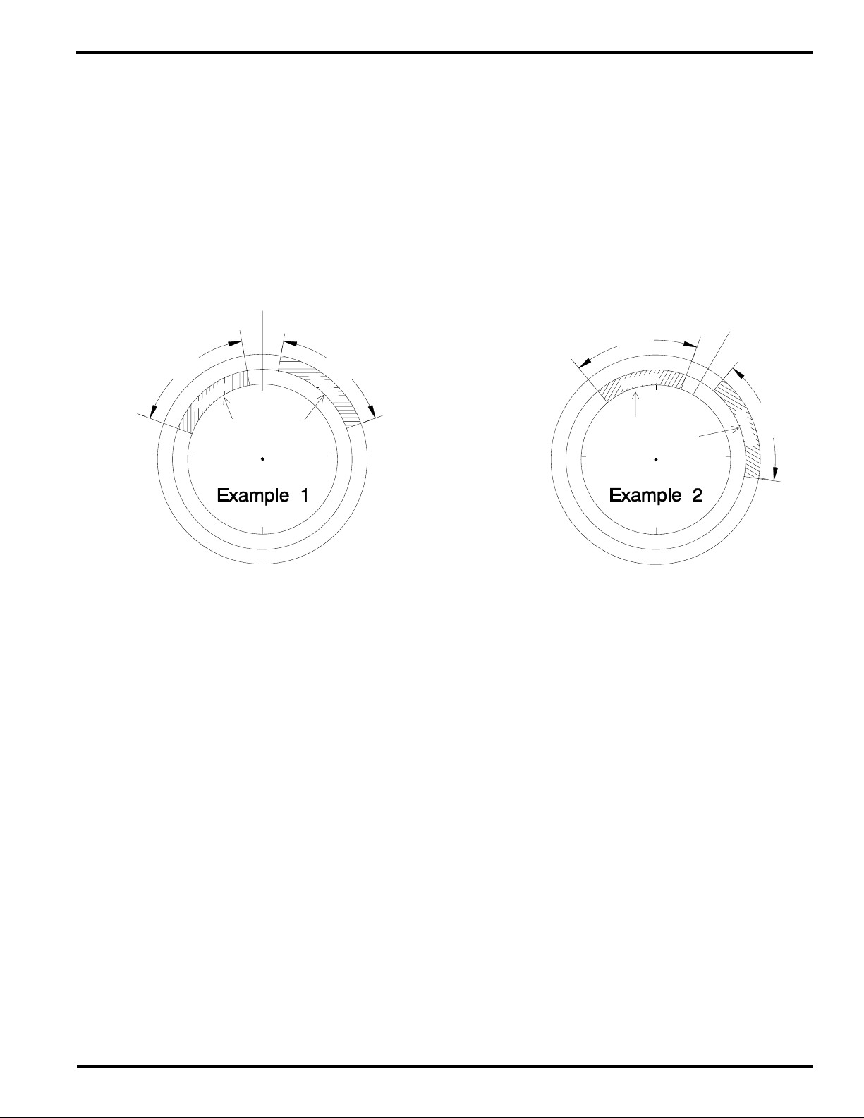
Phase Mark Registration: Option “-P”
C
H
N
1
4
C
H
N
1
5
60˚
60˚
CHN 81 = 30
(CENTER POSITION)
320
20
40
100
REG.
MARK TOO
SOON
REG.
MARK TOO
LATE
90˚
180˚
270˚
0˚
The “P” option (phase mark registration) dedicates two
PLuS outputs—Channels 14 & 15—as registration
inspection windows for input to registration controls or
PLCs. In many cases, this can replace mechanically adjusted
registration sensor mechanisms at far less cost, without
sacrificing ease of adjustment. Registration adjustments
can be made through keyboard commands or dedicated
increase and decrease hardware inputs (push buttons,
etc.).
Note: Substitute channels 7 & 8
for 14 & 15 on 9 output units.
Registration Window Examples and Adjustment Methods
CHN 81 = 0
(CENTER POSITION)
350 10
270
290
60˚ 60˚
4
1
N
H
C
REG.
MARK TOO
SOON
270˚
C
REG.
MARK TOO
LATE
H
N
1
5
70
90˚
90
Output channels 14 and 15 are programmed individually so
they have the output duration and phase relationship required
by the registration control system. Once both channels are
programmed, their setpoints can be simultaneously moved
to any machine position without altering their duration or
their phase relationship to each other. This greatly simplifies
registration setup and adjustment. Outputs 14 and 15 can
be used interchangeably as “too soon” and “too late” signals,
and their pulse durations do not have to be equal.
300
180˚
Example 1 illustrates the following:
CHN 14 - ON @ 290 OFF @ 350
CHN 15 - ON @ 10 OFF @ 70
CENTER POSITION = 0
If the registration mark is sensed while CHN 14 is on, the
registration control will determine that the material should
be retarded. If the registration mark is sensed while CHN
15 is on, the registration control will determine that the
material should be advanced. If the registration mark is
sensed between the CHN 14 and CHN 15 on pulses, the
registration is within tolerance and no adjustment is needed.
Example 2 illustrates the following:
CHN 14 - ON @ 320 OFF @ 20
Although the channel 14 and 15 values in example 2 seem
very different from example 1, they are actually the same
pulses phase shifted so that the center between them is
now 30 instead of 0. To get from example 1 to example 2,
it was NOT necessary to go into channels 14 or 15 to make
changes, only the center position had to be changed. The
pulses in outputs 14 and 15 are automatically adjusted to
correspond to the new center position.
CHN 15 - ON @ 40 OFF @ 100
CENTER POSITION = 30
5-7 Programming, Optional Features
120
The following methods change the center position:
Decrease/Increase Inputs (logic terminals 3 & 4)—
Energize the Decrease or Increase input to shift the
registration pulses and center position by one increment in
the corresponding direction (remote push buttons).
Center Input (logic terminal 5)—Energize the Center Input
on the logic input strip to change the registration center
position to the current machine position.
Channel 81—Select CHN 81 and the existing center value
will be displayed. Press INC / DEC keys or key in a new
center value and press ENT to change it.
Channel 80 - Select CHN 80 and press ENT to change the
registration center position to the current machine position
(machine was at 30 in example 2).
To accomplish registration control, it is necessary to wire
channel 14 and 15 outputs, and the registration mark
sensor, as inputs to a registration control system or PLC.
Exact wiring is determined by the control system being
used.
Some registration control systems will use the “off” portions
of channels 14 and 15 as the registration windows. The “P”
option can automatically handle these applications as well.
Detailed explanation of this "Off" logic is on page 5-13.
Page 49
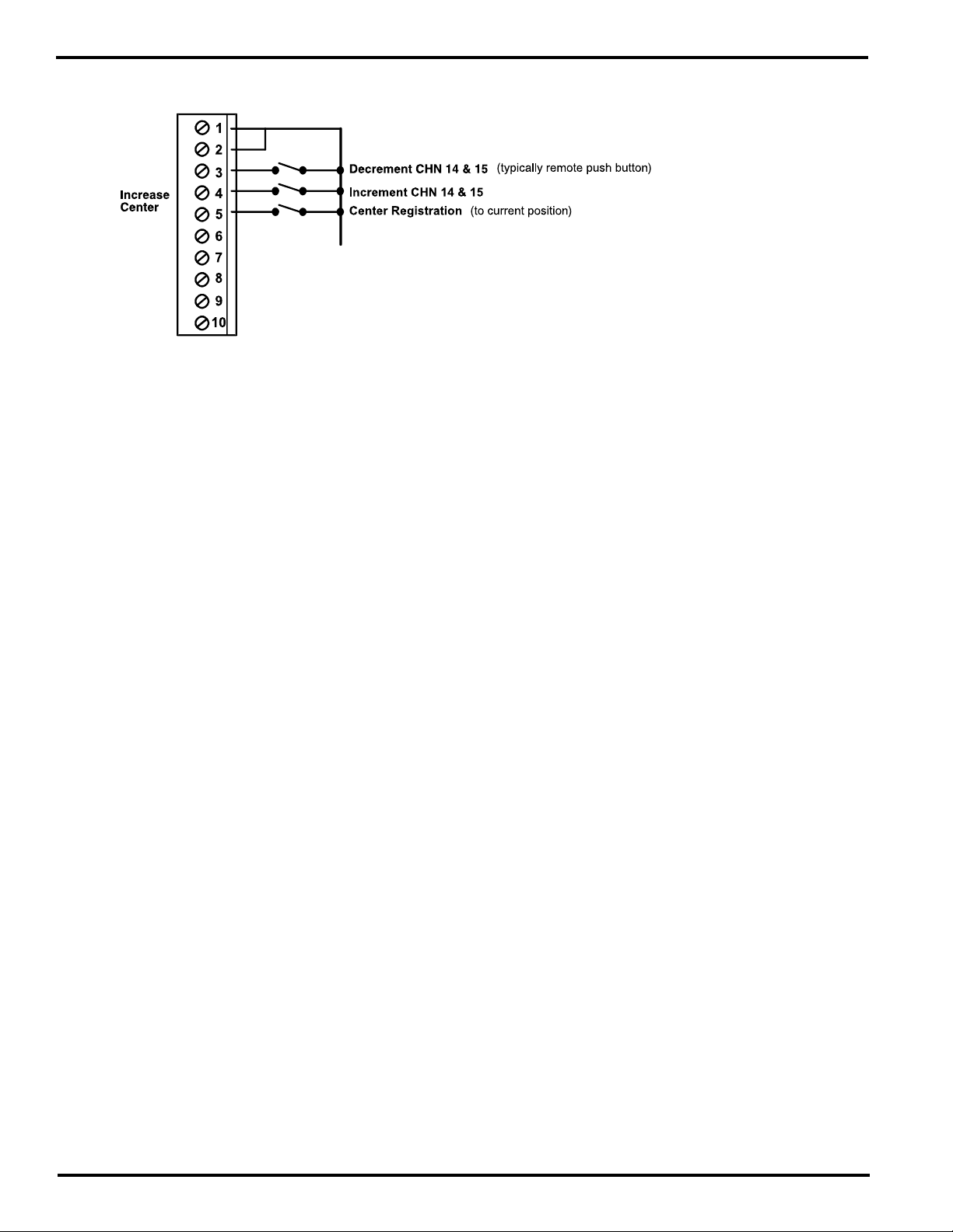
Phase Mark Registration: Option “-P” (continued)
Logic Terminal Strip (see pgs. 2-1 thru 2-3 for location)
Terminals 6 thru 10 function the same as controllers
without the “-P” Option. See pg. 3-1 for details.
Input Information
Registration Input Terminals
Input terminals 3, 4, and 5 have special registration functions
on “-P” option controls. It is not possible to use these
terminals to change programs from hardware inputs, as on
5000 Series controllers, without the “-P” option. Keyboard
program selection (FCN 3) or serial communication must be
used to change programs on “-P” option controls.
Terminals 3, 4, and 5 are always active. To program CHN
80 or CHN 81 through the keyboard, the Master, Set-Up, or
Operator access levels must be activated through the logic
terminal strip inputs or the keyboard enable codes.
General Logic Input Information
The logic inputs are energized by a current sinking path to
Logic Common. They can be switched to common through
the use of mechanical switches, relays, or NPN transistor
outputs. The inputs are held at approximately 12 VDC and
conduct 4 mA of current to common when energized.
Note: Substitute channels 7 & 8
for 14 & 15 on 9 output units.
Decrease Input (Terminal 3; normally Program Select 1)
The decrease input is a one-shot that causes the
programmed setpoints in both channels 14 and 15 to be
decremented one step each time the input is energized
(center decreases one step) . The control will display the
new CHN 14 “on” value for two seconds after the input is
energized.
Increase Input (Terminal 4; normally Program Select 2)
The increase input is a one-shot that causes the programmed
setpoints in both channels 14 and 15 to be incremented one
step each time the input is energized (center increases one
step) . The control will display the new CHN 14 “on” value
for two seconds after the input is energized.
Center Input (Terminal 5; normally Program Select 3)
The center input is a one-shot that causes the setpoints in
channels 14 and 15 to automatically change so the current
machine position becomes the registration center position.
“SEt” will be displayed for two seconds after the input is
energized (this function is equivalent to accessing CHN 80
or setting CHN 81 = current machine position).
Center Input will not function if outputs 14 and 15 do not
each have a pulse programmed.
5-8 Programming, Optional Features
(Option “-P” continued next page)
Page 50
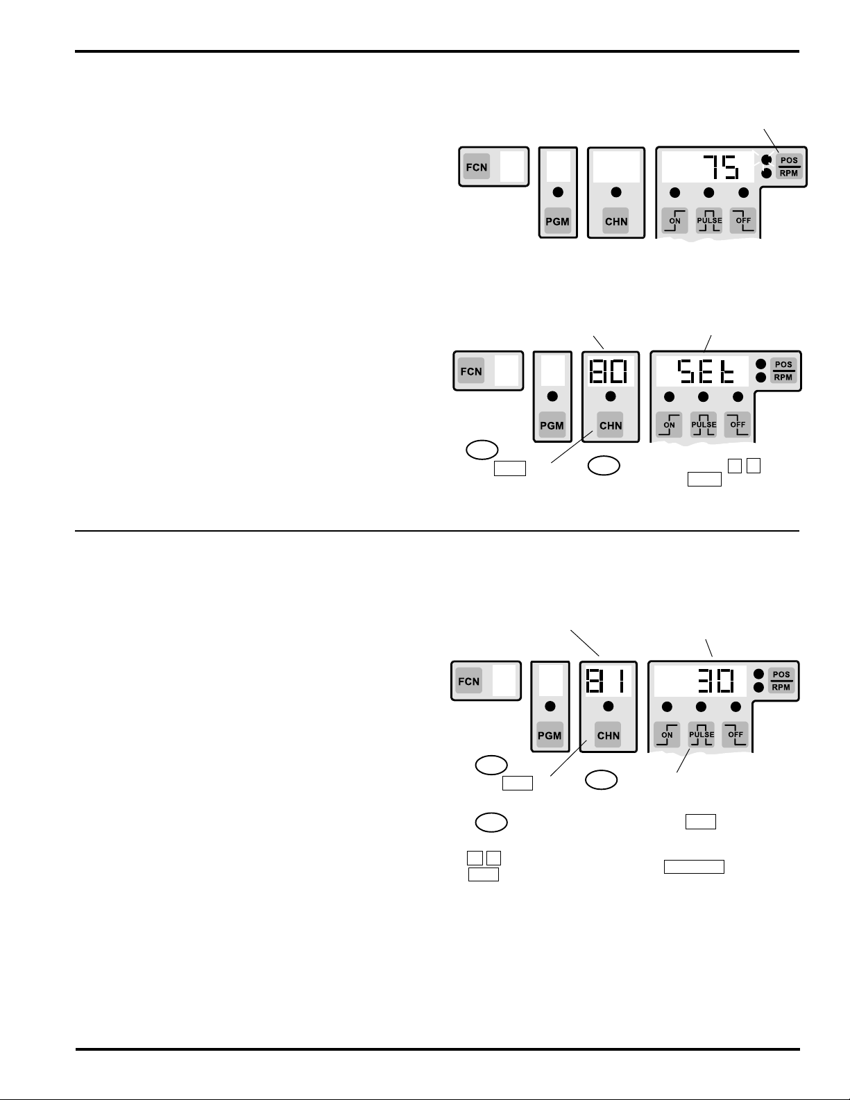
Phase Mark Registration: Option “-P” (continued)
CHN 80 - Auto-Center Registration
The gap between the output 14 and 15 pulses (registration
OK area) can be automatically centered around the current
machine position by accessing CHN 80. This allows the
correct registration phase to be set up in a single operation.
1. Move the machine (jog or move by hand) to the exact
position where the registration mark should be detected
by the sensor.
2 Access CHN 80 to center the current registration windows
around the current machine position (machine should be
stopped).
3. Display will show "SEt" after CHN 80 is entered to
confirm that the centering operation has been
accomplished.
Energizing the hardware Center Input causes the control to
perform the same operation as CHN 80.
CHN 80 or the hardware Center Input will not function
if outputs 14 and 15 do not each have a pulse
programmed.
Note: Substitute channels 7 & 8
for 14 & 15 on 9 output units.
Jog machine to position where
Registration mark should be sensed.
Press POS/RPM key until POS LED
is lit to view machine position
Access CHN 80 to center registration
around current machine position.
CHN 80 Displayed
1st
Press number keys 8 0
Press CHN key
2nd
followed by ENT to set
registration center position
"SEt" displayed to confirm
registration change made
CHN 81 - Display Adjust Registration Center
The center of the gap between the output 14 and 15 pulses
(registration OK area) can be monitored and/or changed
through CHN 81. Each time CHN 81 is accessed, its value
is calculated from the current output 14 and 15 pulses.
Therefore, CHN 81 can be a unique value within each
program and is not a global value. For this reason, CHN 81
is not part of the PLuSNET ASCII file used to store, edit and
load the control’s programmed contents through serial
communication.
Changes can be made by entering the new center position
through the keyboard, eliminating the need to move the
machine to a specific position.
1 Access CHN 81 to view the current registration center
position value.
2. Key in the new desired center position and press “Enter”
to change it; or Press “INC/DEC” keys to make one step
changes to the center position. Each time the Increase
or Decrease inputs are energized, the display will show
the new registration center position (CHN 81) for 2
seconds. If no change is desired, press “POS/RPM” to
return to the Position or RPM display, or access other
programming operations in the normal manner.
Access CHN 81 to view / change
current registration center position
CHN 81 Displayed
1st
Press CHN key
2nd
Press number keys
8 1 followed by
ENT
3rd
Current registration center
position shown
To change registration center
position PRESS number keys
of desired center position
followed by ENT
OR
PRESS INC / DEC keys to make
1 step changes to center value
CHN 81 will not function if outputs 14 and 15 do not each
have a pulse programmed.
5-9 Programming, Optional Features
(Option “-P” continued next page)
Page 51
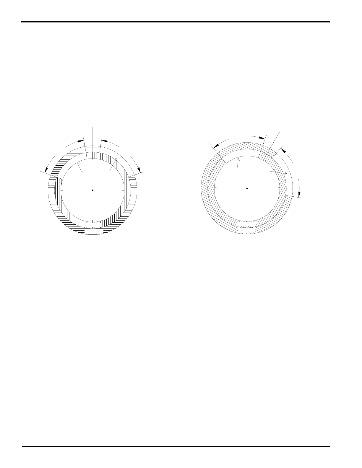
Phase Mark Registration: Option “-P” (continued)
CHN 14
60˚
60˚
CHN 81 = 30
(CENTER POSITION)
40
100
20
320
CHN 15
REG.
MARK TOO
SOON
REG.
MARK TOO
LATE
90˚
180˚
270˚
0˚
Example 4
Automatic Reversal of Centering Logic
Some registration control systems use the “Off” portion of
the input signals as the registration correction windows. In
these cases, outputs 14 and 15 will each be “On” for most
of the revolution, and off only during the registration correction
windows. The “P” option logic automatically handles these
situations.
The control assumes that “Off” registration logic is being
“OFF” Logic Registration Examples
CHN 81 = 0
(CENTER POSITION)
350
60˚ 60˚
10
used whenever the “On” duration of output 14 is greater
than 180 degrees. In this “Off” logic mode, the registration
centering functions (CHN 80, CHN 81 and the Center Input)
are based on the smaller gap between the “Off” portions of
outputs 14 and 15, rather than the smaller gap between the
“On” portions. Examples 3 and 4 below are the “Off” logic
equivalents of Examples 1 and 2 on page 5-5.
290
270˚
REG.
MARK TOO
SOON
REG.
MARK TOO
LATE
70
90˚
Example 3
180˚
N
1
4
C
H
5
H
1
N
C
CHN 14 - ON @ 350 OFF @ 290
CHN 15 - ON @ 70 OFF @ 10
CENTER POSITION = 0
In examples 3 and 4, output 14 has an on duration greater than 180. Therefore, the control automatically
assumes “off” logic is being used. All center calculations and adjustments use the smaller gap between where
outputs 14 and 15 are off.
The output 14 and 15 values in example 4 are the result of the values in example 3 being shifted by 30. CHN
80, CHN 81, and the center input can be used to adjust the center value as before. The pulses programmed
in outputs 14 and 15 are automatically adjusted to correspond to the new center position.
CHN 14 - ON @ 20 OFF @ 320
CHN 15 - ON @ 100 OFF @ 40
CENTER POSITION = 30
5-10 Programming, Optional Features
Note: Substitute channels 7 & 8
for 14 & 15 on 9 output units.
Page 52

Output Grouping and Modes
Advantages of Grouping Outputs
PS-5XX4 controls can be subdivided into as many as eight
different output groups. Each group can have dedicated
enable input. There are two primary reasons to group
outputs:
1. Outputs may be grouped together so they can be
enabled if a specific input condition is met, and disabled
if that input condition is not met.
A typical example of this situation is gluing. Usually a
photo eye or other device senses the presence of
product immediately before gluing should occur. If the
product is not present, the corresponding glue outputs
should not cycle. The controller can accomplish this type
of logic in Modes 2, 3 or 4, if these glue outputs are
grouped together and the corresponding sensor is
connected to the input which controls this group of
outputs.
2. The outputs are grouped together because they must
maintain a constant phase relationship with each other
while being able to vary their group phase relationship
to the other outputs.
A typical example of this situation is a web converting
process where individual items are being made from a
web of material. Often times the phase relationship
between different sections of the machine changes due
to stretch and other variables. The outputs at each
section must stay in phase with that section, not the
position transducer. If the outputs for a given section
are grouped, the phase of the group can be adjusted,
rather than having to individually adjust each of the
outputs in the group. The adjustments can be made
manually from the keyboard or automatically by an
external signal from a sensor or other control device.
A comprehensive understanding of the operating modes
is required to realize the potential advantages of output
grouping (pages A-3 to A-11 give detailed explanations of
each of the five modes). The fact that each group can be
in any of the five modes and operates independent of the
other groups makes grouping a powerful tool in many
applications.
Grouping Outputs and Establishing Modes
The programming of FCN 8 determines how many output
groups are created and how many outputs will be in each
group. FCN 9 programming determines how many inputs
are available and the mode in which each input (and the
corresponding group of outputs) will operate. The “Output
Group Enable 1” terminal on the logic terminal strip (p. 3-
1) is always the input for Group 1. Additional inputs require
input modules, located in the initial positions of the I/O rack.
These module positions are no longer available for outputs
and the number of outputs available is reduced accordingly.
Outputs are assigned to the groups in sequential order.
Therefore, Group 1 output(s) will start with the first available
output (after the input modules on rack) and include the
specified number of outputs. Group 2 will begin with the
next output and run sequentially until its specified number
of outputs is reached. This process continues for up to
eight groups. However, the last group will automatically
include all of the outputs that are left. Therefore, the number
of outputs in the last group is affected by the number of
outputs in the other groups and the number of additional
inputs established.
How to Program
Output Grouping and Modes
1. Access FCN 8 and program the PGM display for the
desired number of output groups. (see p. 4-9)
2. While in FCN 8 assign the desired number of outputs
to each group except the last group (it will always contain
all of the remaining outputs - this number will change if
additional inputs are specified).
3. Access FCN 9 and program the PGM display for the
desired number of inputs (see p. 4-9). Only one input
per output group is allowed. (Inputs do not have to be
allocated for groups operating in Mode 0, if these groups
come after the groups that are using other modes.)
4. While in FCN 9 specify the mode of operation for each
of the inputs established.
5. Program the appropriate input windows (CHN 91 Group 1, CHN 92 - Group 2, etc.) for groups that are
operating in Modes 1, 2 or 4. These windows must be
individually programmed in each program used.
Note: Detailed information on the operating characteristics
of modes and the function of the input windows is itemized
for each mode on pages A-3 to A-11.
Logic Input Compared to Input Modules
The input for output Group 1 is on the logic terminal strip
of the controller. Additional inputs require the use of input
modules on the I/O rack. The characteristics of each of
these input types is as follows:
Logic Terminal Input - Accepts a sinking signal only.
Does not give any indication of input status by the input
strip or on the keyboard displays. Response time is
approximately 10 msec. Does not consume an output
position on the I/O rack.
Module Input (module located on I/O rack) - AC and DC
input modules available. Typical DC response is 2-3 msec
and DC modules can be wired for sinking or sourcing
signals. An LED (in or next to module) shows input status.
Input modules are easier to interface electrically, and
provide LED indication of their on/off status. It can be
advantageous not to use the logic terminal input by
operating Group 1 in Mode 0 to control outputs not
associated with input signals.
Note: Once programmed in a channel, this function will be present in that channel in all programs.
Appendix A-1
Page 53

Output Grouping and Modes I/O Configuration Examples
Example #1: On a nine I/O 5X24, establish three groups
of outputs with four outputs in Group 1, two outputs in Group
2 and the remaining outputs (1) in Group 3. Group 2 and
Group 3 both have a photo eye input associated with them
and will operate in Mode 4.
Program FCN 8 as follows:
PGM CHN POS
3 01 4 (Group 1 = 4 outputs, modules 3-6)
3 02 2 (Group 2 = 2 outputs, modules 7-8)
3 03 1 (Group 3 = 1 output, module 9)
The “3” in the PGM display represents the number of
groups, the CHN display is the group number and the POS
display shows the number of outputs in the corresponding
group. (p. 4-7 illustrates FCN 8 programming).
Program FCN 9 as follows:
PGM CHN POS
3 E1 0 (Group 1 in Mode 0, term strip input)
3 E2 4 (Group 2 in Mode 4, module 1 input)
3 E3 4 (Group 3 in Mode 4, module 2 input)
The “3” in the PGM display represents the number of inputs
being allocated, the CHN display shows which Enable input
is being programmed, and the POS display shows the mode
selected for the corresponding input. (p. 4-7 illustrates FCN
9 programming)
Example #1: I/O Rack Configuration
Group 2
Input
Group 3
Input
Group 1
Output
Group 1
Output
Group 1
Output
Group 1
Output
Group 3
Output
Group 2
Output
M9
18
17
Group 2
Output
Note: Group 1 Input on Controller Logic Terminal Strip
(not used in this example because Group 1 is in Mode 0)
M1
M2M3M4M5M6M7M8
1
2
3
4
5
6
7
8
9
10
11
12
13
14
15
16
Example #2: On a 16 I/O 5XX4 controller, establish four
groups of outputs with six outputs in Group 1, two outputs
in Group 2, three outputs in Group 3, and the remaining
outputs (two) in Group 4. Each group requires an input
signal and the groups will operate in Modes 1-4,
respectively.
Program FCN 8 as follows:
PGM CHN POS
4 01 6 (Group 1=6 outputs, modules 4-9)
4 02 2 (Group 2=2 outputs, modules 10-11)
4 03 3 (Group 3=3 outputs, modules 12-14)
4 04 2 (Group 4=2 outputs, modules 15-16)
The “4” in the PGM display represents the number of
groups, the CHN display is the group number and the POS
display shows the number of outputs in the corresponding
group. (p. 4-7 illustrates FCN 8 programming)
Program FCN 9 as follows:
PGM CHN POS
4 E1 1 (Group 1 in Mode 1, term strip input)
4 E2 2 (Group 2 in Mode 2, module 1 input)
4 E3 3 (Group 3 in Mode 3, module 2 input)
4 E4 4 (Group 4 in Mode 4, module 3 input)
The “4” in the PGM display represents the number of inputs
being allocated, the CHN display shows which Enable input
is being programmed, and the POS display shows the mode
selected for the corresponding input. (p. 4-7 illustrates FCN
9 programming)
Example #2: I/O Rack Configuration
32
31
30
29
28
27
26
25
24
23
22
21
20
19
18
17
F16
Group 4
Output
F15
Group 4
Output
F14
Group 3
Output
F13
Group 3
Output
F12
Group 3
Output
F11
Group 2
Output
F10
Group 2
Output
F9
Group 1
Output
16
1
15
2
3
14
13
4
12
5
Group 1
6
11
10
9
Group 1
7
Group 1
8
Note: Group 1 Input on Controller Logic Terminal Strip
Group 2
Input
F1
Group 3
Input
F2
Group 4
Input
F3
Group 1
Output
F4
Output
F5
Output
F6
Output
F7
Group 1
Output
F8
F17
1
2
3
4
5
6
7
8
9
10
11
12
13
14
15
16
Appendix A-2
Page 54

Mode Introduction - Mode 0 Operation
Introduction to Modes
The use of modes allows PS-5XX4 controls to perform
output logic which goes beyond simple cam outputs. There
are five different modes (modes 0-4) which can be assigned
to output groups. Each mode has unique operating
characteristic which can be matched to the logic
requirements of the corresponding groups. In many
situations, using mode logic can eliminate the need for
external logic (PLC or discrete circuits) in series with the
PS-5XX4 outputs.
Each output group can be operated in the most appropriate
mode, regardless of which mode(s) other groups are
operating in. In many applications, more than one mode
will be used to satisfy the control requirements of different
machine sections. Following are brief descriptions of the
modes:
Mode 0 - Outputs always enabled, like a simple cam switch,
and the group position can only be adjusted manually
through the keyboard. This mode is appropriate for output
signals which must occur at the exact same position in every
machine cycle.
Mode 1 - Resets group position to zero when the group
enable input signal occurs. Outputs are always active. This
mode is appropriate for phasing output groups from sensors
or other devices which signal a mechanical reference
position. Can also be used in applications where some
machine sections run multiple cycles per resolver
revolution.
Mode 2 - Disables group outputs until the group enable
input signal occurs. When the input occurs, the group
position immediately resets to the preset value and the
outputs are allowed to cycle during the next machine cycle.
This mode is useful for applications where products may
not be evenly spaced and the group outputs must only cycle
when a product has been sensed.
Mode 3 - Only enables outputs to cycle when group enable
input is on. If the input is off, all of the outputs in the
corresponding group will be off, regardless of position. Use
this mode where the presence of a maintained signal
indicates that it is OK for the group outputs to be active.
Mode 4 - Enables outputs to cycle if the group enable input
signal turned on during a designated portion (window) of
the cycle. Outputs will be disabled at the end of the cycle
until the input signal turns on again during the window
portion of another cycle. Use this mode to check presence
and correct position of a product before enabling the output
group for this machine cycle.
Example Applications that Use Modes
Web Converting Machines - Disposable diapers, medical
pads, office folders, etc. Phase relationships between
machine sections can be adjusted manually using Mode 0
or automatically using Mode 1.
Cartoners / Case Packers - Vacuum, material handling,
loading, and other functions are usually controlled in Mode
0. Gluing functions are typically controlled in Mode 4 to
prevent glue from being dispensed when containers are
not present.
Vertical Form/Fill/Seal Machines - Package material
handling output functions are controlled in Mode 0, while
pump or fill functions are handled in Mode 1 to automatically
correct for mechanical phase changes made between these
two sections of the machine (this allows one resolver to do
a job that would otherwise require two resolvers).
Machines with Multiple Cycle Ratios - Some machines
have different sections that run at different cycle ratios per
overall machine cycle. For example, one portion of a
machine may complete several cycles while another section
makes only one cycle. By using Mode 1 or 2, it is possible
to have some output groups cycling multiple times while
other groups cycle only once.
Details of Mode 0 - Standard Cam Operation
An output group operating in Mode 0 will turn on the outputs
every time the group position is within the programmed
position setpoints. The outputs are always enabled. No input
logic is used with Mode 0; the corresponding input is
ignored. The position of the output group can only be
adjusted through the keyboard using FCN 2. The group
position information will be stored in permanent memory
and proper group position will be restored each time the
control is powered on.
Use Mode 0 whenever the corresponding outputs are
required to operate during every cycle of the machine.
How to Program Mode 0 Operation
1. Program FCN 8 and 9 to correctly establish the
output grouping and modes required for this machine
application (insure that Mode 0 is selected for this
group).
2. Check that this group has the desired position
relationship to the machine position. Program FCN 2
to adjust it.
3. Program output setpoints to cycle the outputs on and
off at the desired output group positions.
No other programming is required for Mode 0.
Note: Mode 0 logic never disables the outputs, however,
Motion ANDing (FCN 7) can disable outputs that are
operating in Mode 0.
Appendix A-3
Page 55
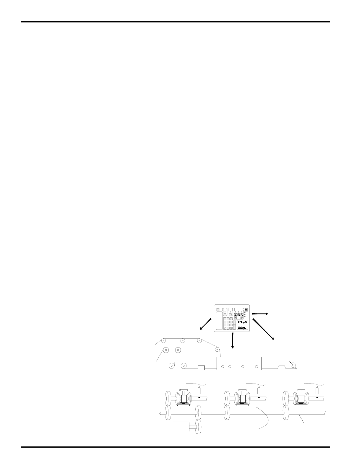
Mode 1 Operation
Details of Mode 1 -
Alter Position from Input Signal
An output group operating in Mode 1 will have its outputs
enabled at all times. What makes it different from simple
cam logic is its ability to alter its position relationship to the
machine based on an external input signal. The start
(leading edge) of an input signal will instantly cause the
group’s position to be reset to zero. The outputs will
immediately update in accordance with the zero position
and continue cycling from that point.
The input signal acts in a momentary manner, therefore it
doesn’t matter how long the input remains energized. The
reset to zero operation will occur when the leading edge of
the input signal occurs. However, once the reset occurs,
the control disarms the input and ignores it until it becomes
re-armed. A programmed window determines where the
input will become re-armed (re-arming the input is similar
to cocking a gun; once it is re-armed it can fire at any
position).
The input window is programmed in the same manner that
output pulses are programmed and is referenced to the
corresponding group position. Channel 91 is the window
for Group 1, Channel 92 for Group 2, and so on up to 98.
The position where the window is programmed determines
if the input is re-armed right away or ignored until a specified
number of degrees of travel occur. The window can be
reached from either direction of travel. Therefore, the on
edge of the window determines how much forward travel is
needed to reach the window, and the off edge determines
how much reverse travel is needed.
How to Program Mode 1 Operation
1. Program FCN 8 and FCN 9 to correctly establish
the output grouping and modes required for this
machine application (insure that Mode 1 is selected
for this group).
2. Program the input window (CHN 9X) to start where the
group enable input should be re-armed when the
machine is moving in a forward direction and to end
where the input should be re-armed if the machine is
moving in reverse. If the input should always be armed,
program CHN 9X to start on 1 and end one increment
before zero.
Note: The group input window (CHN 9X) and the group
output position setpoints must be programmed individually
for each of the controller programs used. Different programs
can have different values as required.
If the output group position fails to reset when input signals
occur, insure that an input window (CHN 9X) is programmed
and that the input is wired to the control correctly.
The position reference that is established by input signals
does not get stored in the control’s permanent memory.
Therefore, when the control powers up, a Mode 1 group
will assume the last offset programmed through FCN 2.
On power up, the input is armed and the first signal received
will cause the position to immediately reset to zero.
Example Application: Control sections of
a machine that vary in phase relationship
This illustration shows a single PLuS control
and resolver controlling three “Adjustable
Phase" sections of a converting machine. The
rotary position of the electrical output signals
can be manually set/adjusted from the
keyboard or automatically adjusted by sensors.
Each output group instantly resets it position when its input sensor energizes.
This keeps the electrical control signals properly
synchronized to the mechanical devices in each
section when phase adjustments are made.
One resolver provides the position information
needed for all sections of the machine,
regardless of their phase relationship.
Note: All gear drives are 1:1 ratio.
SECTION 1
Group 1
Input Signal
Resolver
(1:1 Ratio)
Mode 1 Example Application
FCN
0)
1)
2)
3)
4)
5)
Program
Enable Code
Motion
Detection
Offset
Active
Program
Speed
Compensation
DEG/1000 RPM
Timed
Outputs
PGM CHN
123
456
789
0
CLR
CLE
ENT
ON/OFF
SETPT
5000
Programmable Limit Switch
MOTION
POWER
CPU
Series
SECTION 2
Group 2
Input Signal
Differentials allow the
mechanical phase of each
section to be adjusted
Additional output groups can
be controlling other machine
functions in different
“Modes” as needed.
SECTION 3
Group 3
Input Signal
Line Shaft
Appendix A-4
Page 56
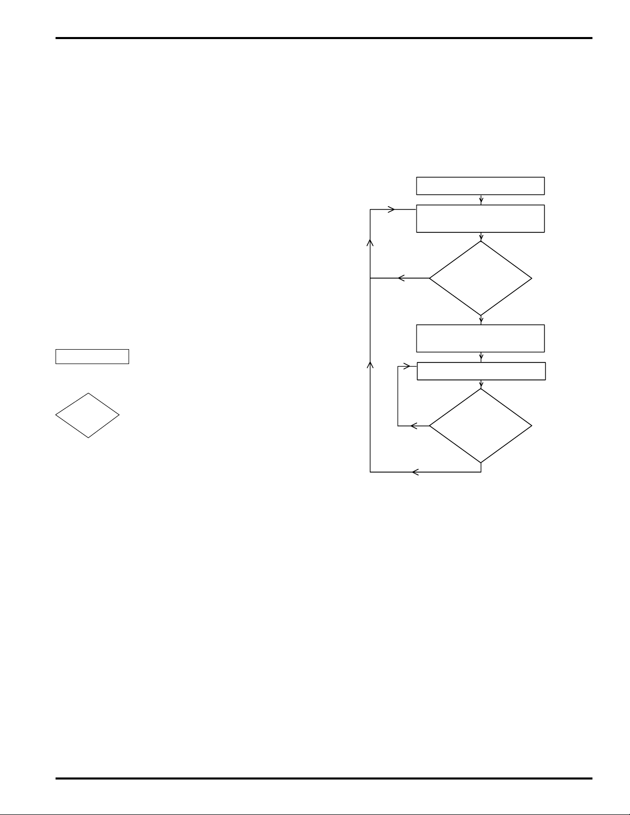
Mode 1 Logic Flow Chart
The flow chart to the right details how Mode 1 operates.
The control’s response to any set of conditions can be
determined by stepping through the flow chart blocks using
those conditions when decision blocks are encountered.
The flow chart shows when the group enable input is armed
and disarmed. Mode 1 logic never disables the outputs,
however, Motion ANDing (FCN 7) can disable outputs that
are operating in Mode 1.
Mode 1 Logic Flow Chart
How to Use the Flow Chart
To use the block diagram assume that the control is
continuously processing the blocks at a very fast rate and
is never stopped on any one block. The control will get
stuck processing the same path of blocks repeatedly (loop)
until a condition changes within one of the decision blocks
in that loop which alters the path. Response to a condition
change is almost instantaneous so the new conditions
established in the next loop take affect quickly. Note that
the logic path can only flow in the direction of the arrows,
never against them.
Rectangle Block
TASK
Output enable/disable status or a
logic memory flag is altered.
Diamond Block
A yes/no decision is made based on
DECISION
the condition stated within the block.
Mode 1 Flow Chart Blocks
1. Control powers up and assumes position determined by
last offset programmed from keyboard (FCN 2).
Power Up
Input Armed
Outputs Enabled
no
no
Input Signal
Leading Edge
Occurred?
Position Resets to zero
Input Disarmed
Outputs Enabled
Next Input
Window Reached?
yes
1
2
3
yes
4
5
6
2. Group enable input is armed. Enable the outputs to cycle
at their programmed on/off setpoints.
3. Check for leading edge of group enable input signal. If it
occurred go to step 4, if not loop back to step 2.
4. Reset group position to zero. Disarm group enable input.
5. Enable the outputs to cycle at their programmed on/off
setpoints. Go to step 6.
6. Check if group position has reached next input window
(CHN 9X). If yes go to step 2, if no loop back to step 5.
Note: Position can reach input window from forward or
reverse direction.
Appendix A-5
Page 57

Mode 2 Operation
Details of Mode 2 -
Alter Position and Enable Outputs
An output group operating in Mode 2 only has its outputs
enabled after an input signal has occurred. The start
(leading edge) of an input signal instantly causes the group’s
position to be reset to zero. The outputs will immediately
be enabled to cycle, and will stay enabled until the next
input window is reached.
The input signal acts in a momentary manner. Therefore it
doesn’t matter how long the input remains energized. The
reset operation will occur when the leading edge of the
input signal occurs. However, once the reset occurs, the
control disarms the input and ignores it until it becomes rearmed. A programmed window determines where the input
will become re-armed (re-arming the input is similar to
cocking a gun - once it is re-armed it can fire at any position).
The outputs are disabled when the next input window is
reached.
The input window is programmed in the same manner as
output pulses and is referenced to the corresponding group
position. Channel 91 is the window for Group 1, Channel
92 for Group 2, and so on up to Channel 98. The position
of the window determines where the outputs become
disabled and where the control starts looking for the next
input signal so the process can repeat. Note: If no window
is programmed, output will become active if input is
activated and will remain active.
The position reference that is established by input signals
does not get stored in the control’s permanent memory.
However, it is not important in Mode 2 since the outputs
will be disabled until an input signal occurs. On power up,
the input is armed, the outputs are disabled and the first
input signal received will cause the position to immediately
reset to zero.
How to Program Mode 2 Operation
1. Program FCN 8 and FCN 9 to correctly establish the
output grouping and modes required for this machine
application (insure that Mode 2 is selected for this group).
2. Program the input window (CHN 9X) to start at 355 and
end at 359 as initial values.
3. Manually crank or jog the machine through a cycle with
a product present. After the reset occurs (sensor detects
start of product), record the group position values where
each of the group outputs needs to cycle on or off.
Program these values into the corresponding outputs.
4. Program the input window (CHN 9X) to start before the
next valid input signal leading edge will occur. The start
of the input window must be after the latest output off
position recorded in step 4 (the start of the window
disables the outputs) and before the next input signal
leading edge. Set the end of the input window to a
position that is ahead of the earliest position where group
outputs start cycling on.
Note: The group input window (CHN 9X) and the group
output position setpoints must be programmed individually
for each of the controller programs used. Different programs
can have different values as required.
If the output group fails to operate when the machine is run
with product present, insure that the group input leading
edge occurs after the first programmed window (CHN 9X)
and that the input is wired to the control correctly.
The flow chart to the right details how Mode 2 operates.
Mode 2 Example Application
Example Application: Control different
machine functions asynchronously, on
demand
This illustration shows a PLµS control and one
resolver “independently” controlling two glue
heads at different locations on a conveyor. The
spacing between parts being glued is random.
Each output group instantly resets its control
position when its enable input energizes. The
outputs in the group then become active for up
to 359 degrees.
Random spacing between parts is automatically
handled because each sensor causes the
position of its output group to reset. This
references the output signals to the leading
edge of the part being glued. When parts are
not present the outputs will be inactive.
Additional output groups can be
controlling other machine functions
in different “modes” as needed
Group 1 Enable Input (resets
Group 1 position and activates
Group 1 outputs)
Conveyor
One resolver provides travel
information for both glue heads
Appendix A-6
Sensor
FCN
0)
Program
Enable Code
Motion
1)
Detection
2)
Offset
Active
3)
Program
Speed
4)
Compensation
DEG/1000 RPM
5)
Timed
Outputs
Group 1 Output
PGM CHN
123
456
789
DEC
ON PULSE OFF
ON/OFF
SETPT
CLR
CLE
5000
Programmabl e Limit Swit ch
ENT
INC
0
VIEWVIEW
Group 2 Output
Glue Heads
Sensor
Group 2 Enable Input (resets
Group 2 position and
activates Group 2 outputs)
POS
RPM
MOTION
POWER
CPU
Series
Glue Bead
Page 58

Mode 2 Logic Flow Chart
The control’s response to any set of conditions can be
determined by stepping through the flow chart blocks using
those conditions when decision blocks are encountered.
The flow chart determines when the outputs are enabled
and disabled by Mode 2 logic. Note: Motion ANDing (FCN
7) can also disable outputs.
How to Use the Flow Chart
To use the block diagram assume that the control is
continuously processing the blocks at a very fast rate and
is never stopped on any one block. The control will get
stuck processing the same path of blocks repeatedly (loop)
until a condition changes within one of the decision blocks
in that loop which alters the path. Response to a condition
change is almost instantaneous so the new conditions
established in the next loop take affect quickly. Note that
the logic path can only flow in the direction of the arrows,
never against them.
Rectangle Block
Output enable/disable status or a
TASK
Diamond Block
DECISION
logic memory flag is altered.
A yes/no decision is made based on
the condition stated within the block.
Mode 2 Logic Flow Chart
Power Up
Outputs Disabled
Input Armed
no
Input Signal
Leading Edge
Occurred?
yes
Position Resets to zero
Input Disarmed
Outputs Enabled
3
1
2
4
5
Mode 2 Flow Chart Blocks
1. Control powers up and assumes position determined
by last programmed offset.
2. Outputs are disabled. Group enable input is armed.
3. Check for leading edge of group enable input signal. If it
occurred go to step 4, if not loop back to step 2.
4. Reset group position to zero. Disarm group enable input.
5. Enable the outputs to cycle at their programmed on/off
setpoints. Go to step 6.
6. Check if group position has reached next input window
(CHN 9X). If yes go to step 2, if no loop back to step 5.
Note: Position can reach input window from forward or
reverse direction.
no
Next Input
Window Reached?
yes
6
Appendix A-7
Page 59
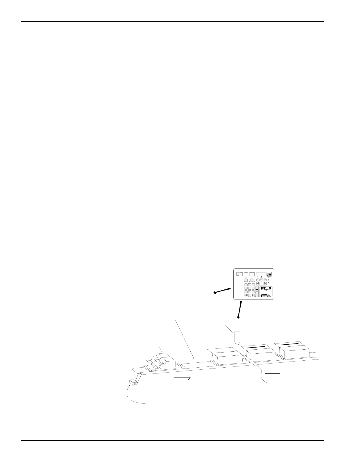
Mode 3 Operation
Details of Mode 3 -
AND Outputs with Input Signal
An output group operating in Mode 3 will have the same
characteristics as a group operating in Mode 0, except that
the corresponding enable input must be on to enable the
outputs in this group (acts like the input is in series with
each output). When the input is on the outputs will be
enabled, but as soon as the input turns off they will be
disabled. When the group position is within an output’s
setpoints, that output would turn on as soon as the input
turned on, and would turn off as soon as the input turned
off. Therefore, if the input changes state during the pulse, it
is possible to only get a partial output pulse. As in Mode 0,
position changes can only be made through FCN 2, and
position information in maintained in the control's permanent
memory.
Use Mode 3 if the group outputs can only be allowed to
cycle when a maintained enable signal is present.
How to Program Mode 3 Operation
1. Program FCN 8 and 9 to correctly establish the
output grouping and modes required for this machine
application (insure that Mode 3 is selected for this group).
2. Check that this group has the desired position
relationship to the machine position. Program FCN 2
to adjust it.
3. Program output setpoints to cycle the outputs on and
off at the desired output group positions.
No other programming is required for Mode 3 to operate. If
an output group operating in Mode 3 fails to cycle its outputs,
insure that the input signal is on and wired to the control
correctly. Motion ANDing (FCN 7) can also prevent the
outputs from cycling.
Example Application: Operate a
machine function only while a
related input signal is maintained
In this illustration the glue head will
only be allowed to operate while the
photo eye sees the top edge of a box.
Boxes that are crushed or not
properly erected will cause the glue
function to be aborted when the eye
loses sight of the top edge.
Mode 3 operation eliminates the
need to hard wire photo eyes and
other sensors in series with the
corresponding controller outputs.
Instead, the sensor input is “ANDed”
with the selected output(s) through
Mode 3 programming.
Additional output groups can be
controlling other machine
functions in different “modes” as
needed
The gluing operation will be aborted
during this empty “flight bar
The gluing operation will be
aborted during the crushed
portion of this box
Conveyor
Resolver monitors conveyor travel
Mode 3 Example Application
Glue Head
0)
1)
2)
3)
4)
5)
FCN
Program
Enable Code
Motion
Detection
Offset
Active
Program
Speed
Compensation
DEG/1000 RPM
Timed
Outputs
PGM CHN
123
456
789
0
CLR
CLE
ENT
ON/OFF
SETPT
5000
Programmable Limit Switch
MOTION
POWER
CPU
Series
Enable Sensor
(gluing will NOT
occur when this
sensor is
de-energized)
Appendix A-8
Page 60

Mode 3 Logic Flow Chart
The flow chart to the right details how Mode 3 operates.
The control’s response to any set of conditions can be
determined by stepping through the flow chart blocks using
those conditions when decision blocks are encountered.
The flow chart determines when the outputs are enabled
and disabled by Mode 3 logic. Note: Motion ANDing
(FCN 7) can also disable outputs.
How to Use the Flow Chart
To use the block diagram assume that the control is
continuously processing the blocks at a very fast rate and
is never stopped on any one block. The control will get
stuck processing the same path of blocks repeatedly (loop)
until a condition changes within one of the decision blocks
in that loop which alters the path. Response to a condition
change is almost instantaneous so the new conditions
established in the next loop take affect quickly. Note that
the logic path can only flow in the direction of the arrows,
never against them.
Mode 3 Logic Flow Chart
Power Up
Outputs Disabled
1
2
Rectangle Block
TASK
Diamond Block
DECISION
Output enable/disable status or a
logic memory flag is altered.
A yes/no decision is made based on
the condition stated within the block.
Mode 3 Flow Chart Blocks
1. Control powers up based on the last group position
reference that was programmed into FCN 2.
2. Disable outputs (do not allow them to cycle at their
programmed position setpoints).
3. Check if group enable input on. Go to step 4 if it is, loop
back to step 2 if it is not.
4. Enable outputs to cycle on and off at their programmed
position setpoints. Loop back to step 3.
no
Outputs Enabled
Group Enable
Input On?
yes
3
4
Appendix A-9
Page 61

Mode 4 Operation
Details of Mode 4 -
Input Signal Required for Output Cycle
An output group operating in Mode 4 only has its outputs
enabled after an input signal has occurred within a specified
window of the machine cycle. The start (leading edge) of
the input signal will cause the group’s outputs to be enabled
to cycle, and they will stay enabled until the next input
window is reached. The group position is not altered by the
input signal.
The input signal acts in a momentary manner, therefore, it
doesn’t matter how long the input remains energized.
However, the leading edge of the input must occur within
the programmed input window. The outputs will then
become enabled and will remain enabled until the start of
the next input window is reached.
The input window is programmed in the same manner as
output pulses and is referenced to the corresponding group
position. Channel 91 is the window for Group 1, Channel
92 for Group 2 and so on up to Channel 98. The starting
position of the window determines where the outputs
become disabled and where the control starts looking for
the next input signal so the process can repeat.
The position reference for the group is not affected by the
input signal. Therefore the group position maintains a
constant relationship with the machine position. On power
up, the group position will be based on the last position
reference that was determined by FCN 2 programming.
This reference can only be altered through FCN 2
programming from the keyboard.
Example Application: Operate
machine function(s) only if sensor
detects part in correct position
How to Program Mode 4 Operation
1. Program FCN 8 and FCN 9 to correctly establish
the output grouping and modes required for this machine
application (insure that Mode 4 is selected for this
group).
2. Check that this group has the desired position
relationship to the machine position. Program FCN 2 to
adjust it.
3. Record the starting position value where the sensor first
detects the product as it passes by (leading edge of
input).
4. Record the earliest and latest positions where one or
more outputs in this group must be on.
5. Program the input window (CHN 9X) to start before the
leading edge position of the input signal (recorded in
step 3) and end after the leading edge position. The
start of the input window must be after the latest output
position recorded in step 4 (the start of window disables
the outputs) and before the leading edge of the input
signal occurs. Set the end of the input window to the
latest position in the cycle that a valid input signal
leading edge could occur.
Note: The group input window (CHN 9X) and the group
output position setpoints must be programmed individually
for each of the controller programs used. Different programs
can have different values as required.
If the output group fails to operate when the machine is run
with product present, insure that the group input leading
edge occurs within the programmed window (CHN 9X) and
that the input is wired to the control correctly.
Note: Once programmed in a channel, this function
will be present in that channel in all programs.
In this illustration the punch will operate if
the enable sensor detects the leading
edge of the part at the correct position in
the machine cycle. The presence and
correct position of parts is verified by the
enable sensor before the group output(s)
are activated. The control position
remains in sync with the machine position.
The output(s) in the group become active
for the remainder of the machine cycle if
the enable sensor signal occurs within a
specified position in the machine cycle.
Sensor signals that occur outside of the
programmed "enable input window" will
be ignored.
This mode of operation is appropriate for
flight bar conveyors, rotary index tables
and similar types of machinery.
Additional output groups can be
controlling other machine functions
in different “modes” as needed
Empty flight bar
will
automatically be
Part too far ahead of
skipped
flight bar will be
skipped
Conveyor
Resolver monitors conveyor travel
Appendix A-10
Mode 4 Example Application
Hole Punch
Enable sensor
(activates group
outputs for 1 cycle)
FCN
0)
Program
Enable Code
1)
Motion
Detection
2)
Offset
Active
3)
Program
Speed
4)
Compensation
DEG/1000 RPM
5)
Timed
Outputs
PGM CHN
123
456
789
0
MOTION
POWER
CPU
ON/OFF
SETPT
CLR
CLE
5000
Series
Programmable Limit Switch
ENT
Activated output fires punch
when programmed output
setpoints are reached
Page 62

Mode 4 Logic Flow Chart
The flow chart to the right details how Mode 4 operates.
The control’s response to any set of conditions can be
determined by stepping through the flow chart blocks using
those conditions when decision blocks are encountered.
The flow chart determines when the outputs are enabled
and disabled by Mode 4 logic. Note: Motion ANDing (FCN
7) can also disable outputs.
How to Use the Flow Chart
To use the block diagram assume that the control is
continuously processing the blocks at a very fast rate and
is never stopped on any one block. The control will get
stuck processing the same path of blocks repeatedly (loop)
until a condition changes within one of the decision blocks
in that loop which alters the path. Response to a condition
change is almost instantaneous so the new conditions
established in the next loop take affect quickly. Note that
the logic path can only flow in the direction of the arrows,
never against them.
Mode 4 Logic Flow Chart
Power Up
Outputs Disabled
no
Group
Position within
Window?
1
2
3
Rectangle Block
TASK
Output enable/disable status or a
logic memory flag is altered.
Diamond Block
A yes/no decision is made based on
DECISION
the condition stated within the block.
Mode 4 Flow Chart Blocks
1. Control powers up based on the last group position
reference that was programmed into FCN 2.
2. Outputs are disabled.
3. Check group position within the group input window. Go
to step 4 if it is, loop back to step 2 if it is not.
4. Check for leading edge of group enable input signal. If it
occurred go to step 5, if not loop back to step 2.
5. Enable the outputs to cycle at their programmed on/off
setpoints. Go to step 6.
6. Check if group position has reached next input window
(CHN 9X). If yes go to step 2, if no loop back to step 5.
Note: Position can reach input window from forward or
reverse direction.
no
no
Input Signal
Leading Edge
Occurred?
Outputs Enabled
Next Input
Window Reached?
yes
yes
4
yes
5
6
Appendix A-11
Page 63

Error Messages
Two types of errors may be displayed:
Programming Programming error messages indicate that a programming attempt was invalid. Except for error message
“E0 EErr”, the control will continue to operate the outputs normally during programming errors.
Programming error messages will be flagged in the following list with this symbol:
System System errors occur when conditions are detected that can cause unreliable operation. All outputs will
be disabled when system error messages occur. The cause of a system error must be determined
and corrected before reliable controller operation can be guaranteed. Contact the Electro Cam factory
for assistance whenever system error messages repeat. System errors will be flagged in the following
list with this symbol:
CrASH
E0EErr
E0FAtL
Watchdog Timer Fault
The Watchdog Timer has timed out, indicating that the controller is not properly executing its program.
All outputs will be disabled during this error condition. This problem can be caused by severe electrical
noise or hardware failure within the control.
Solution: Remove and restore AC input power to the controller. If the control immediately repeats the
CrASH error condition each time it is powered up, hardware within the control is damaged. Call Electro
Cam for return authorization and further advice.
If CrASH errors occur at intermittent intervals, they are apparently being caused by excessive electrical
noise. Check wiring for proper shielding and grounding.
EEPROM Programming Error
The Checksum associated with the Function programming (controller’s global configuration) was found
to be incorrect.
Solution: Press the CLR/CLE key to clear the flashing error message. All configuration programming
(Functions) will be returned to the factory defaults, but setpoint information will remain unchanged. It will
be necessary to re-program all functions that were altered from the factory defaults. (See page A-16, Alt
Fcn 7000 for a listing of factory defaults.)
Memory Fault
A problem with random access memory has been detected and the unit cannot function properly. Memory
circuitry in the controller is not functioning properly.
Solution: Control must be returned to factory for repair. Call Electro Cam first for return authorization
and further information.
E1 CHEC
E1 OLAP
E2run
Checksum Error (Checked on Power-up)
The stored checksum value did not match the memory contents when checked on power-up. This
problem can be caused by severe electrical noise during power-up or hardware failure within the control.
Solution: Remove and restore AC input power to the controller. If the control immediately repeats the
E1 CHEC error condition each time it is powered up, hardware within the control is damaged. Call
Electro Cam for further information.
Pulse Overlap
The output pulse that was just created or adjusted overlaps or touches another pulse that already exists
in the same output channel. It was therefore not entered. Also, if one edge of a pulse is moved until it is
equal to the other edge, an “E1 OLAP” error will occur.
Solution: Press the CLR/CLE key to clear the flashing error message. Use VIEW keys to review the
setpoints that are already programmed on this channel to determine the cause of the overlap condition.
Item Can Not be Programmed While Running
While the encoder/resolver was turning, an attempt was made to change a programmed item that cannot
be changed unless the transducer is stationary. Items which cannot be changed while in motion are:
Direction of Rotation (FCN 0 - CL/CCL), Scale Factor (FCN 0 - SF), Output Grouping (FCN 8), and
Enable Inputs and Modes (FCN 9).
Solution: Press the CLR/CLE key to clear the flashing error message. Stop the machine (transducer)
while making the program change.
Appendix A-12
Page 64
Error Messages (Continued)
E4-Pro
E58888
E6-379
E7-dEF
Programming Not Enabled
A programming change was attempted when the corresponding level of programming access was not
enabled. There are three levels of programming access. See page 4-1 for details.
Solution: Press the CLR/CLE key to clear the flashing error message. Enable the appropriate level of
programming access and make the necessary changes.
Number Out of Range
A number was entered that exceeds allowable limits for the item being programmed. Some examples
are: a setpoint value that exceeds the scale factor; a channel number that exceeds the number of output
channels; an active program number that exceeds 8; etc.
Solution: Press the CLR/CLE key to clear the flashing error message. Enter a valid value for the item
being programmed.
Illegal Setpoint Value (encoder controls only)
A setpoint value with a 3, 7, or 9 in the units digit was entered into a PS-50XX (encoder based) controller.
Degree positions with 3, 7, or 9 in the units digit are skipped except for the following positions: 89, 179,
269 and 359.
Solution: Press the CLR/CLE key to clear the flashing error message. Enter a value that does not have
3, 7, or 9 in the units digit.
Too Many Enable Inputs (5xx4 models only)
An attempt was made to program more Enable Inputs (FCN 9) than there are Output Groups (FCN 8).
Solution: Press the CLR/CLE key to clear the flashing error message. Review Functions 8 and 9 to
determine the cause of the problem.
E9tdE
E10-rES
Too Many Timed Outputs
An attempt was made to program more timed outputs than are allowed. The number of timed outputs
depends on the number of outputs and the timing base selected (page 4-5.)
8, 9, and 16 output systems: 8 - 1 mSec timed outputs
4 - .5 mSec timed outputs
24 and 48 output systems: 4 - 1 mSec timed outputs
(No .5 mSec time base)
Solution: Press the CLR/CLE key to clear the flashing error message.
Resolver Fault
No resolver is connected to the controller, or one of the connections to the resolver has experienced an
intermittent or maintained open circuit condition.
Solution: Press the CLR/CLE key to clear the flashing error message, restore output operation and
verify that the control is responding correctly to resolver position changes. It is important to determine
the cause of the problem to avoid its occurrence in the future. Check that the resolver cable connector
on the back of the control is plugged in all the way and that the seven wires connected to the screw
terminals are properly secured. Also check that the resolver connecter is properly secured to the resolver.
The following resistance values can be checked at the control end of the resolver cable when it is
unplugged from the controller and plugged into the resolver. Measure the resistance between wire
pairs. Measurements will fall into one of two categories depending on age of resolver.
Wire Pair Resistance or Resistance
White/Black 15 to 25 Ohms 60 to 85 Ohms
Red/Black 20 to 40 Ohms 135 to 185 Ohms
Green/Black 20 to 40 Ohms 135 to 185 Ohms
E11-ScE
(Continued next page)
Too Many Speed Compensated Channels (48 output systems only)
An attempt was made to program more that 16 speed compensated outputs into a 48 output controller.
Solution: Press the CLR/CLE key to clear the flashing error message.
Appendix A-13
Page 65

Error Messages (Continued)
FAtL int
LinEFAiL
Pb Stuc
StoP
Internal Run Error
There is a hardware problem with internal circuitry. All outputs will be disabled.
Solution: Call Electro Cam for return authorization and further information.
Input Power Voltage Low
The input power to the controller dropped below normal operating voltage, causing the controller to stop
functioning. Check that input supply voltage to controller is within specified operating range (pg.A-18).
Solution: Control will come out of “LinEFAiL” condition when input voltage rises to normal range.
Push Button Stuck
If one of the keyboard keys is on when the unit powers up, this message will be displayed. It can indicate
that a key is shorted and always on.
Solution: If “Pb Stuc” error message remains or occurs frequently on power up, call Electro Cam for
further information.
Controller in Stop Mode
When Serial Communication Command 6 (COM_STOP) is sent to the control, it goes into an idle mode
and displays the message “StoP”. The Stop mode allows serial information to be written directly into the
control's EEPROM memory, thus allowing rapid loading of program information. The PLuSNET DLOAD
(down load) program first puts the control in the Stop mode before sending information. When the
loading process is complete it returns the control to the run mode. If the loading process is interrupted,
the control might accidentally be left in the Stop mode.
Solution: Power cycle the control to restore normal operation.
Communication Port Pin Out and RS-232 Cables
PS-5000 Series DB-9 Connector (Female)
RS-485 can be used for “Multi-Drop” communication (more than one controller connected simultaneously).
RS-232 can be connected to only one control at a time.
For standard 485 communications, pin 4 must be connected to pin 6. If pins 4 and 6 are not connected,
controller will communicate with remote display, which will interfere with standard 485 communications.
RS-232 Cable Wiring—DB-25 to DB-9*
Computer or PLC PS-5000 Series
with DB-25 DB-9
RS-232 Cable Wiring—DB-9 to DB-9*
Computer or PLC PS-5000 Series
with DB-9 DB-9
*Pins 1, 4, 6, 7, and 8 must not be connected!
Damage may result from using an off-the-shelf RS-232 communications cable.
Appendix A-14
Page 66

Encoder Position Chart / 60 Pulse Disc for Encoder Based Controls
This table shows how an encoder based PLuS control scales 256 increments into degrees. Each increment
change is equal to exactly 1/256th of a revolution (approximately 1.4 degrees) even though the position
displayed sometimes changes by 2 degrees for a 1 increment change in position (control skips 3s, 7s & 9s).
PLuS = Control Position Deg = Actual Degree Postion
PLuS Deg
0 0.0
1 1.4
2 2.8
4 4.2
5 5.6
6 7.0
8 8.4
10 9.8
11 11.3
12 12.7
14 14.1
15 15.5
16 16.9
18 18.3
20 19.7
21 21.1
22 22.5
24 23.9
25 25.3
26 26.7
28 28.1
30 29.5
31 30.9
32 32.3
34 33.8
35 35.2
36 36.6
38 38.0
40 39.4
41 40.8
42 42.2
44 43.6
45 45.0
46 46.4
48 47.8
PLuS Deg
60 59.1
61 60.5
62 61.9
64 63.3
65 64.7
66 66.1
68 67.5
70 68.9
71 70.3
72 71.7
74 73.1
75 74.5
76 75.9
78 77.3
80 78.8
81 80.2
82 81.6
84 83.0
85 84.4
86 85.8
88 87.2
89 88.6
90 90.0
91 91.4
92 92.8
94 94.2
95 95.6
96 97.0
98 98.4
100 99.8
101 101.3
102 102.7
104 104.1
105 105.5
106 106.9
108 108.3
PLuS Deg
120 119.5
121 120.9
122 122.3
124 123.8
125 125.2
126 126.6
128 128.0
130 129.4
131 130.8
132 132.2
134 133.6
135 135.0
136 136.4
138 137.8
140 139.2
141 140.6
142 142.0
144 143.4
145 144.8
156 146.3
148 147.7
150 149.1
151 150.5
152 151.9
154 153.3
155 154.7
156 156.1
158 157.5
160 158.9
161 160.3
162 161.7
164 163.1
165 164.5
166 165.9
168 167.3
PLuS Deg
180 180.0
181 181.4
182 182.8
184 184.2
185 185.6
186 187.0
188 188.4
190 189.8
191 191.3
192 192.7
194 194.1
195 195.5
196 196.9
198 198.3
200 199.7
201 201.1
202 202.5
204 203.9
205 205.3
206 206.7
208 208.1
210 209.5
211 210.9
212 212.3
214 213.8
215 215.2
216 216.6
218 218.0
220 219.4
221 220.8
222 222.2
224 223.6
225 225.0
226 226.4
228 227.8
PLuS Deg
240 239.1
241 240.5
242 241.9
244 243.3
245 244.7
246 246.1
248 247.5
250 248.9
251 250.3
252 251.7
254 253.1
255 254.5
256 255.9
258 257.3
260 258.8
261 260.2
262 261.6
264 263.0
265 264.4
266 265.8
268 267.2
269 268.6
270 270.0
271 271.4
272 272.8
274 274.2
275 275.6
276 277.0
278 278.4
280 279.8
281 281.3
282 282.7
284 284.1
285 285.5
286 286.9
288 288.3
PLuS Deg
300 299.5
301 300.9
302 302.3
304 303.8
305 305.2
306 306.6
308 308.0
310 309.4
311 310.8
312 312.2
314 313.6
315 315.0
316 316.4
318 317.8
320 319.2
321 320.6
322 322.0
324 323.4
325 324.8
326 326.3
328 327.7
330 329.1
331 330.5
332 331.9
334 333.3
335 334.7
336 336.1
338 337.5
340 338.9
341 340.3
342 341.7
344 343.1
345 344.5
346 345.9
348 347.3
50 49.2
51 50.6
52 52.0
54 53.4
55 54.8
56 56.3
58 57.7
110 109.7
111 111.1
112 112.5
114 113.9
115 115.3
116 116.7
118 118.1
170 168.8
171 170.2
172 171.6
174 173.0
175 174.4
176 175.8
178 177.2
179 178.6
60 Pulse Disc Setpoints for Encoder Based Controls
Pulse ON OFF Pulse ON OFF
1. 0 2
2. 6 10
3. 12 15
4. 18 21
5. 25 28
6. 31 34
7. 36 40
8. 42 45
9. 50 52
10. 55 58
11. 61 64
12. 66 70
13. 74 76
14. 80 82
15. 85 88
16. 90 92
17. 96 100
18. 102 105
19. 108 111
20. 115 118
21. 121 124
22. 126 130
23. 132 135
24. 140 142
25. 145 148
26. 151 154
27. 156 160
28. 164 166
29. 168 171
30. 174 176
230 229.2
231 230.6
232 232.0
234 233.4
235 234.8
236 236.3
238 237.7
Pulse ON OFF
31. 179 181
32. 185 188
33. 191 194
34. 196 200
35. 204 206
36. 210 212
37. 215 218
38. 221 224
39. 228 231
40. 234 236
41. 240 242
42. 245 248
43. 252 255
44. 258 261
45. 264 266
290 289.7
291 291.1
292 292.5
294 293.9
295 295.3
296 296.7
298 298.1
Pulse ON OFF
46. 269 271
47. 275 278
48. 281 284
49. 286 290
50. 294 296
51. 300 302
52. 305 308
53. 311 314
54. 318 321
55. 324 326
56. 330 332
57. 335 338
58. 342 345
59. 348 351
60. 354 356
350 348.8
351 350.2
352 351.6
354 353.0
355 354.4
356 355.8
358 357.2
359 358.6
Appendix A-15
Page 67

Alternate Functions - Utilities and Hardware Testing
Alternate functions test and/or display the hardware status
of the control or perform programming operations. Below is
an itemized list of each Alternate Function.
To access Alternate Functions:
1. Press FCN and POS/RPM keys simultaneously.
2. Press numeric keys of Alt Fcn desired.
3. Press ENT key.
Note: Master Program Enable must be On.
Press POS/RPM key to exit Alternate Functions
Alt Fcn 1: Displays Actual Position of Transducer
Resolver: 0-1023 (10 bits) or 0-4095 (12 bits, “H”
option)
Encoder: 0-255 (8 bits)
Alt Fcn 2: Displays On (1) Off (0) Status of Logic Inputs
Setpoint Display shows: Program Select Inputs
(term 3-5)
Master Program Enable
(term 6)
Channel Display shows: Output Group Enable 1 (term 7)
Operator Program Enable
(term 9)
Alt Fcn 3: Displays Absolute Value of the Current Offset
This is the number of increments that the control position is
leading the transducer position. Example: if Alt Fcn 3
displays a value of 90, the control will be at 90 when the
transducer is at its absolute 0 position.
Alt Fcn 4: 60 Pulse Disc
Programs a 60 pulse disc into the last channel of the current
active program.
Note: Controls with Analog (“-A”) option or Phase Mark
Registration (“-P”) option do not have this function.
Alt Fcn 1002: Keyboard Test
While each key is pressed a unique number is displayed (99
is displayed if no key is pressed). THE CONTROL MUST
BE POWER CYCLED TO EXIT THE KEYBOARD TEST.
Alt Fcn 1003: LED Display Test
All 7 segment Leds will first be turned on, then each Led
segment will be lit individually, followed by each of the
discrete Leds. The test repeats until a key is pressed.
Alt Fcn 1004: Watchdog Timer Test
Prevents controls internal “Watchdog Timer” circuit from
being reset. If Watchdog Timer is functioning properly, the
control will go into the “CrASH” mode. Press any key to
restart the control.
Alt Fcn 1005: Display Control Model Information
Function display: “L” if control has Leading/Trailing comp
Program display: Graycode output option (0=No, 1=Yes)
Channel display: Number of I/O channels
Setpoint display: Basic model number (5001, 5104, etc)
Alt Fcn 1006: Display Options and Revision #
Function display: “P” if control has Register Mark
Phasing
Program display: “A” if control has Analog
Channel display: first digit: “c” if control has Serial Comm
2nd digit: “H” if High Resolution control
Setpoint display: Software Rev # (ex: 507 = Rev 5.07)
Alt Fcn 7000: Restore Factory Defaults and Clear All
Output Channel Setpoints
Control will scroll through memory locations shown in
position display for approximately 45 seconds. “CrASH” will
be displayed when operation is completed. Press CLR/CLE
key to restore normal operation.
Factory Defaults are:
FCN 0 dr = CCL
SF = 360
P1 = 0000
P2 = 0000
Sc = onE
tb = 1
ct = 485
cS = 9600
cA = 1
dd = SPd
tr = 20
Alt Fcn 7001: Clear All Output Channel Setpoints
Control will scroll through memory locations shown in
position display for approximately 25 seconds. “7001” will
be displayed when operation is completed. Press any key
to restore normal operation.
Alt Fcn 7999: Extensive EEPROM Test
(Restores Defaults and Clears All Channel Setpoints)
Control will scroll through memory locations shown in
position display for approximately 6-1/2 minutes. “EO EErr”
will be displayed when operation is completed. This error
will show up once at the end of the test, and is not a problem
unless it occurs during normal operation. "CRASH" will be
displayed on older versions. Press CLR/CLE key to restore
normal operation.
If a problem is found with the EEPROM the display will latch
up with the bad memory location address shown. Call
Electro Cam for further information if this happens.
FCN 1 Lo = 10
Hi = 3000
Ao = 0
Ah = 2047
FCN 3 AP = 1 Pb = 1
FCN 4 All Channels 0
FCN 5 All Channels 0
FCN 6 All Channels Off
FCN 7 All Channels Off
FCN 8 1 Group, All Channels
FCN 9 1 Input, Mode 0
Appendix A-16
Page 68
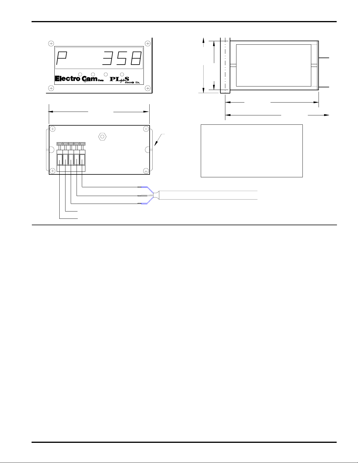
Remote Display Installation, Wiring and Setup
12345
R-
R+
T-
T+
V+
V-
SH
(Front View)
SW2
SW1
3.56"
(90.4)
SW3 SW4
Dimensioned / Wiring Drawing
1.96"
(49.8)
1.74"
(44.2)
(Side View)
Remote Display Pt#:
PS-5404-10-001
3.48"
(88.4)
3.85"
(97.8)
The remote display receives data from the PLµS control via
RS-485 serial communication. NOTE: Prior to date code
9740, the “-E” and “-C” options were required for
communications. The display will show either the
controller's present rotary position or RPM as follows:
P 3 5 9 (example of position 359 shown by remote display)
r 2 5 0 (example of 250 RPM shown by remote display)
The toggle RPM (“tr”) value programmed in FCN 0
determines the speed at which the display switches from
showing position to RPM. At speeds below the toggle RPM
value, position will be shown. At speeds equal to or above
toggle RPM, the current RPM value will be displayed. It is
not necessary for the control's display default (“dd”) to be
set to auto; the display will automatically switch between
position and RPM at the toggle RPM value, regardless of
what the control's display is showing. The value of RPM
update (“ru”) will determine how many times per second the
display updates RPM.
To display position at all times, set the toggle RPM to a
number that is higher than the maximum speed of the
machine. To display RPM at all times set the toggle RPM
to zero.
Note: A jumper between term 4 & 6 on the PLµS comm port
will disable display data to allow normal serial
communication.
(Back View)
5. Green - Signal Ground
4. Black - Data -
3. Red - Data +
115 VAC (Display Input Power)
Display Operation
Mounting
Clip
(90.4 mm x 44.2 mm)
PS-5402-03-XXX (cable assy w/DB-9 End)
(XXX = Length in Ft)
Controller / Display Setup
Setup these FCN 0 items in the PLµS control as follows:
cS = 9600 9600 baud selected for communication speed.
This is the fastest speed at which the display
will operate, and is the factory default speed
for the controller.
ct = 485 RS-485 format selected for serial port. Display
data will not be transmitted by the controller
when in the RS-232 mode.
tr = ? Select the RPM value where display switches
from showing position to RPM
All of the programmable items in the display will be correctly
set at Electro Cam before the display is shipped. This
information is stored in permanent memory in the display
and should never have to be programmed. However, if the
display does not operate when connected to the control,
check for correct display settings as follows:
1. Press SW1 & SW2 simultaneously until the message
“b_rate” is displayed for one second. The current baud
rate will appear.
2. If the current baud rate is 9600, go to Step 3. Otherwise,
press SW3 until 9600 is displayed.
3. Press SW1 to store the 9600 baud rate and return to
normal operation.
Appendix A-17
Panel Cutout
1/8 Din
3.56" w x 1.74" H
To DB-9 Connector on
Top of Controller
Controller
Display
Page 69

Controller Specifications
Electrical
24 VDC 20-30 VDC
120 VAC 50/60 Hz: 108 - 132 VAC
240 VAC 50/60 Hz: 216 - 264 VAC
Power Consumption: 35 VA
Permanent Memory: EEPROM (no battery required)
min. 100,000 write cycles
Access. Power Out: 12 VDC, 150 mA
Terminal torque: 4.5 inch-lbs.
Use copper 60/75-C wire only
Environment
Operating Temp: 0° to 50°C (32° to 122°F)
Storage Temp: -40° to 50°C (-40° to 122°F)
Operating Humidity: 95% Relative non-condensing
NEMA Rating: For use on type 1, 4, 4X or 12
enclosure
Fuses:
20-30 VDC Operation:1.25A, 250V, SB
120 VAC Operation: 0.5A, 250V, SB
240 VAC Operation: 0.25A, 250V, SB
Physical
Overal Dimensions: 8.5"W x 6.5"H x 4.5"D
Panel Cutout Size: 7.38"W x 5.38"H
Weight: 4 Lbs.
Operation
Scan Time: 250 µs to 500 µs - Higher speed
units available—consult factory
Position Resolution: 10 bits (1024 increments -
resolver, standard control)
12 bits (4096 increments -
resolver, “-H” option control)
8 bits (256 increments +/- 0.7
Deg - Gray Code encoder)
Speed
Compensation: Programmed in Deg/1000 RPM
for each output individually (24
I/O systems and higher: 16
compensated outputs maximum)
Updated 10 times per second.
Leading/trailing edge option
(update time determined by
programming, typically 5 to 10
times per sec)
Output Timeout: 0.5 or 1.0 ms time base
(accuracy: +1,-0 time increments)
Number of
Timed Outputs: 1.0 ms time base: 8 timed outputs
0.5 ms time base: 4 timed outputs
(24 and 48 I/O systems have 1.0
ms time base only - up to 4
timed outputs)
Maximum RPM: Encoder: 2000 RPM
Resolver: Up to 3000 RPM
Depending on specific model &
optional features - Higher speed
units available—consult factory
Input Responses
Program Select: 100 ms (Hardware
response + processing time)
Output Group
Enables: 1 Scan
Serial Communication (“C” Option)
Port Types: 1 RS-232 and 1 RS-422/485
Baud Rates: 4800, 9600, 19.2K, 38.4K
Note: RS-485 can be configured as a “Multi-Drop”
network.
Analog Output (“A” Option - proportional to RPM)
Output Types: 4-20 mA or 0-10 VDC
Resolution: 12 Bit Analog Hardware
(Speed is calculated in whole
RPM and will determine the
actual number of analog steps
available in any specific
applications.)
Update Time: 100 ms
Linearity: +/- 0.3% full scale @ 25°C (77°F)
Multiple Programs: 64 Prgms. on 8, 9, & 16 I/O units
48 Programs on 24 I/O units
24 Programs on 48 I/O units
Appendix A-18
Page 70

Transducer Specifications
ENCODER(S)
Operating Temp: 0° to 50°C (32° to 122°F)
Storage Temp: -40° to 50°C (-40° to 122°F)
Operating Humidity: 95% Relative non-condensing
NEMA Rating: NEMA 12 (PS-4256, 4257)
NEMA 4X (PS-4456, 4457)
Max Cable Length: 1000 Ft.
Enclosure Size: 6"W x 6"L x 4.25"H
Mounting Holes (4): 5/16" Diameter
Weight: 9 Lbs.
Shaft Diameter: .75" (double ended) with
Woodruff keyway #606
Maximum RPM: 1000 RPM (PS-4256, 4456)
2000 RPM (PS-4257, 4457)
Resolution: 8 Bits (256 increments)
Accuracy: +/-0.7°
RESOLVER(S)
Operating Temp: -40° to 125°C (-40° to 257°F)
Storage Temp: -40° to 125°C (-40° to 257°F)
Operating Humidity: 95% Relative non-condensing
NEMA Rating: NEMA 4
NEMA 4X
Maximum RPM: 3000 RPM
Max Cable Length: 1000 Ft.
Type: Single Turn - Brushless
Resolution (all): 12 Bits (4096 increments)
Linearity (standard): +/-20 arc minutes (resolver only)
(+/-30 arc minutes combined with
R/D converter in controller)
Linearity (specials): +/-3 to +/-10 arc minutes
(resolver only)
(+/-7 to +/-14 arc minutes
combined with R/D converter
in controller)
Note: A resolver's linearity errors are repeatable at all
positions of its 360 degree rotation. Therefore, once
appropriate setpoints are established, machine performance
is consistent every cycle.
Appendix A-19
Page 71

AC/DC Output Module Specifications
AC Outputs: EC-OAC5A-11 (Standard)
EC-OAC240-3 (Slimline)
Load Voltage: 24 V rms minimum
280 V rms maximum
Load Current: 30 mA rms minimum
3A rms max.@/below 35°C (95°F)
Above 35°C derate 50 mA/°C
(27.8 mA/°F)
Input Voltage: 5 VDC nominal
8 VDC maximum
Turn On Time: 100 µs maximum @ 60 Hz
Turn Off Time: 8.3 ms maximum @ 60 Hz
Off State Leakage: 2 mA AC rms @ 120 VAC rms,
60 Hz
Frequency: 65 Hz maximum
On State Volt. Drop: 1.6 V peak maximum
Dropout Voltage: 1 VDC maximum
Pickup Voltage: 2.5 VDC minimum
Operating Temp: -30 to +70°C (-22° to +158°F)
DC Outputs: EC-ODC5 (Standard)
EC-ODC060-3 (Slimline)
Output Voltage: 0 to 60 VDC
Output Current: 3 A @/below 35°C (95°F)
Derate 35.7 mA/°C above 35°C
(19.8 mA/°F above 95°F)
Input Voltage: 5 VDC nominal
8 VDC maximum
Turn On Time: 50 µs maximum
Turn Off Time: 50 µs maximum
Off State Leakage: 1 µA DC maximum @ 24 VDC
Output Voltage Drop: 1.6 V peak maximum
Dropout Voltage: 1 VDC maximum
Pickup Voltage: 2.5 VDC minimum
Operating Temp: -30 to +70°C (-22° to +158°F)
Reed Relays: EC-ORR5 (Standard)
Output Type: N/O Reed Relay Contacts
Contact Rating: 10VA maximum
(DC resistive load)
Switching Volts: 0 V to 200 V, DC or peak AC
Switch Current: 0.5 A maximum, DC or peak AC
(resistive loads only)
Carry Current: 1.0 A maximum, DC or peak AC
Turn On Time: 1 ms
Turn Off Time: 500 µs
Mechanical Life: 50 million cycles min at rated load
Operating Temp: -30 to +70°C (-22° to +158°F)
Reed Relays: EC-ORR000-0 (Slimline)
Output Type: N/O Reed Relay Contacts
Contact Rating: 10 VA maximum
Switching Voltage: 100 VDC or 130 VAC maximum
Switching Current: 0.5 A maximum
Carry Current: 1.5 A maximum
Turn On Time: 500 ms
Turn Off Time: 500 µs
Mechanical Life: 5 x 10⁶ cycles
Operating Temp: -30 to +70°C (-22° to +158°F)
DC Outputs: EC-ODC5A (Standard)
EC-ODC200-1 (Slimline)
Output Voltage: 0 to 200 VDC
Output Current: 1 A @/below 45°C (113°F)
Derate 18 mA/°C above 45°C
(10 mA/°F above 113°F)
Input Voltage: 5 VDC nominal
8 VDC maximum
Turn On: 50 µs maximum
Turn Off: 50 µs maximum
Off State Leakage: 1 µA DC maximum @ 24 VDC
Output Voltage Drop: 1.75 VDC maximum
Dropout Voltage: 1 VDC maximum
Pickup Voltage: 2.5 VDC minimum
Operating Temp: -30 to +70°C (-22° to +158°F)
Appendix A-20
Page 72

Analog Output Module Specifications
0-10 VDC: EC-ANLG-010V (Standard)
EC-SANL-010V (Slimline)
Resolution: 12 Bits (4096 increments)
Output Voltage: 0-10 VDC
Output Current: 140 mA DC maximum
Accuracy: +/- 0.3% full scale @ 25°C (77°F)
4-20 mA: EC-ANLG-420M (Standard)
EC-SANL-420M (Slimline)
Resolution: 12 Bits (4096 increments)
Output Current: 4 mA DC to 20 mA DC
Load Resistance: 450 Ohms maximum
Accuracy: +/- 0.3% full scale @ 25°C (77°F)
Appendix A-21
Page 73

Input Module Specifications
DC Inputs: EC-IDC5 (Standard)
EC-IDC032 (Slimline)
Input Voltage: 10-32 VDC
Input Current: 34 mA maximum (@32 VDC input)
Output Supply
Voltage: 4.5 VDC to 6 VDC
5 VDC nominal
Output Supply
Current: 18 mA DC maximum @ 5 VDC
Turn On Time: 5 ms maximum
Turn Off Time: 5 ms maximum
Dropout Voltage: 2 VDC maximum
Pickup Voltage: 3 VDC minimum
Operating Temp: -30 to +70°C (-22° to +158°F)
AC Inputs: EC-IAC5 (Standard)
EC-IAC120 (Slimline)
Input Voltage: 90-140 VAC rms
Input Current: 11 mA AC rms maximum
(@140 VAC rms input)
Output Supply
Voltage: 4.5 VDC to 6 VDC
5 VDC nominal
Output Supply
Current: 16 mA DC maximum @ 5 VDC
Off State Leakage: 100 µA DC maximum @ 30 VDC
Output Voltage Drop: 0.4 VDC @ 50 mA DC
Output Current: 50 mA DC maximum
Turn On Time: 20 ms typical
Turn Off Time: 20 ms typical
Input Allowed
for No Output: 45 VAC rms,
3 mA AC rms maximum
Operating Temp: -30 to +70°C (-22° to +158°F)
AC Inputs: EC-IAC5A (Standard)
EC-IAC240 (Slimline)
Input Voltage: 180-280 VAC rms
Input Current: 5 mA AC rms maximum
(@280 VAC rms input)
Output Supply
Voltage: 4.5 VDC to 6 VDC
5 VDC nominal
Output Supply
Current: 16 mA DC maximum @ 5 VDC
Off State Leakage: 100 µA maximum @ 30 VDC
Output Voltage Drop: 0.4 VDC @ 50 mA DC
Output Current: 50 mA DC maximum
Turn On Time: 20 ms typical
Turn Off Time: 20 ms typical
Input Allowed
for No Output: 45 VAC rms,
1 mA AC rms maximum
Operating Temp: -30 to +70°C (-22° to +158°F)
Appendix A-22
Page 74

Transistor Output Specifications
Sinking Transistor Outputs (PS-5X11, N08 and N16)
Output Type: Current Sinking (NPN)
Output Voltage: 5 - 30 VDC
Output Current: 50 mA cont. maximum
Input Voltage: 5 - 30 VDC
Sourcing Transistor Outputs (PS-5X11, P08 and P16)
Output Type: Current Sourcing (PNP)
Output Voltage: 5 - 30 VDC
Output Current: 50 mA cont. maximum
Input Voltage: 5 - 30 VDC
Appendix A-23
Page 75

Index
+12 VDC Output (Logic Terminal Strip) . . . . . . . . . . 3-1
60 Pulse Disc
ALT FCN 4: Create 60 Pulse Disc . . . . . . . . . . . A-16
Output Setpoints (Encoder) . . . . . . . . . . . . . . . . A-15
Absolute Offset (ALT FCN 3) . . . . . . . . . . . . . . . . . A-16
Active Program
Standard Controllers . . . . . . . . . . . . . . . . . 3-1, 4-10
Operator Access on/oFF . . . . . . . . . . . . . . . . . . . 4-7
Option “-F”, Extra Program Storage . . . . . . . . . . . 5-4
Access Levels . . . . . . . . . . . . . . . . . . . . . . . . . . . . . . 4-1
Ah (FCN 1)—See Analog Output
Alternate Functions . . . . . . . . . . . . . . . . . . . . . . . . . A-16
ALT FCN 1: Display Transducer Position
ALT FCN 2: Display Input Status
ALT FCN 3: Display Absolute Offset
ALT FCN 4: Create 60 Pulse Disc
ALT FCN 1002: Keyboard Key Test
ALT FCN 1003: LED Display Test
ALT FCN 1004: Watchdog Timer Test
ALT FCN 1005: Display Control Model Info
ALT FCN 1006: Display Options and Rev #
ALT FCN 7000: Restore Factory Defaults
ALT FCN 7001: Clear All Channel Setpoints
ALT FCN 7999: Extensive EEPROM Test
Analog Output, Option “-A“ . . . . . . . . . . . . . . . . 1-2, 5-2
Ah, Analog High RPM . . . . . . . . . . . . . . . . . . . . . 5-2
Ao, Analog Offset . . . . . . . . . . . . . . . . . . . . . . . . . 5-2
Analog Output Module Information . . . . . . . . . . A-21
Analog Output Module Wiring . . . . . . . . . . . . . . . 3-4
Module Mounting Position . . . . . . . . . . . . . . . . . . . . .
External 16 Standard Module Rack . . . . . . . . . 3-2
External M16 Slimline Module Rack . . . . . . . . 3-2
External 24 & 48 Standard Module Racks . . . 3-3
Slimline Modules on Controller Back . . . . . . . . 3-4
ANDing
Input ANDing (Mode 3) . . . . . . . . . . . . . . . . . . . . A-8
Motion ANDing (FCN 7) . . . . . . . . . . . . . . . . . . . . 4-8
Ao (FCN 1)—See Analog Output
AP (FCN 3)—See Active Program
Auto (FCN 0) . . . . . . . . . . . . . . . . . . . . . . . . . . . . . . . 4-5
Back View of Controller . . . . . . . . . . . . 1-3, 2-1, 2-2, 2-3
botH (FCN 0) . . . . . . . . . . . . . . . . . . . . . . . . . . . . . . . 5-1
cA (FCN 0)—See Communications
Cables
Communication . . . . . . . . . . . . . . . . . . . . . . . . . A-14
Encoder . . . . . . . . . . . . . . . . . . . . . . . . . . . . . . . 3-16
Resolver . . . . . . . . . . . . . . . . . . . . . . . . . . . . . . . 3-14
ccL (FCN 0) . . . . . . . . . . . . . . . . . . . . . . . . . . . . . . . . 4-4
CHN Key . . . . . . . . . . . . . . . . . . . . . . . . . . . . . . . . . . 4-2
CHN 14, 15, 80, 81 (Option “P”) . . . . . . . . . . . . . . . . 5-7
cL (FCN 0) . . . . . . . . . . . . . . . . . . . . . . . . . . . . . . . . . 4-4
CLR/CLE Key . . . . . . . . . . . . . . . . . . . . . . . . . . . . . . 4-2
Communications . . . . . . . . . . . . . . . . . . . . . . . . . . . . 4-6
cA, Communication Address . . . . . . . . . . . . . . . . 4-6
cS, Communication Speed . . . . . . . . . . . . . . . . . . 4-6
cT, Communication Type (RS-232, -485) . . . . . . 4-6
Ports . . . . . . . . . . . . . . . . . . . . . . . . . . . . . . . . . . A-14
Wiring . . . . . . . . . . . . . . . . . . . . . . . . . . . . . . . . . A-14
Controller
Cut-out . . . . . . . . . . . . . . . . . . . . . . . . . . 2-1, 2-2, 2-3
Back View (Component Identification) . . 2-1, 2-2, 2-3
Front View (Keyboard) . . . . . . . . . . . . . . . . . . . . . 4-2
Specifications . . . . . . . . . . . . . . . . . . . . . . . . . . . A-18
CrASH (SYS Error Message) . . . . . . . . . . . . . . . . . A-12
CPU LED . . . . . . . . . . . . . . . . . . . . . . . . . . . . . . . . . . 4-2
cS (FCN 0)—See Communications
cT (FCN 0)—See Communications
"-D" Option . . . . . . . . . . . . . . . . . . . . . . . . . . . . . . . . 5-2
DEC Key . . . . . . . . . . . . . . . . . . . . . . . . . . . . . . . . . . 4-2
Default Settings . . . . . . . . . . . . . . . . . . . . . . . . . . . . A-16
Deg / 1000 RPM (See Speed Compensation)
Direction of Rotation (FCN 0 dr) . . . . . . . . . . . . . . . . 4-4
Direction of Rotation, Outputs Based on Resolver . . 5-2
Display Default (FCN 0 dd) . . . . . . . . . . . . . . . . . . . 4-5
Display, Remote . . . . . . . . . . . . . . . . . . . . . . . . . . . A-17
dd (FCN 0) . . . . . . . . . . . . . . . . . . . . . . . . . . . . . . . . 4-5
dr (FCN 0) . . . . . . . . . . . . . . . . . . . . . . . . . . . . . . . . . 4-4
E0 EErr (PGM Error Message) . . . . . . . . . . . . . . . . A-12
E0 FAtL (SYS Error Message) . . . . . . . . . . . . . . . . A-12
E1 CHEC (SYS Error Message) . . . . . . . . . . . . . . . A-12
E1 OLAP (PGM Error Message) . . . . . . . . . . . . . . . A-12
E2 run (PGM Error Message) . . . . . . . . . . . . . . . . . A-12
E4 -Pro (PGM Error Message) . . . . . . . . . . . . . . . . A-13
E5 8888 (PGM Error Message) . . . . . . . . . . . . . . . . A-13
E6 -379 (PGM Error Message) . . . . . . . . . . . . . . . . A-13
E7 -dEF (PGM Error Message) . . . . . . . . . . . . . . . . A-13
E9 tdE (PGM Error Message) . . . . . . . . . . . . . . . . . A-13
E10 -rES (SYS Error Message) . . . . . . . . . . . . . . . A-13
E11 -ScE (PGM Error Message) . . . . . . . . . . . . . . . A-13
Enable Inputs
Output Group Enable 1 (Re-Zero Input) . . . . . . . . 3-1
Program Enable . . . . . . . . . . . . . . . . . . . . . . 3-1, 4-1
Enable Codes, P1 & P2 (FCN 1) . . . . . . . . . . . . . . . . 4-4
Encoder
Cable Installation . . . . . . . . . . . . . . . . . . . . . . . . 3-16
Position Chart . . . . . . . . . . . . . . . . . . . . . . . . . . . A-15
ENT Key . . . . . . . . . . . . . . . . . . . . . . . . . . . . . . . . . . 4-2
Error Messages (Flashing)
Programming . . . . . . . . . . . . . . . . . . 4-3, A-12, A-13
System . . . . . . . . . . . . . . . . . . . . . . A-12, A-13, A-14
Factory Default Settings (Functions) . . . . . . . . . . . . A-16
FATL_int (SYS Error Message) . . . . . . . . . . . . . . . A-14
FCN Key . . . . . . . . . . . . . . . . . . . . . . . . . . . . . . . . . . 4-2
Index I-1
Page 76

Index
FCN 0
All Controllers
Direction of Increasing Rotation (dr) . . . . . . . . 4-4
Display Default (dd) . . . . . . . . . . . . . . . . . . . . . 4-5
Enable Codes (P1 & P2) . . . . . . . . . . . . . . . . . 4-4
Factor (SF) . . . . . . . . . . . . . . . . . . . . . . . . . . . 4-4
Time Base (tb) . . . . . . . . . . . . . . . . . . . . . . . . . 4-5
Toggle RPM (tr) . . . . . . . . . . . . . . . . . . . . . . . . 4-5
Communications
Communication Address (cA) . . . . . . . . . . . . . 4-6
Communication Speed (cS) . . . . . . . . . . . . . . 4-6
Communication Type (ct) . . . . . . . . . . . . . . . . 4-6
Expanded Operator Access
RPM Update Frequency (rU) . . . . . . . . . . . . . . 4-6
Option “-L”, Leading/Trailing Edge Speed Comp
Standard Speed Comp (onE) . . . . . . . . . . . . . 5-1
Leading/Trailing Edge Speed Comp (botH) . . 5-1
FCN 1
All Controllers—Motion Detection Setpoints
Lo -Low RPM Value for Speed Range . . . . . 4-10
Hi -High RPM Value for Speed Range . . . . . 4-10
Option “-A”, Analog Output
Ao -Analog Offset . . . . . . . . . . . . . . . . . . . . . . 5-2
AH -Analog High RPM Value . . . . . . . . . . . . . 5-2
FCN 2: Offset (position) . . . . . . . . . . . . . . . . . . . . . 4-10
FCN 3: Active Program
Active Program (AP) . . . . . . . . . . . . . . . . . . . 4-11
Program Bank (pB) . . . . . . . . . . . . . . . . . . . . 4-11
Program Number (pN) . . . . . . . . . . . . . . . . . . 4-11
Option “-F”, Extra Program Storage
Active Program (AP) . . . . . . . . . . . . . . . . . . . . 5-5
Program Bank (pB) . . . . . . . . . . . . . . . . . . . . . 5-5
Program Number (pN) . . . . . . . . . . . . . . . . . . . 5-5
FCN 4: Speed Compensation
Standard Controllers
Standard Speed Comp . . . . . . . . . . . . . . . . . 4-12
Negative Speed Comp (Input Gating) . . . . . . 4-12
Option “-L”, Leading/Trailing Edge Speed Comp
onE . . . . . . . . . . . . . . . . . . . . . . . . . . . . . . . . . 5-1
botH . . . . . . . . . . . . . . . . . . . . . . . . . . . . . . . . . 5-1
Option “-G”, Gray Code Speed Comp . . . . . . . . . 5-3
FCN 5: Timed Outputs . . . . . . . . . . . . . . . . . . . . . . 4-13
Operator Access on/oFF . . . . . . . . . . . . . . . . . . . 4-7
FCN 6: Operator Output Channels
Standard Controllers
Operator Can Adjust (on) . . . . . . . . . . . . . . . . 4-7
Operator Cannot Adjust (oFF) . . . . . . . . . . . . . 4-7
Active Program On/Off (AP) . . . . . . . . . . . . . . 4-7
Offset On/Off (oF) . . . . . . . . . . . . . . . . . . . . . . 4-7
Speed Comp On/Off (Sc) . . . . . . . . . . . . . . . . 4-7
Speed Detection On/Off (Sd) . . . . . . . . . . . . . 4-7
Setpoints On/Off (SP) . . . . . . . . . . . . . . . . . . . 4-7
Timed Outputs On/Off . . . . . . . . . . . . . . . . . . . 4-7
FCN 7: Motion ANDed Channels . . . . . . . . . . . . . . . 4-8
FCN 8: Output Grouping . . . . . . . . . . . . . . . . . . . . . . 4-9
FCN 9: Output Enable Modes . . . . . . . . . . . . . . . . . . 4-9
Flashing Error Messages . . . . . . .4-3, A-12, A-13, A-14
Fuses
12 VDC Power Supply (Logic Terminal Strip) . . . 3-1
Controller Input Power (1/2 Amp) . . . . . . 2-1, 2-2, 2-3
Logic Terminal Strip (12 VDC Power Supply) . . . 3-1
Rack, 16 Standard Modules . . . . . . . . . . . . . . . . . 3-2
Rack, 16 Slimline Modules (M16 Rack) . . . . . . . . 3-2
Rack, 24 & 48 Standard Modules . . . . . . . . . . . . 3-3
Slimline Modules on Controller Back . . . . . . . . . . 3-4
Transistor Outputs . . . . . . . . . . . . . . . . . . . . . . . . 3-7
Gray Code Output, Option “-G” . . . . . . . . . . . . . 1-2, 5-3
Group 1 Output Enable (Re-Zero Input) . . . . . . . . . . 3-1
(on 5XX4 models see Modes 1 & 2)
High Resolution, Option “-H” . . . . . . . . . . . . . . . . . . . 1-2
"Hi" (FCN 1), Motion Setpoints . . . . . . . . . . . . . . . . 4-10
INC Key . . . . . . . . . . . . . . . . . . . . . . . . . . . . . . . . . . . 4-2
Input Gating (Negative Speed Comp) . . . . . . . . . . . 4-12
Input Modules
Specifications . . . . . . . . . . . . . . . . . . . . . . . . . . . A-22
Wiring . . . . . . . . . . . . . . . . . . . . . . . . . . . . . . . . . . 3-5
Input Power Wiring . . . . . . . . . . . . . . . . . . . 2-1, 2-2, 2-3
Input Sensor, 3-Wire . . . . . . . . . . . . . . . . . . . . . . . . . 3-5
Inputs (Logic Terminal Strip) . . . . . . . . . . . . . . . . . . . 3-1
Keyboard . . . . . . . . . . . . . . . . . . . . . . . . . . . . . . . . . . 4-2
Displays . . . . . . . . . . . . . . . . . . . . . . . . . . . . . . . . 4-2
Enable Codes . . . . . . . . . . . . . . . . . . . . . . . . 4-1, 4-4
Hardware Test Functions . . . . . . . . . . . . . . . . . . A-16
Keys . . . . . . . . . . . . . . . . . . . . . . . . . . . . . . . . . . . 4-2
LEDs . . . . . . . . . . . . . . . . . . . . . . . . . . . . . . . . . . 4-2
Leading/Trailing Speed Comp (Option “-L”) . . . . . . . 5-1
Levels of Programming Access . . . . . . . . . . . . . 4-1, 4-8
LinEFAiL (SYS Error Message) . . . . . . . . . . . . . . . A-14
Lo (FCN 1) . . . . . . . . . . . . . . . . . . . . . . . . . . . . . . . 4-10
Logic Common (Logic Terminal Strip) . . . . . . . . . . . . 3-1
Logic Terminal Strip (Inputs) . . . . . . . . . . . . . . . . . . . 3-1
Master Level Programming Access . . . . . . . . . . . . . 4-1
Master Program Enable Input . . . . . . . . . . . . . . . . . . 3-1
Modes of Operation
Input Programming (FCN 9) . . . . . . . . . 4-9, A-1, A-2
Introduction . . . . . . . . . . . . . . . . . . . . . . . . . 1-2, A-3
Output Grouping (FCN 8) . . . . . . . . . . . 4-9, A-1, A-2
Mode Programming (FCN 9) . . . . . . . . 4-9, A-1, A-2
Mode 0 . . . . . . . . . . . . . . . . . . . . . . . . . . . . . . . . . . . A-3
Mode 1 . . . . . . . . . . . . . . . . . . . . . . . . . . . . . . . A-4, A-5
Mode 2 . . . . . . . . . . . . . . . . . . . . . . . . . . . . . . . A-6, A-6
Mode 3 . . . . . . . . . . . . . . . . . . . . . . . . . . . . . . . A-8, A-9
Mode 4 . . . . . . . . . . . . . . . . . . . . . . . . . . . . . A-10, A-11
Modules, Input/Output
Specifications . . . . . . . . . . . . . . . . . A-20, A-21, A-22
Wiring . . . . . . . . . . . . . . . . . . . . . . . . . . . . . . 3-4, 3-5
Index I-2
Page 77

Index
Motion ANDing (FCN 7) . . . . . . . . . . . . . . . . . . . . . . 4-8
Motion Detection
Setpoints (FCN 1) . . . . . . . . . . . . . . . . . . . . . . . 4-10
Output . . . . . . . . . . . . . . . . . . . . . . . . . . . . . . . . . 3-1
Operator Access on/oFF . . . . . . . . . . . . . . . . . . . 4-7
Motion LED . . . . . . . . . . . . . . . . . . . . . . . . . . . . . . . . 4-2
Mounting the Control . . . . . . . . . . . . . . . . . . 2-1, 2-2, 2-3
Multiple Programs
Hardware Inputs . . . . . . . . . . . . . . . . . . . . . . . . . . 3-1
See Also FCN 3
Multi-Pulse Mode (Setpoint Adjustment) . . . . . . . . . . 4-3
OFF Key . . . . . . . . . . . . . . . . . . . . . . . . . . . . . . . . . . 4-2
Offset (Position)
ALT FCN 3, Display Offset . . . . . . . . . . . . . . . . . A-16
FCN 2, Program Offset . . . . . . . . . . . . . . . . . . . 4-10
Operator Access on/oFF . . . . . . . . . . . . . . . . . . . 4-7
ON Key . . . . . . . . . . . . . . . . . . . . . . . . . . . . . . . . . . . 4-2
“onE” Option “-L”, Leading/Trailing Speed Comp . . . 5-1
Operator Access
Standard Controllers
Access Level . . . . . . . . . . . . . . . . . . . . . . . . . . 4-1
Enable Code . . . . . . . . . . . . . . . . . . . . . . . . . . 4-4
Program Enable Input . . . . . . . . . . . . . . . 3-1, 4-1
Output Group 1 Enable (Re-Zero Input) . . . . . . . . . . 3-1
Output Grouping (FCN 8) . . . . . . . . . . . . . 4-9, A-1, A-2
Output Modules
Specifications . . . . . . . . . . . . . . . . . . . . . . A-20, A-21
Wiring . . . . . . . . . . . . . . . . . . . . . . . . . . . . . . 3-4, 3-5
Output Racks
16 Standard Modules . . . . . . . . . . . . . . . . . . . . . . 3-2
16 Slimline Modules (M16 Rack) . . . . . . . . . . . . . 3-2
24 & 48 Standard Modules . . . . . . . . . . . . . . . . . . 3-3
Output Setpoint Programming
Operator Access On/Off . . . . . . . . . . . . . . . . . . . . 4-7
Programming Output
P1 (FCN 0) . . . . . . . . . . . . . . . . . . . . . . . . . . . . . . . . 4-4
P2 (FCN 0) . . . . . . . . . . . . . . . . . . . . . . . . . . . . . . . . 4-4
Panel Layouts . . . . . . . . . . . . . . . . . . . . . . . 2-1, 2-2, 2-3
Pb (FCN 3) . . . . . . . . . . . . . . . . . . . . . . . . . . . . . . . . 4-8
Pb Stuc (SYS Error Message) . . . . . . . . . . . . . . . . A-14
PGM Key . . . . . . . . . . . . . . . . . . . . . . . . . . . . . . . . . . 4-2
Phase Registration, Option “-P” . . . . . . . . . . . 1-2, 5-10
PLC Wiring (Transistor Outputs) . . . . . . . . . . . . . . . . 3-9
PlµsNet . . . . . . . . . . . . . . . . . . . . . . . . . . . . . . . . . . . 1-2
PoS (FCN 0) . . . . . . . . . . . . . . . . . . . . . . . . . . . . . . . 4-5
POS/RPM Key . . . . . . . . . . . . . . . . . . . . . . . . . . . . . 4-2
Power LED . . . . . . . . . . . . . . . . . . . . . . . . . . . . . . . . 4-2
Power Output Module Wiring . . . . . . . . . . . . . . 3-2, 3-7
Program Enable
Codes . . . . . . . . . . . . . . . . . . . . . . . . . . . . . . 4-1, 4-4
Inputs . . . . . . . . . . . . . . . . . . . . . . . . . . . . . . . . . . 3-1
Programming
Access Levels . . . . . . . . . . . . . . . . . . . . . . . . . . . 4-1
Error Messages . . . . . . . . . . . . 4-3, A-12, A-13, A-14
Features . . . . . . . . . . . . . . . . . . . . . . . . . . . . . . . . 1-1
Program Select Inputs . . . . . . . . . . . . . . . . . . . . . . . . 3-1
PULSE Key . . . . . . . . . . . . . . . . . . . . . . . . . . . . . . . . 4-2
Pulse Mode (Output Adjustment) . . . . . . . . . . . . . . . 4-3
Remote Display . . . . . . . . . . . . . . . . . . . . . . . . . . . . A-17
Resolver
Cable . . . . . . . . . . . . . . . . . . . . . . . . . . . . . . . . . 3-14
Flange Mount . . . . . . . . . . . . . . . . . . . . . . . . . . . 3-14
Foot Mount . . . . . . . . . . . . . . . . . . . . . . . . . . . . . . . 3-14
Specifications . . . . . . . . . . . . . . . . . . . . . . . . . . . A-19
Wiring . . . . . . . . . . . . . . . . . . . . . . . . . . . . . . . . . 3-14
Re-Zero Input (Output Group 1 Enable) . . . . . . . . . . 3-1
(on 5XX4 models see Modes 1 & 2)
rU (FCN 1) RPM Update Frequency . . . . . . . . . . . . . 5-4
RS-232 Cable Wiring Information . . . . . . . . . . . . . . A-14
RS-232 Terminal Identification . . . . . . . . . . . . . . . . A-14
RS-485 Terminal Identification . . . . . . . . . . . . . . . . A-14
“Sc” (FCN 0) . . . . . . . . . . . . . . . . . . . . . . . . . . . . . . . 5-1
Scale Factor (FCN 0 SF) . . . . . . . . . . . . . . . . . . . . . 4-4
Serial Communication (See Communications)
Sensor Wiring, 3-Wire Sensor Input . . . . . . . . . . . . . 3-5
Setpoints
Operator Access On/Off . . . . . . . . . . . . . . . . . . . . 4-7
Programming Output . . . . . . . . . . . . . . . . . . . . . . 4-3
Set-up
Access Level . . . . . . . . . . . . . . . . . . . . . . . . . . . . 4-1
Enable Code . . . . . . . . . . . . . . . . . . . . . . . . . . . . 4-4
“SF” (FCN 0) . . . . . . . . . . . . . . . . . . . . . . . . . . . . . . . 4-4
Sinking
Inputs . . . . . . . . . . . . . . . . . . . . . . . . . . . . . . . . . . 3-5
Outputs . . . . . . . . . . . . . . . . . . . . . . . . . . . . . 3-4, 3-8
Sourcing
Inputs . . . . . . . . . . . . . . . . . . . . . . . . . . . . . . . . . . 3-5
Outputs . . . . . . . . . . . . . . . . . . . . . . . . . . . . . 3-4, 3-7
“Spd” (FCN 0) . . . . . . . . . . . . . . . . . . . . . . . . . . . . . . 4-5
Speed Compensation (FCN 4)
Gray Code (Option “-G”) . . . . . . . . . . . . . . . . . . . 5-3
Leading/Trailing Edge (Option “-L”) . . . . . . . . . . . 5-1
Negative (Input Gating) . . . . . . . . . . . . . . . . . . . 4-12
Operator Access on/oFF . . . . . . . . . . . . . . . . . . . 4-7
Standard . . . . . . . . . . . . . . . . . . . . . . . . . . . . . . . 4-12
Speed Detection, Sd (on/oFF)
Operator Access on/oFF . . . . . . . . . . . . . . . . . . . 4-7
See Also Motion Detection
Standard Features . . . . . . . . . . . . . . . . . . . . . . . . . . 1-2
“StoP” (SYS Error Message) . . . . . . . . . . . . . . . . . . A-14
Suppressors . . . . . . . . . . . . . . . . . . . . . . . . . . . 3-4, 3-7
System Error Messages . . . . . . . . . . . A-12, A-13, A-14
“tb” (FCN 0) . . . . . . . . . . . . . . . . . . . . . . . . . . . . . . . . 4-5
Timed Outputs . . . . . . . . . . . . . . . . . . . . . . . . . . . . . 4-13
Toggle RPM . . . . . . . . . . . . . . . . . . . . . . . . . . . . . . . 4-5
Index I-3
Page 78

Index
“tr” (FCN 0) . . . . . . . . . . . . . . . . . . . . . . . . . . . . . . . . 4-5
Transistor Output
Replacement . . . . . . . . . . . . . . . . . . . . . . . . . . . . 3-6
Specifications . . . . . . . . . . . . . . . . . . . . . . . . . . . A-23
Terminals . . . . . . . . . . . . . . . . . . . . . . . . . . . 3-7, 3-8
Wiring
Sinking Transistors . . . . . . . . . . . . . . . . . . . . . 3-8
Sourcing Transistors . . . . . . . . . . . . . . . . . . . . 3-7
Sinking Transistors to PLC . . . . . . . . . . . . . . . 3-9
Sourcing Transistors to PLC . . . . . . . . . . . . . . 3-9
VIEW Keys . . . . . . . . . . . . . . . . . . . . . . . . . . . . . . . . 4-2
Wiring
12 VDC Power Output . . . . . . . . . . . . . . . . . 3-1, 3-5
Analog Output . . . . . . . . . . . . . . . . . . . . . . . . . . . 3-4
Communication . . . . . . . . . . . . . . . . . . . . . . . . . A-14
Encoder . . . . . . . . . . . . . . . . . . . . . . . . . . . . . . . 3-16
Inputs (Logic Terminal Strip) . . . . . . . . . . . . . . . . 3-1
Input Power (Controller) . . . . . . . . . . . . . 2-1, 2-2, 2-3
Input Modules . . . . . . . . . . . . . . . . . . . . . . . . . . . . 3-5
Master Program Enable . . . . . . . . . . . . . . . . . . . . 3-1
Motion Detection Output . . . . . . . . . . . . . . . . . . . 3-1
Operator Program Enable . . . . . . . . . . . . . . . . . . 3-1
Output Group 1 Enable (Re-Zero Input) . . . . . . . . 3-1
Power Outputs (Modules) . . . . . . . . . . . . . . . . . . 3-4
Resolver . . . . . . . . . . . . . . . . . . . . . . . . . . . . . . . 3-14
Re-Zero Input (Output Group 1 Enable) . . . . . . . . 3-1
Program Select Inputs . . . . . . . . . . . . . . . . . . . . . 3-1
Transistor Outputs . . . . . . . . . . . . . . . . . 3-7, 3-8, 3-9
Index I-4
Page 79

Page 80

800-228-5487 (U.S.A. and Canada) • Web Site: www.electrocam.com • email: ecam@electrocam.com
PRINTED IN U.S.A 252 10/01
 Loading...