

Page 1
7
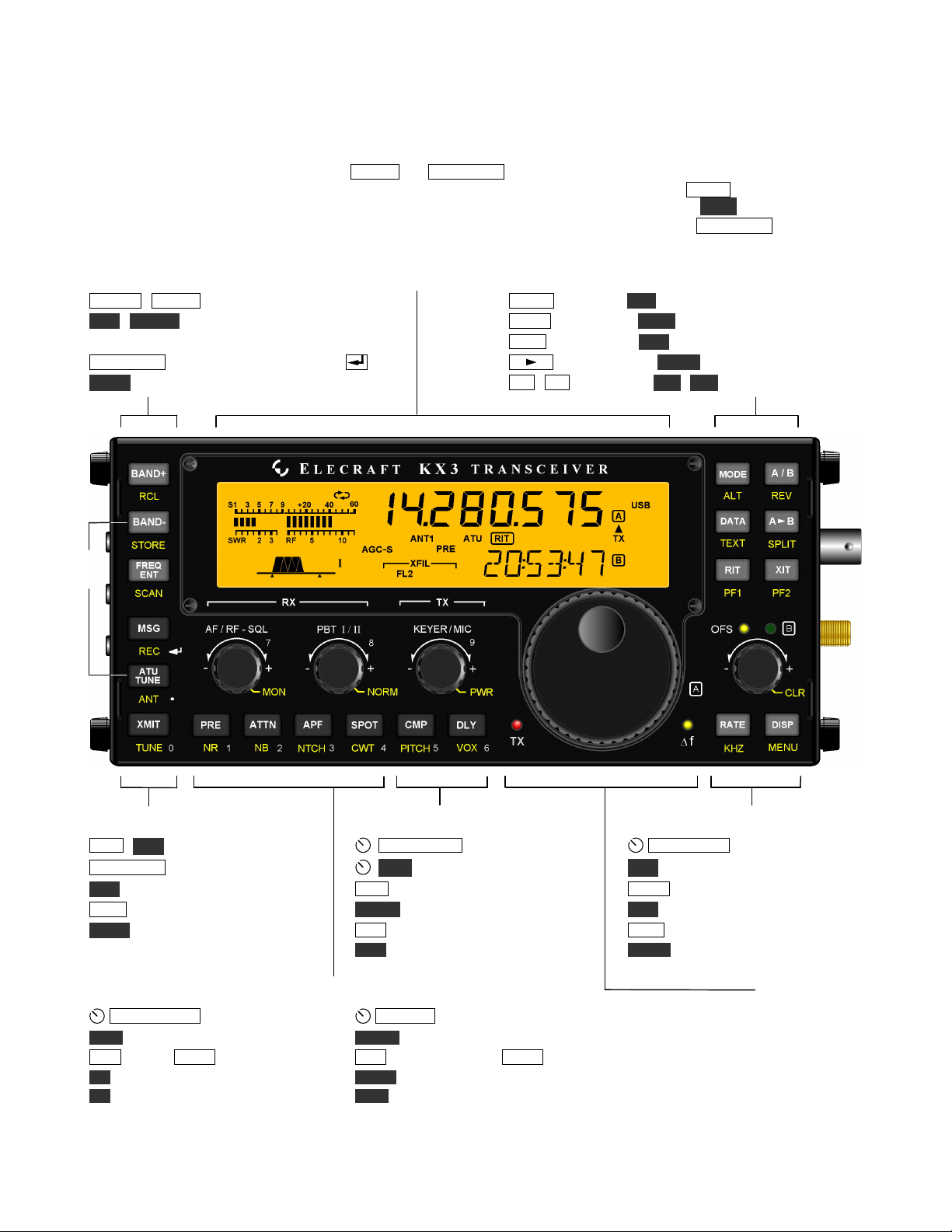
Control Panel Reference
All KX3 controls are described briefly here. For full details, refer to subsequent sections.
To Turn Power ON/OFF: Hold both the B A ND - and A TU TUN E switches for 2 seconds. (See ON/OFF label on left side.)
Tap Functions: Tap a switch or knob briefly to activate the function labeled on or above it, e.g. BAND+ .
Hold Functions: Hold the control for about 1/2 second to activate the function labeled below, e.g. MENU .
Numeric Keypad: Switches and knobs at lower-left form a keypad (0-9/decimal/enter). Used with F R EQ E N T , etc.
Band Selection Display Operating Mode and VFO Setup
B AN D+ / B A ND - Band up/down MOD E Basic mode; AL T Alternate mode (e.g. LSB/USB)
R CL / ST O R E Frequency memories; D AT A Data submode; TE XT Text decode setup
per-band: tap 1-4; general purpose (00-99): use VFO A A / B VFO A/B swap; R EV VFO or repeater reverse
FRE Q EN T Direct freq. entry (use # keys, then ) A B Copy VFO A to B; SP L IT Split RX/TX
S CA N Scan from VFO A to VFO B R IT / X IT RX/TX offset; PF 1 / PF2 Prog. function
Transmit / ATU Control Transmit Settings Offset / VFO B and Misc.
MS G / RE C Message play/record
K E Y ER /M I C WPM; mic gain
O F S /V F O B RIT/XIT or VFO B
A T U T U N E Start auto. antenna tune P W R Set power level C L R Clear RIT/XIT offset
A N T Select ANT. 1/2 (KXAT100 opt.) C M P Speech compression * R A T E Select 1 / 10 Hz VFO A/B steps
X M I T Enter transmit mode (PTT) P I T CH CW sidetone; FM tone * K H Z Select coarse VFO A/B steps
TU N E Transmit CW carrier at PWR level DL Y CW QSK delay; VOX delay * D I S P Show voltage etc. on VFO B *
(or MENU:TUN PWR level, if lower) VO X VOX/PTT (CW/voice separate) ME N U Use VFO B to select, A to edit
Receive Settings VFO A
A F / R F - SQ L Receiver gain control
P B T I /I I Passband tuning (I=WIDTH/LO, II=SHIFT/HI) Transmit LED
MO N Monitor level (CW/voice separate) * N O R M Filter passband normalization (per-mode) Delta-F LED
P R E Preamp; A T TN Attenuator A P F Audio peaking filter; S P OT CW spot tone
N R Noise reduction * N T C H Autonotch (SSB) or manual notch (CW) *
N B Noise blanking * C W T CW/DATA tuning aid (uses upper portion of S-meter)
* To adjust the parameter for this function, use the knob immediately above the switch.
ON /
OFF
Page 2
8
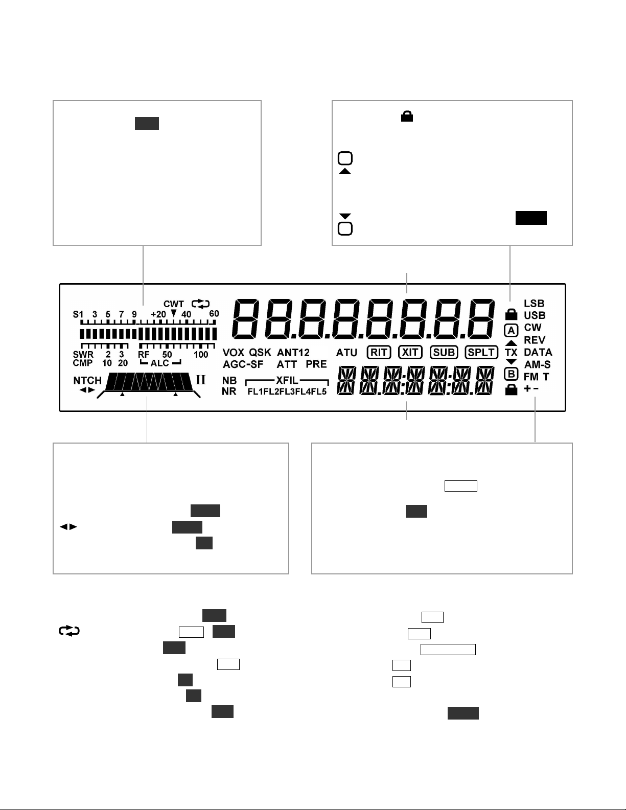
Display (LCD)
Bar graph, receive mode: Normally acts
as an S-meter. If C W T is turned on, the
right half of the S-meter becomes a tuning
aid.
Bar graph, transmit mode: Normally
shows SW R and R F output. In voice and
data modes, the bar graph shows CM P
(compression) and AL C whenever mic
gain or compression are adjusted.
VFO Icons: Shows that a VFO is locked.
The TX icon points to the transmit VFO:
TX
A
VFO A is the transmit VFO
TX
B
VFO B is the transmit VFO; see
VFO A
VFO B
Filter Passband Graphic: Shows
location of receive passband
Filter Icons:
NT C H Notch filtering on (N T C H)
Manual notch (NT C H)
I / II PBT filter function (I/ I I)
XFI L Extended filtering (FL1 -F L 5 )
Mode Icons
Basic modes (LSB or U S B, C W , D AT A , A M , or
FM ) are selected by tapping M O D E . Alternate modes
(CW R EV, D A T A R E V, A M- S, F M +/- ) are
selected by holding AL T . LS B and U SB are alternates
of each other. In SSB mode the + icon indicates
ESSB. T indicates FM/tone, CW/DATA text decode,
or AM-Sync auto-tracking.
Other Icons:
CW T CW/data tuning aid on (CW T )
Message play/rec (M S G / RE C )
VO X VOX enabled (V O X )
QS K Full break-in CW enabled (D L Y )
NB Noise blanker on (NB )
NR Noise reduction on (NR )
AN T Antenna 1 /2 , KXAT100 (AN T )
AT T Attenuator on (AT T )
PR E Preamp on (PR E )
AT U ATU enabled (AT U T U NE )
RI T RIT on (R IT )
XIT XIT on (X I T )
SU B Dual-watch enabled
SPL T Split mode in effect (SP L I T )
SPLIT
 Loading...