


ELECRAFT→ K3S
HIGH-PERFORMANCE
160 – 6 METER TRANSCEIVER
OWNER’S MANUAL
Revision A1, May 26, 2015
Copyright © 2015, Elecraft, Inc.
All Rights Reserved
Contents
A Note to K3S Owners .................................... |
3 |
Key to Symbols and Text Styles...................... |
3 |
Quick-Start Guide ............................................ |
4 |
Introduction...................................................... |
7 |
K3S Features........................................................ |
7 |
Specifications ...................................................... |
8 |
Customer Service and Support .......................... |
10 |
Front Panel..................................................... |
11 |
Control Groups .................................................. |
11 |
Display (LCD) ................................................... |
12 |
LEDs.................................................................. |
13 |
Front Panel Connectors ..................................... |
13 |
Primary Controls ............................................... |
13 |
Multi-Function Controls .................................... |
14 |
VFO Tuning Controls........................................ |
14 |
Keypad............................................................... |
15 |
Memory Controls............................................... |
16 |
Message Record/Play Controls.......................... |
16 |
RIT and XIT Controls ....................................... |
16 |
Rear Panel ...................................................... |
17 |
Connector Groups.............................................. |
17 |
Control and Audio Connections ........................ |
18 |
Basic Operation ............................................. |
23 |
Receiver Setup................................................... |
25 |
Reducing Interference and Noise ...................... |
27 |
Transmitter Setup .............................................. |
28 |
Voice Modes (SSB, AM, FM)........................... |
30 |
CW Mode .......................................................... |
32 |
Data Modes........................................................ |
33 |
Advanced Operating Features........................ |
35 |
Text Decode And Display ................................. |
35 |
CW-to-DATA.................................................... |
36 |
Tuning Aids: CWT and SPOT .......................... |
36 |
Audio Effects (AFX) ......................................... |
37 |
APF and Dual-Passband CW Filtering.............. |
37 |
Receive Audio Equalization (EQ) ..................... |
37 |
Transmit Audio Equalization (EQ) ................... |
37 |
SPLIT and Cross-Mode Operation .................... |
38 |
Extended Single Sideband (ESSB).................... |
38 |
General-Coverage Receive ................................ |
38 |
VFO B Alternate Displays................................. |
38 |
Alarm and Auto Power-On................................ |
38 |
Using the Sub Receiver ..................................... |
39 |
Receive Antenna In/Out ................................... |
41 |
Buffered I.F. Output for Panadapters ............... |
41 |
Using the 100-550 kHz Range.......................... |
41 |
Using Transverters............................................ |
41 |
Scanning ........................................................... |
42 |
Main and Sub Receiver Antenna Routing ..... |
43 |
Preamp 2 Limitations........................................ |
45 |
Remote Control of the K3S............................ |
46 |
Options and Accessories ................................ |
47 |
Firmware Upgrades........................................ |
47 |
Configuration ................................................. |
48 |
Crystal Filter Setup ........................................... |
48 |
Module Enables ................................................ |
49 |
Miscellaneous Setup ......................................... |
50 |
VFO A Knob Friction Adjustment ................... |
50 |
VFO B Knob Friction Adjustment ................... |
51 |
Real Time Clock Battery Replacement ............ |
51 |
Calibration Procedures................................... |
52 |
Synthesizer........................................................ |
52 |
Wattmeter ......................................................... |
52 |
Transmitter Gain............................................... |
52 |
Reference Oscillator ......................................... |
53 |
Front Panel Temperature Sensor ...................... |
54 |
PA Temperature Sensor.................................... |
54 |
S-Meter and RF GAIN Control ........................ |
54 |
Menu Functions ............................................. |
55 |
MAIN Menu ..................................................... |
55 |
CONFIG Menu ................................................. |
57 |
Troubleshooting ............................................. |
69 |
Parameter Initialization..................................... |
72 |
Module Troubleshooting .................................. |
73 |
Theory Of Operation...................................... |
77 |
RF BOARD ...................................................... |
77 |
KAT3A (ATU) and KANT3 ............................ |
79 |
KIO3B (Audio/Digital I/O) .............................. |
79 |
Front Panel and DSP......................................... |
79 |
KREF3 (Ref./2nd LO)........................................ |
81 |
KSYN3A (Synthesizer) .................................... |
81 |
Firmware........................................................... |
81 |
K3S Block Diagram .......................................... |
83 |
Appendix A: Crystal Filter Installation.......... |
84 |
Index .............................................................. |
88 |
2

A Note to K3S Owners
On behalf of our entire design team, we’d like to thank you for choosing the Elecraft K3S transceiver.
The K3S is the same size and weight (~9 lbs.) as its predecessor, the K3. Yet nearly all internal modules have been redesigned, providing enhanced performance and many new features. These include:
•Ultra low-noise synthesizer for exceptional receiver dynamic range and transmit signal purity
•USB port for convenient, single-cable computer control and digital audio interface (an RS232 port is provided, as well, for station compatibility and P3 interfacing); pg. 18
•Built-in second preamp for weak-signal work on 12, 10, and 6 meters; pg. 25
•Three attenuator settings (5/10/15 dB) to optimize performance in strong-signal conditions; pg. 25
•Improved audio circuitry for clean, low-distortion stereo speaker output; pg. 80
•Low-loss ATU option with a true bypass relay, maximizing efficiency with every antenna
•Accurate high-speed CW transmit timing, even when using SPLIT, RIT, and XIT
•100-550 kHz coverage, including low-level 630-meter (472 kHz) transmit; pg. 41
Exterior changes include all-stainless-steel hardware, new display bezel, and a soft-touch VFO tuning knob.
With its unique combination of compact size and world-class performance, your new K3S can handle the most demanding operating situations, whether you’re at home or halfway around the world.
73,
Wayne, N6KR
Eric, WA6HHQ
Key to Symbols and Text Styles
LSB
 .
.  .
.
 X M IT
T U N E
 SQL
SQL

 P W R
P W R
 M O N
M O N
MAIN:VOX GN
CONFIG:KAT3
Important – read carefully
Operating tip
LCD icon or characters
LED
Enter keypad function
Tap switch function (labeled on a switch)
Hold switch function (labeled below a switch; hold for 1/2 sec. to activate)
Rotary control without integral switch
Tap switch function of rotary control (labeled above a knob)
Hold switch function of rotary control (labeled below a knob; hold for 1/2 sec.)
Typical MAIN menu entry
Typical CONFIG menu entry
3

Quick-Start Guide
To get started using your K3S right away, please read this page and the two that follow, trying each of the controls. The text uses braces to refer to numbered elements in the frontand rear-panel illustrations below. For example, {1} in the text refers to 1 . Later sections provide greater detail on all aspects of K3S operation.


 The first thing you need to know about the K3S is that most switches have two functions. Tap (press briefly) to activate the function labeled on a switch. Hold for½toabout1 second t o activate the function labeled below the switch. In the text, tap functions are shown like this example:
  M E N U
 . An example of a hold function is C O N F I G . Additional typographical conventions are shown on the previous page.
Try tapping  M E N U
 {8}. This brings up the M A IN menu. Rotating VFO B {19} selects menu entries, while rotating VFO A {22} changes their parameters. Tap
  M E N U
 again to exit the menu.
4

Connections
The Basics
Filter Controls
Voice Modes
{1}
CW Mode
{37}
Data Modes
{33}
• Connect a power supply to the DC input jack {26} (see Specifications, pg. 8).
• On the K3S /100, a circuit breaker is provided on the fan panel for the 100-W stage {39}.
• You can power an accessory device from the switched DC output jack {40} (1.0 A max).
• Connect antenna to ANT1 {29} and ground {38}. With an ATU (pg. 24), you can also use ANT2 {28}. AUX RF {27} is for the sub RX; see pg. 17. ANT3 {30} is used with the internal 2-m module (K144XV). Connect an RX-only antenna to RX ANT IN {35}.
• Press  P O W E R
 {5} to turn on the K3S. If there are any error indications, refer to pg. 74.
• T A P
T A P and H O L D Functions: Tapping briefly activates the function labeled on a switch.
Holding for about 1/2 second activates the function labeled below a switch.
• Tap either end of  B A N D
 {7} to select a band, and
  M O D E
 {6} for the mode. Set AF gain using
  AF {2}. Set
  RF to max. Plug phones in at {3}. For SUB controls, see pg. 39.
•The large knob {22} controls VFO A (upper display, {10}). The medium knob {19} controls VFO B (lower display, {11}). VFO A is main RX/TX except in SPLIT (pg. 38).
• CMP / PWR is one of four multifunction controls {24}. Each has two primary functions, indicated by green LEDs. The knob has a built-in switch; tap it to select either CMP (compression level) or PWR (power output). Hold the knob in to access its secondary function, MON itor level. Tap again to restore the primary function.
• |
Rotate the |
SHIFT / LO CUT and |
HI CUT / WIDTH controls {23} to adjust the filter |
|
|
passband. Crystal filters FL1 -FL5 are automatically selected as you change the band- |
|||
|
width. Tap either knob to select shift/width or hi cut/lo cut. (See filter info, pg. 85.) |
|||
• |
Hold |
SHIFT / LO CUT to NORM alize the bandwidth (e.g., 400 Hz CW, 2.8 kHz SSB). |
||
• |
Hold |
HI CUT / WIDTH to alternate between two filter setups, I and II (per-mode). |
||
• |
Tap X F I L {13} to select crystal filters manually; this also removes any passband shift. |
|||
• |
Hold |
M E T E R {8} to see CMP / ALC levels. While talking, set MIC {25} for 4-7 bars |
||
|
of ALC, and |
CMP for the desired compression. Then return to SWR / PWR (pg. 30). |
||
• |
Optional: Hold T E S T {6} for TX TEST mode; allows off-air TX adjustments (pg. 13). |
|||
•Hold  CMP / PWR {24} to set speech MON itor level; tap to return to CMP / PWR .
•Hold V O X {7} to select PTT or VOX . Hold  SPEED / MIC to set VOX DELAY .
•Details: VOX, pg. 31; TX EQ, pg. 37; MIC SEL, pg. 55; SSB/AM/FM, pg. 30.
• SPEED {25} sets the CW keyer speed. Hold this knob to set semi-break-in DELAY .
Hold Q S K {7} to select full QSK (pg. 32.). Hold VOX {7} to select hit-the-key CW.
• Hold P I T C H {18} to set sidetone pitch. Hold  CMP / PWR to set sidetone MON level.
•Tap  C W T
C W T {18} for tuning aid {9} (pg. 36). With CWT on,
  S P O T
 auto-spots (pg. 32).
•To select CW text decode/display mode, hold T E X T D E C {18}; rotate VFO B (pg. 32).
• |
CW keying is converted to DATA in FSK D and PSK D modes (below and pg. 36). |
• |
Hold A P F {13} to turn on audio peaking (APF) or dual-passband filtering (pg. 32). |
• Tap M O D E {6} until you see the DATA icon turn on (see Data Modes, pg. 33). |
|
• |
Hold D A T A M D {18}. Use VFO B to select from: DATA A (PSK31, JT65, and other |
|
soundcard-based modes), AFSK A (soundcard-based RTTY), FSK D (RTTY via data |
|
input or keyer), or PSK D (PSK via data input or keyer). VFO A selects data baud rate |
|
for internal encoder/decoder, if applicable. A P F turns on an RTTY filter (DTF, pg. 34). |
•Hold P IT C H {18} to select mark tone and shift (for encoder/decoder and RTTY filter).
•Hold T E X T D E C {18} to set up text decode.  C W T
C W T shows tuning aid (pg. 36).
5

VFOs
and RIT/XIT
Transmit,
ATU, and
Antenna
Controls
Preamp and
Attenuator
NB, NR,
and Notch
SPLIT,
BSET, and SUB
Memories,
Messages, and
DVR
Menus and
Switch Macros
Other
Features
• R A T E
 {21} selects 10 or 50 Hz VFO/RIT tuning. See VFO menu entries, pg. 57.
• F I N E
 {21} selects 1-Hz steps. C O A R S E selects large steps (MAIN menu, VFO CRS).
• Tap  F R E Q E N T
 {21} to enter frequency in MHz using numeric keypad & decimal point.
Tap return ( |
|
|
) to complete the entry, or tap F R E Q E N T again to cancel (pg. 15). |
|
|||
|
|
•Hold S C A N to start/stop scanning. S C A N must be preceded by a memory recall (pg. 42).
•The  R IT
R IT and
and  X IT
X IT offset knob {17} has LEDs that show -/0/+ offset (pg.16). Tap
  C L R
C L R {16} to zero the offset. Hold
  C L R
C L R for > 2 sec. to add the offset to VFO A, then zero it.
•The T X LED {4} indicates that the K3S is in transmit mode. The ∆ f LED turns on if the RX and TX frequencies are unequal, e.g. S P L IT ,  R IT
R IT /
/ X IT
X IT , cross-mode (pg. 13).
• X M IT
 {8} is equivalent to PTT {36}. T U N E puts out full CW power in any mode.
•  A T U T U N E
 {8} initiates antenna matching (pg. 24). A T U enables or bypasses the ATU.
• A N T
A N T selects A N T 1 or A N T 2 .
  R X A N T
 selects main or R X antenna (KXV3B module).
• |
Tap P R E {13} to turn on the preamp (pg. 25). On 12-6 m, preamp 2 can be used. |
• |
Hold A T T {13} to turn on the attenuator (pg. 25). Hold A T T for 2 seconds to go into the |
|
MAIN:ATTEN menu entry; per-band attenuation level can be set to 5/10/15 dB. |
• |
Tap N B {12} to enable DSP and I.F. noise blanking. Hold L E V E L to set DSP NB level |
|
(VFO A) and I.F. NB level (VFO B). Fully CCW is OFF in both cases. (Pg. 27.) |
• |
Tap N R {12} to turn on noise reduction (saved per-mode). Hold A D J to tailor noise |
|
reduction for the present band conditions (pg. 27). |
• |
N T C H {12} turns on auto-notch in SSB mode, manual notch in others. M A N turns on |
|
manual notch in any mode, and is also used to adjust manual notch frequency (pg. 27). |
• |
Hold S P L IT {13} to enter split mode (RX on VFO A, TX on VFO B). If VFOs A and B |
|
are on different frequencies in SPLIT mode, the Delta-F LED (∆ f ) will turn on (pg. 13). |
• |
Hold B S E T {13} to adjust VFO B / sub RX settings independently of VFO A (pg. 39). |
•Tap  S U B
S U B {20} to turn on the sub receiver (pg. 39). VFO B controls its frequency.
• Hold D IV {20} to engage diversity mode (pg. 40), which can reduce signal fading.
•VFO B can be linked (slaved) to VFO A using CONFIG:VFO LNK menu entry.
•To store a frequency memory, tap  V
V  M
M {14}, then: tap
  M 1
M 1 -
- M 4
M 4 {15} to save a per-band quick memory; or tap
  0
0 -
- 9
9 to save a general-purpose quick memory; or rotate VFO A to
select from memories 0-99, then tap  V
V  M
M again to save. Tap
  M
M  V
V to recall. (Pg. 16.)
• R E C
R E C and
and  M 1
M 1 -
- M 4
M 4 {15} are also used to record & play voice/CW/DATA messages. The KDVR3 option is required for voice messages and A F R E C / A F P L A Y (pg. 31).
•  M E N U
 & C O N F IG {8} access the MAIN and CONFIG menus. VFO B selects entries; VFO A changes parameters. In general, CONFIG menu entries are used less often.
•Tapping  D IS P
 {8} within menus shows information about each entry on VFO B (pg. 55).
•Menu entries can be assigned to programmable switches P F 1 , P F 2 {16} and  M 1
M 1 -
- M 4
M 4 {15} (pg. 55). These switches can also be used to create custom SPLITs, etc. (macros, pg. 23).
• RX and TX EQ (MAIN menu) provide 8 bands of receive/transmit equalization (pg. 37).
• Tap  A F X
A F X {18} to enable the selected audio effect (see CONFIG:AFX MD, pg. 55).
•Tap  D IS P
 {8} and use VFO B to show time, supply voltage, etc. on VFO B (pg. 38).
•The ALARM function (MAIN:ALARM menu entry) can be used to remind you about a contest, net, or QSO schedule, and can even turn the K3S on at alarm time (pg. 38).
•The KIO3B module provides a rich set of AF {34} and digital {31-33} I/O (pg. 17).
6

Introduction
This comprehensive manual covers all the features and capabilities of the Elecraft K3S transceiver. We recommend that you begin with the Quick-Start Guide (pg. 4). The Front Panel section (pg. 11) and Rear Panel section (pg. 17) are for general reference. Basic Operation (pg. 23) and Advanced Operation (pg. 35) fill in the details.
 Anytime you add new filters or options, refer to Configuration (pg. 48) for setup instructions.
K3S Features
The K3S offers a number of advanced features to enhance performance and versatility:
Receiver
•Up to five crystal roofing filters with bandwidths as narrow as 200 Hz (pg. 25)
•Optional high-performance sub receiver, also with up to five crystal filters, allows true diversity receive (pg. 39)
•Second preamp for weak-signal work on 12-6 meters (pg. 25)
•Three attenuation settings (pg. 25)
•Narrow ham-band front-end filters, plus wider band-pass filters for general-coverage receive with KBPF3A option (pg. 47); KPF3A also provides good sensitivity down to 100 kHz, including 2200-m and 630-m bands (pg. 41)
DSP
•32-bit I.F. DSP for advanced signal processing, including full stereo and other binaural effects (pg. 37)
•Passband tuning and programmable DSP/crystal filter presets (pg. 14)
•8-band transmit and receive EQ (graphic equalization) (pg. 37)
•Versatile digital voice recorder (DVR) option (pg. 31)
CW and Digital Modes
•Built-in digital-mode demodulation with text displayed on the LCD (CW, RTTY, PSK31/PSK63) (pg. 35)
•APF (audio peaking filter) for digging out weak signals in CW mode (pg. 32)
•Internal CW-to-RTTY or CW-to- PSK31/PSK63 encoding for casual digitalmode QSOs without a computer (pg. 36)
•CW decoded and displayed as you send – great for improving CW skills (pg. 35)
•Automatic CW/data signal spotting and manual fine-tuning display (pg. 32)
User Interface
•Dual VFOs with independent modes, bands, and filter settings (pg. 14)
•100 memories with alphanumeric labels, plus 4 quick-memories per band (pg. 16)
•Dedicated message play controls for use in CW, data, and voice modes (pg. 32)
•Real-time clock/calendar with alarm and automatic power-on (pg. 38)
•Utility displays show voltage, current drain, RIT/XIT offset, front panel temperature, PA heat sink temperature, etc. (pg. 38)
•Built-in menu help text (pg. 23)
•Programmable switch “macros” to automate often-used operations (pg. 46)
•Custom “power-on banner” can be displayed on power-up (set up using the K3 Utility program)
Connectivity
•Remote control via USB or RS232 (pg. 46)
•Line-level analog audio jacks, plus digital audio via the USB port (pg. 17)
•Firmware upgrades via the Internet (pg. 47)
•Front and rear mic and headphone jacks
•Full stereo audio with two speaker outputs
Options and Accessories (pg. 47)
•ATU, sub receiver, digital voice recorder, 100-W PA, 2-meter module, external reference lock, and other internal options
•Fully integrated P3 Panadapter, 500+ W KPA500 amplifier and KAT500 automatic antenna tuner, K3/0-Mini remote control panel, and other accessories
7

Specifications
Some specifications apply only if the corresponding option modules are installed (see Options, pg. 47).
GENERAL
Frequency Range |
Main and Sub Receivers: 100 kHz - 30 MHz and 44-54 MHz (see receiver Sensitivity |
|
spec). Transmitter: Amateur bands between 1.8 and 54 MHz (limits vary by country). |
|
144-148 MHz with K144XV option. 630 m (472 kHz) at ~0.5 mW) with KBPF3A. |
|
Expanded coverage of MARS allocations on request (U.S.). |
Tuning Step Sizes |
1, 10, 20, and 50 Hz fine steps; user-configurable coarse tuning steps (per-mode). |
|
Direct keypad frequency entry in either MHz or kHz. |
Frequency Memories |
100 general-purpose memories; 4 scratch-pad memories per band. |
Frequency Stability |
+/- 5 ppm (0-50 C) TCXO standard; +/- 1 ppm TCXO opt. (+/- 0.5 PPM typ., 0-50 C). |
|
K3EXREF option locks TCXO to an external 10-MHz reference (+/- 1 to 2 Hz typ.). |
Antenna Jacks |
50 ohms nominal. One SO-239 supplied (2nd ant. jack supplied with KAT3A ATU). |
|
BNC jacks for RX antenna in/out and transverter in/out (on supplied KXV3B module). |
Modes |
USB, LSB, AM, FM, CW, DATA (FSK D [direct], AFSK A [Audio], PSK D [Direct] |
|
and DATA A [Audio]). Built in PSK, RTTY, and CW text decode/display. |
VFOs |
Dual VFOs (A and B) with separate weighted tuning knobs |
Remote Control Port |
USB-B port and RS232 port (RJ45 jack plus supplied RJ45 to DE9 adapter). USB port |
|
can also provide line-level audio in/out on the same cable. |
Audio I/O |
Line-level isolated TX/RX audio interface (mono in, stereo out); front (1/4”) and rear |
|
(1/8”) stereo headphone jacks; stereo speaker jack. |
Transverter Interface |
Transmit, 0 dBm typ.; XVTR IN/OUT connectors (BNC) on supplied KXV3B |
|
module. KXV3B also includes connectors for K144XV internal 2-meter module. |
Buffered IF output |
BNC connector (KXV3B); see pg. 41 for interface recommendations. |
Other I/O |
Key/Keyer/Computer, Paddle, PTT In, and KEY Out. Band information output via |
|
binary interface and AUXBUS on ACC connector. |
Real-Time Clock/Calendar |
Accuracy: Approx. +/- 20 ppm (+/- 2 seconds/day). U.S. and E.U. date formats. |
|
Battery: 3 V coin cell (see pg. 51 for replacement instructions). |
Supply Voltage |
13.8 V nominal (11 V min, 15 V max). 17-22 A typical in TX for K3S/100, 3-4 A |
and Current |
typical in TX for K3S/10. 1.0 A typical RX (less sub receiver). When using reduced |
|
supply voltage (< 12 V), power output should be reduced (e.g. 70 W at 11 V). |
|
Recommended supply: 13.8VDC @ 25A, continuous duty for K3S/100; 13.8VDC @ |
|
6A for K3S/10. For best results, use the supplied 5 foot (1.53 m) power cable. When a |
|
battery is used, both sides of the battery cable should be protected by fast-blow fuses. |
Accessory DC output |
Switched, 1.0 A max; 13 V no-load, 12 V max load (@ Vsupply = 13.8 V) |
Weight (K3S/100) |
Approx. 8.5 lbs. (3.8 kg). With KRX3A sub receiver option, 9.5 lbs. (4.3 kg). |
Size |
Enclosure only, 4.0 x 10.7 x 10.0 in., HWD (10.2 x 27.2 x 25.4 cm). With projections, |
|
4.4 x 11.1 x 11.8 in. (11.2 x 28.2 x 30.0 cm). |
8
RECEIVER (Main and Sub)*
Sensitivity (MDS) |
HF, Preamp off: -133 dBm. Preamp 1: -138 dBm. Preamp 2 (12/10/6 m): -145 dBm. |
|
(Typical values, in |
Reduced sensitivity near 8.2 MHz (first I.F.) and from 44-49 MHz. Sensitivity |
|
500 Hz bandwidth) |
decreases gradually below 1.8 MHz due to intentional high-pass response at the T-R |
|
|
switch. (Use RX ANT input, XVTR IN, or sub receiver’s AUX input to avoid the |
|
|
high-pass filter loss.) Note: KBPF3A option required for full general coverage |
|
|
(including 100 to 1700 kHz). Sensitivity falls off below 200 kHz; MDS typically |
|
|
-115 dBm at 137 kHz (2200 m band) using RX ANT IN or XVTR IN. |
|
Dynamic Range |
IMD3 at 5 and 20 kHz spacing, 500 Hz BW: ~100 dB. Blocking: ~140 dB. |
|
Image and I.F. Rejection |
> 70 dB |
|
Audio Output |
2.5 W per channel into 4 ohms; typ. 10% THD @ 1 kHz, 2 W |
|
S-Meter |
NomµV,.S9 = 50 |
preamp 1 on; user-adjustable |
Preamp |
Preamp 1 (all bands): 10 dB; preamp 2 (12/10/6 meters): 20 dB |
|
Attenuator |
Main receiver: 5/10/15 dB levels, settable per-band. Sub receiver, 10 dB. |
|
Noise Blanker |
Adjustable, multi-threshold/multi-width hardware blanker plus DSP blanker |
|
Receive AF graphic EQ |
+/- 16 dB/octave, 8 bands |
|
Filter Controls |
IF Shift/Width & Lo/High Cut with automatic crystal filter selection |
|
* Receive specifications are guaranteed only within ham bands. Dynamic range measurements based on 400-Hz, 8-pole filter. See www.elecraft.com for full list of available crystal filters.
TRANSMITTER *
Output Power |
K3S/100: 0.1 W –100 W typ. Suggested max from 51-52 MHz, 85 W; 52-54, 70 W. |
|
K3S/10 (or K3S/100 with PA bypassed): 0.1 W –12 W, HF-10 m; 8 W max on 6 m. |
|
XVTR OUT: HF, -10 to +1.8 dBm; at 472 kHz (630 m), -3 dBm (see pg. 41). |
|
K144XV: ~10 W, 144-148 MHz. |
|
Note: K3S/100 output can be set up to 110 W. However, IMD and spurious products |
|
are specified at 100 W, the recommended maximum (lower on 6 m; see above). |
Duty Cycle |
CW and SSB modes, 100% 10-min. 100W key-down at 25 C ambient |
True RF Speech Processor |
Adjustable compression |
Transmit AF graphic EQ |
+/- 16 dB/octave, 8 bands |
SSB TX Bandwidth |
4 kHz max (> 2.8 kHz requires 6 kHz or 13 kHz crystal filter) |
VOX |
DSP-controlled, adjustable threshold, delay, and anti-VOX |
Full and Semi CW Break-In |
Adjustable delay; diode T/R Switching |
SSB Carrier Suppression |
> 50 dB |
Harmonic / Spurious Outputs |
> 50 dB below carrier @ 100W (> 60 dB on 6 meters) |
CW Offset/Sidetone |
300-800 Hz, adjustable (filter center frequency tracks sidetone pitch) |
Mic Connector |
Front panel, 8 pin; rear panel 3.5 mm; switchable DC bias |
* Transmit specifications are guaranteed only within ham bands.
9

Customer Service and Support
Technical Assistance
You can send e-mail to k3support@elecraft.com and we will respond quickly – typically the same day Monday through Friday. If you need replacement parts, send an e-mail to parts@elecraft.com. Telephone assistance is available from 9 A.M. to 5 P.M. Pacific time (weekdays only) at 831-763-4211. Please use e-mail rather than calling when possible since this gives us a written record of the details of your problem and allows us to handle a larger number of requests each day.
Repair / Alignment Service
If necessary, you may return your Elecraft product to us for repair or alignment. (Note: We offer unlimited email and phone support, so please try that route first as we can usually help you find the problem quickly.)
IMPORTANT: You must contact Elecraft before mailing your product to obtain authorization for the return, what address to ship it to and current information on repair fees and turn around times. (Frequently we can determine the cause of your problem and save you the trouble of shipping it back to us.) Our repair location is different from our factory location in Aptos. We will give you the address to ship your kit to at the time of repair authorization. Packages shipped to Aptos without authorization will incur an additional shipping charge for reshipment from Aptos to our repair depot.
Elecraft 1-Year Limited Warranty
This warranty is effective as of the date of first consumer purchase (or if shipped from the factory, the date the product is shipped to the customer). It covers both our kits and fully assembled products. For kits, before requesting warranty service, you should fully complete the assembly, carefully following all instructions in the manual.
Who is covered: This warranty covers the original owner of the Elecraft product as disclosed to Elecraft at the time of order. Elecraft products transferred by the purchaser to a third party, either by sale, gift, or other method, who is not disclosed to Elecraft at the time of original order, are not covered by this warranty. If the Elecraft product is being bought indirectly for a third party, the third party’s name and address must be provided at time of order to ensure warranty coverage.
What is covered: During the first year after date of purchase, Elecraft will replace defective or missing parts free of charge (post-paid). We will also correct any malfunction to kits or assembled units caused by defective parts and materials. Purchaser pays inbound shipping to us for warranty repair; we pay shipping to return the repaired equipment to you by UPS ground service or equivalent to the continental USA and Canada. For Alaska, Hawaii, and other destinations outside the U.S. and Canada, actual return shipping cost is paid by the owner.
What is not covered: This warranty does not cover correction of kit assembly errors. It also does not cover misalignment; repair of damage caused by misuse, negligence, or builder modifications; or any performance malfunctions involving non-Elecraft accessory equipment. The use of acid-core solder, water-soluble flux solder, or any corrosive or conductive flux or solvent will void this warranty in its entirety. Also not covered is reimbursement for loss of use, inconvenience, customer assembly or alignment time, or cost of unauthorized service.
Limitation of incidental or consequential damages: This warranty does not extend to non-Elecraft equipment or components used in conjunction with our products. Any such repair or replacement is the responsibility of the customer. Elecraft will not be liable for any special, indirect, incidental or consequential damages, including but not limited to any loss of business or profits.
10
Front Panel
This reference section describes all front panel controls, the liquid crystal display (LCD), LEDs, and connectors. Operating instructions are covered in later sections.
Control Groups
Primary Controls (pg. 13): These controls provide basic transceiver setup, including power on/off, band, operating mode, AF and RF gain and squelch, ATU and transmit controls, display modes, and menus.
Display (pg. 12): The LCD shows signal levels, VFO A and B frequencies, filter bandwidth, operating mode, and the status of many controls. The VFO B display is alphanumeric, so it can show decoded text from digital modes (CW, RTTY, PSK31/PSK63), as well as menus, time and date, help messages, etc.
Multi-Function Controls (pg. 14): The upper two knobs set up receiver DSP filtering. The lower two control transmit parameters, including keyer speed, mic gain, speech compression, and power output level. LEDs above each knob show which function is active; tapping the knob alternates between them. Pressing and holding these knobs (1/2 second or longer) provides access to secondary functions.
Keypad (pg. 15): This group of switches is numbered for use during memory store/recall and direct frequency entry, but each switch also has normal tap and hold functions. The upper row of switches are VFO controls. The remaining rows control receive-mode and miscellaneous functions, such as noise reduction and text decode/display.
Memories (pg. 16): These switches control frequency memory store/recall, message record/play, and audio record/playback (with the DVR).  M 1
M 1 -
- M 4
M 4 can also be used as up to eight tap/hold programmable function switches.
VFOs (pg. 14): The large knob controls VFO A; the smaller knob controls VFO B. The four switches between the VFO knobs select tuning rates and control related functions.
RIT/XIT (pg. 16): Three switches control RIT and XIT on/off and clear (offset zero). The OFS knob below the  R I T
R I T /
/ X I T
X I T switches selects the offset.
11

Display (LCD)
Multi-character displays: The 7-segment display (upper) shows the VFO A frequency. The 13segment display (lower) shows VFO B or text.
Bar graph, receive mode: The bar graph normally acts as an S-meter. If  C W T
C W T is turned on, the right half of the S-meter becomes a tuning aid (pg. 36).
Bar graph, transmit mode: The bar graph normally shows S W R and R F power output. The R F scale will be either 5 and 1 0 (low power) or 5 0
transmit scales can be changed to compression (C M P ) and A L C using M E T E R .
Filter Graphic: This shows the approx. bandwidth and position of the receiver’s I.F. passband. See
Filter Passband Controls, pg. 25.
Filter Icons:
N T C H Notch filtering on ( N T C H
 , pg. 27)
Manual notch (M A N , pg. 27)
I / II Shows selected preset (I / I I , pg. 14) XFIL Crystal filter selection (FL1 -FL5 )
Mode Icons:
Basic modes (LSB / USB , CW , DATA , AM , or FM ) are selected by tapping either end (Up/Down) of  M O D E
 . Alternate modes (CW REV , DATA REV , AM -S , FM +/-) are selected by holding
A L T . LSB and USB are alternates of each other. + icon on in SSB modes indicates ESSB (pg. 38).
T indicates FM/tone, CW/DATA text decode, or AM-Sync auto-tracking.
VFO Icons: The T X icon indicates |
is |
selected for transmit. In TX TEST mode, |
|
TX is inhibited externally, T X flashes |
). |
Shows that VFO A or B is locked |
). |
VFO A is the transmit VFO
TX
TX
SPLIT
Other Icons: |
|
CWT CW/data tuning aid on (C W T , pg |
|
DVR in use (A F R E C / A F P L A |
) |
VOX VOX enabled (V O X , pg. 13) QSK Full break-in CW enabled (Q S K , NB Noise blanker on ( N B
N B , pg. 15) NR Noise reduction on (
 N R
N R , pg. 15) ANT Antenna 1 or 2 (
 A N T
A N T , pg. 13) RX RX antenna in use (
 R X A N T
 , pg. ATT Attenuator on (A T T , pg. 15)
PRE Preamp on ( P R E
P R E , pg. 15); preamp2 is selected (pg. 25)
ATU ATU enabled (A T U , pg. 13) RIT RIT on ( R IT
R IT , pg. 16)
XIT XIT on ( X IT
X IT , pg. 16)
SUB Sub receiver on ( S U B
S U B , pg. 39) SPLT Split mode in effect (S P L IT , pg.
12
LEDs
TX [Red] Turns on in transmit mode.
 ∆ F [Yellow] The Delta-F LED turns on if transmit and receive frequencies or modes are different due to the use of SPLIT, RIT, or XIT.
 [Green] Eight LEDs show which functions are in effect for the Multifunction Controls (pg. 14).
( - ) 

 (+ ) RIT/XIT OFFSET If the
OFS control is centered, or you tap  C L R
C L R , the green LED turns on (offset = 0). Otherwise, the yellow
(-) or (+) LED will be on, indicating the direction of the offset. See  R I T
R I T ,
,  X I T
X I T , and
, and  C L R
C L R .
.
Front Panel Connectors
PHONES You can use either mono or stereo headphones at either the front- or rear-panel headphone jack. Also see  A F X
A F X (pg. 37).
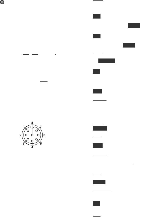
MIC An Elecraft MH2, MD2, Proset-K2, or other compatible mic can be used (see pinout below). To select the frontor rear-panel mic, and to turn bias on/off, use the MAIN:MIC SEL menu entry.
Bias must be turned on for electret mics (e.g. MH2, MD2, Proset). It must be off for dynamic mics (e.g. Heil mics using HC4 or HC5 elements).
Mic jack, viewed from front of K3
1Mic audio, low-Z (~600 ohms)
2PTT
3DOWN button *
4UP button *
5FUNCTION button *
68V (10 mA max)
7, 8 Ground
* See CONFIG:MIC BTN menu entry.
FP ACC This connector (RJ-45, 6 pins) is located on the bottom of the transceiver, near the VFO B knob. At present it is used only for factory test.
Primary Controls
 B A N D
 Tap left/right end to move among ham bands. CONFIG:BND MAP disables bands. For “quick” band switching, see CONFIG:MEM 0-9.
V O X Selects voice-operated or CW keyingoperated transmit (VOX icon on), or PTT (VOX icon off). Also see  D E L A Y (pg. 32) and CW VOX auto-off control (CONFIG:CW WGHT).
Q S K Selects either full break-in (QSK icon on) or semi break-in keying, if VOX is selected in CW mode. Also see  D E L A Y (pg.32).
 M O D E
 Tap the left or right end of this switch to select the operating mode. When DATA is selected, the D A T A M D switch is used to specify DATA-A, AFSK A, FSK D, or PSK D (pg. 33).
A L T In LSB mode, switches to USB (and viceversa). Also selects alternate modes, including:
CW REV , DATA REV , and AM - S (pg. 31). In
FM mode, selects + /- or simplex (pg. 31).
T E S T Selects TX TEST (TX LCD icon flashing); allows key/mic test without actually transmitting.
 P O W E R
 Turns the K3S on or off. Note: To ensure correct save of operating parameters, turn the K3S off before turning the power supply off.
 M E N U
 Displays MAIN menu (pg. 23).
C O N F IG Displays the CONFIG menu (pg. 23).
 X M IT
 Manually-operated transmit. Places the K3S into transmit mode (same as PTT, pg. 28).
T U N E Puts out a carrier at the present power level. Also TUNE Power Level (pg. 29).
 R X A N T
 Enables the receive antenna (pg. 24). If the sub RX is on, holding
  R X A N T
 alternates between the sub’s MAIN / AUX antennas (pg. 39).
 D IS P
 Shows an alternate display on VFO B, such as time, date, voltage, etc. (pg. 38).
M E T E R Selects voice transmit bar graph modes: SWR and RF , or CMP and ALC (pg. 30).
 A T U T U N E
 Matches the antenna (transmitting at up to 10 W) using the KAT3A ATU (pg. 24).
A T U Puts the ATU into normal mode (ATU icon on) or bypass mode (pg. 24).
 A N T
A N T Selects ANT 1 or 2 . In BSET mode with the sub receiver on, selects MAIN or AUX antenna for the sub receiver (pg. 39).
13
Dual-Concentric Potentiometers
 AF — SUB AF gain controls for main receiver (inner, or smaller knob) and sub receiver (outer ring, or larger knob).
 RF / S Q L — SUB RF gain (and/or squelch) controls for main and sub receiver.
Two menu entries are provided to control squelch directly: CONFIG:SQ MAIN, and SQ SUB. They can also be used to reconfigure the RF gain controls as squelch for either receiver, and to select FM-only or all-mode squelch. See Config Menu (pg. 57).
Multi-Function Controls
The upper two multi-function controls set up receiver filtering. The lower two controls adjust transmit settings. Each control has two primary functions (white labels) and a secondary function (yellow). Tap a control knob to alternate between its primary functions, indicated by two LEDs. Hold a knob (~1/2 second or longer) to select its secondary function.
Filter Controls
The primary functions of the filter controls are:
S H I F T |
Shift passband either direction |
L O C U T |
Adjust low-frequency response |
H I C U T |
Adjust high-frequency response |
W ID T H |
Adjust width of the passband |
As these settings change, so does the filter graphic. Crystal filters are selected automatically (or manually using  X F IL
 , pg. 15). Also see Filter Passband Controls (pg. 25).
The secondary functions of these controls are:
N O R M Normalize passband
Normalizing the passband sets the bandwidth to a fixed, per-mode value (e.g. 400 Hz in CW mode) and centers the passband. (Also see user-defined normal settings, NORM1 /2 , pg. 26.)
I / I I Select preset I or II (per mode)
Presets I and II each hold a continuously-updated DSP/crystal filter setup (pg. 26).
Transmit Controls
The primary functions of the transmit controls are:

 S P E E D
 Keyer speed in WPM, 8-50 (8-100
|
if CONFIG:CW QRQ is ON ) |
M IC |
Mic gain |
C M P |
Speech compression level |
P W R |
RF output power in watts (pg. 28) |
The present transmit mode determines which primary functions normally apply; for example, in CW mode, the 
 S P E E D
 /
/  M IC
M IC control defaults to
  S P E E D
 . You can always tap a knob to override the present selection.
The secondary functions of these controls are:
 D E L A Y VOX delay (voice/data) or CW semi- break-in delay, in seconds
 M O N Voice or data monitor level or CW sidetone and alert tone level
 You can optionally LOCK the MIC, CMP, and PWR control settings; see CONFIG:PWR SET.
VFO Tuning Controls
VFO A controls the upper frequency display. This is normally the RX and TX frequency. In SPLIT mode, VFO B controls the transmit frequency (pg. 38). VFO B also controls the sub receiver (pg. 39).
The controls to the right of VFO A include:
 F R E Q E N T
 Direct frequency entry (pg. 15)
S C A N |
Start or stop scanning (pg. 42) |
F IN E |
Select 1 Hz tuning for both VFOs |
|
and RIT/XIT offset |
C O A R S E Select coarse tuning rate (pg. 24) |
|
R A T E |
Select one of two normal tuning rates |
|
(10/50 or 10/20 Hz; pg. 24) |
L O C K |
Lock VFO A (use B S E T to lock B) |
S U B |
Turn sub receiver on/off (pg. 39) |
D IV |
Turn diversity mode on/off (pg. 40) |
 To link VFO B to VFO A, set CONFIG:VFO LNK to ON . This is not necessary in diversity mode, where VFO A always tunes both receivers.
 VFO A can optionally be coarse-tuned using the RIT/XIT offset control if both RIT and XIT are off . See CONFIG:VFO OFS.
14

Direct Frequency Entry
To jump to any frequency within the tuning range of the K3, tap  F R E Q E N T
 , then enter 1 to 3 MHz digits, a decimal point, and 0 to 3 kHz digits.
Follow this with Enter (  .
.  .
. ) to accept or
  F R E Q E N T
 to cancel. The decimal point is
optional if no kHz digits are entered, making it very easy to get to the low end of most ham bands.
Examples:
1.825 MHz: F R E Q E N T |
1 |
8 2 5 . |
|
|
. . |
|||
|
||||||||
|
|
|||||||
1.000 MHz: F R E Q E N T |
1 |
|
|
. |
|
|
|
|
|
|
|
|
|
|
|||
|
|
|
|
|
||||
50.100 MHz: F R E Q E N T |
|
5 0 . 1 |
|
|
. |
|||
|
|
|
|
|||||
|
|
|
||||||
 For frequencies under 1 MHz, start entry with a decimal point. If 4 or more digits are entered without a decimal point, a value in kHz is assumed.
Keypad
Keypad switches have the tap and hold functions listed below. They are also used for selecting quick memories 0-9, and for direct frequency entry.
VFO Controls (Upper row)
The upper row of numeric keypad switches is used to set up VFOs A and B. Their functions are:
A / B |
Exchange VFO A and B contents |
B S E T |
Set up VFO B and sub RX (see below) |
R E V |
Exchange VFO A and B temporarily |
|
(repeater RX/TX swap in FM-RPT) |
A B |
Copy VFO A frequency to VFO B; |
|
tapping twice copies all other settings |
|
(also see CONFIG:VFO B->A) |
S P L IT |
Enable SPLIT receive/transmit |
 If cross-mode operation is not allowed for the present VFO A and B modes, you’ll see SPL N/A if you try to enable SPLIT. If cross-mode operation is allowed, the mode icon for VFO B will flash as a warning. Tap any switch to cancel the flash.
Holding B S E T allows VFO B (and the sub receiver, if on) to be set up directly (pg. 39). As long as BSET is displayed, all VFO-related controls and display elements apply to VFO B. An alternative is to exchange VFOs with  A / B
A / B , set up VFO A, then exchange them again.
Receiver Control & Misc. (Lower Rows)
 Receiver control functions normally apply to VFO A/main receiver. If BSET is in effect, they apply to VFO B (and the sub receiver if turned on).
P R E |
Preamp on/off; also selects preamp 2 |
|
if enabled on 12/10/6 meters (pg. 25) |
A T T |
Attenuator on/off (5/10/15 dB, per- |
|
band; hold switch for 2 seconds to go |
|
directly to MAIN:ATTEN setting) |
A G C |
AGC slow/fast (also see CONFIG: |
|
AGC DCY, AGC HLD, and other |
|
AGC menu entries) |
O F F |
AGC off/on (when off, an AF limiter |
|
is available; see CONFIG:AF LIM) |
X F IL |
Select next available crystal filter |
|
(see CONFIG:FLx ON) |
A P F |
CW: APF or Dual-passband filtering |
|
(see CONFIG:DUAL PB); |
|
RTTY: dual-tone filtering (pg. 32) |
N B |
Noise blanker on/off (pg. 27) |
L E V E L |
Noise blanker levels (pg. 27); use |
|
VFO A knob to setup DSP blanker, |
|
and VFO B to setup I.F. blanker |
N R |
Noise reduction on/off (pg. 27) |
A D J |
Noise reduction parameter adjust; use |
|
VFO B knob (pg. 27) |
N T C H |
Notch filter auto/manual/off (pg. 27) |
M A N |
Manual notch frequency (pg. 27); use |
|
VFO B knob |
S P O T |
Spot tone on/off (manual), or auto- |
|
spot (if CWT is on; pg. 36) |
P IT C H |
CW sidetone PITCH , PSK pitch, |
|
FSK / AFSK MARK tone and shift |
|
(pg. 33), or FM tone setup (pg. 31) |
C W T |
CW/data tuning aid on/off (pg. 36); |
|
turn on to use auto-spot |
T E X T D E C |
Text decode, CW or DATA (pg. 35); |
|
use VFO B knob to select mode |
A F X |
Audio effects on/off (pg. 37); use |
|
CONFIG:AFX MD to set mode |
D A T A M D |
DATA mode selection (pg. 33); use |
|
VFO B knob |
15

Memory Controls
Frequency Memories
The K3S has 100 general-purpose memories (0099), plus per-band memories (M1-M4 on each band). Each memory holds VFO A and B frequencies, modes, filter presets, antenna selection, and other settings. Each can have a text label of up to 5 characters (A-Z, 0-9, and various symbols).
 The Elecraft Frequency Memory Editor software application can be used to simplify setup and use of memories. Refer to our K3/K3S software web page for details.
To store a general-purpose memory (0 0 -9 9 ): First tap  V
V  M
M (VFO to Memory), then locate the desired memory using the VFO A knob. The VFO A frequencies stored in each memory will be shown as you scroll through them. When you reach the desired memory number, tap
  V
V  M
M again to store, or tap
  M
M  V
V to cancel the operation.
To recall a general-purpose memory: Tap
 M
M  V
V , then select memory 0 0 -9 9 using VFO A. Tap
  M
M  V
V  again to exit.
Memories 00-09 are quick memories, accessible with just two switch taps. These could be used to get to a starting point in each of 10 ham bands.
Memories  M 1
M 1 –
–  M 4
M 4 are per-band quick memories. For example, you might set up
  M 1
M 1 for each band’s CW segment,
  M 2
M 2 for the SSB segment, etc.
 Memories 00-09 can act as if they were band switches; see CONFIG:MEM 0-9.
To store or recall quick memories: Tap  V
V  M
M or
or  M
M  V
V as before, but instead of rotating VFO A, tap
  0
0 -
-  9
9 or
or  M 1
M 1 -
-  M 4
M 4 .
.
To erase one or more memories: While scrolling through memories to save or recall, tap  C L R
C L R . Not applicable to per-band quick memories (
 M 1
M 1 -
- M 4
M 4 ).
).
To add or change a memory’s text label: First tap
 M
M  V
V , then select a memory (0 0 -9 9 ) using VFO A. Next, rotate VFO B to select each label position in turn as indicated by the flashing cursor. Use VFO A to change characters. After editing, tap
  M
M  V
V again. (Labels can be edited at any time, including when you initially store a memory using
  V
V  M
M .)
.)
 Adding an asterisk (*) at the start of a label designates a channel-hopping memory (pg. 42).
16
Digital Voice/Audio Recorder (KDVR3)
The DVR can continuously record receive audio (up to 90 seconds). To start/stop audio record, hold A F R E C . To start/stop playback, hold A F P L A Y . The  icon flashes during DVR use.
Playback position (0-90 sec.) is shown on the VFO B display; “*” appears if you’re within the most recent segment. Use VFO B to change the position.
For DVR voice message record/play, see pg. 31.
Message Record/Play Controls
Five switches provide record and playback of outgoing messages:  M 1
M 1 ,
,  M 2
M 2 ,
,  M 3
M 3 ,
,  M 4
M 4 and
and  R E C
R E C . These switches provide single-tap play, hold-to- repeat, and other functions that are convenient for contests and for sending often-repeated text or voice messages during QSOs. CW messages can be viewed and edited using K3 Utility, if desired.
For details on CW message record/play, see pg. 32. The same messages can be used with CW-to-DATA (pg. 36). For voice message record/play, see Digital Voice Recorder (pg. 31).

 M 1
M 1 through
  M 4
M 4 can alternatively be used as tap or hold programmable function switches (pg. 23).
RIT and XIT Controls
 R IT
R IT RIT (receive incremental tuning) on/off.
P F 1 Programmable function switch (pg. 23)
 X IT
X IT XIT (transmit incremental tuning) on/off.
P F 2 Programmable function switch (pg. 23)
 C L R
C L R Sets RIT/XIT offset to 0. Hold for 2 seconds to copy present RIT offset to VFO A before clearing.
The RIT/XIT offset control sets the offset for  R IT
R IT and
and  X IT
X IT . Three LEDs above the control show at a glance whether an offset is in effect (pg. 11).
 If CONFIG:RIT CLR is set to UNDO ON , tapping
  C L R
C L R will alternate between 0 .00 and the last non-zero offset selected, if any.
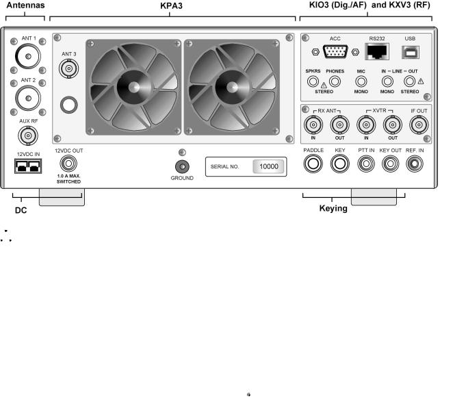
Rear Panel
Connector Groups
 The appearance of your rear panel may vary depending upon the options installed.
Antennas: ANT1 (SO-239) is standard. ANT2 (SO-239) is supplied with the KAT3A ATU option, which includes an antenna switch controlled from the front panel. Both jacks are nominally 50 ohms when the ATU is bypassed. AUX RF (BNC) is for use with the KRX3A option; see pg. 39 and pg. 43. ANT3 (BNC, on the KPA3A option panel) is the antenna jack for the optional K144XV 2-m module.
DC: 12 VDC IN jack is an Anderson PowerPole connector rated at 30 amps. (See Specifications, pg. 8, for detailed power requirements.)
12 VDC OUT (RCA/Phono) provides up to 1.0 A (switched) for use with accessory devices.
Ground Terminal: A good station ground is important for safety and to minimize local RFI.
KPA3A: This option panel is blank in the K3S/10 except for ANT3 (see above). In the K3S/100, the blank panel is replaced with the fan panel shown, which includes a circuit breaker.
KIO3B (pg. 19): Provides computer, auxiliary control, and audio connections. The USB connector handles both digitized line-level audio and data (pg. 18). The RS232/P3 jack (RJ45) is used with the P3 and/or for RS232 station control; an RJ45-DE9 adapter is included (pg. 19).
KXV3B: Provides a variety of RF I/O signals, including receive antenna in/out (pg. 41), transverter in/out (pg. 41), a buffered I.F. output for use with the Elecraft P3 (pg. 47), and internal I.F. connections for the K144XV 2-m module. Preamp 2, for weak-signal work on 12/10/6 m, is also included on this module (see pgs. 25 and 45).


 External preamps such as the PR6-10 are not needed with the K3S. See Preamp 2 (pg. 25).
Keying: PADDLE (1/4” jack) is the keyer paddle input (see CONFIG:CW PDL). KEY (1/4” jack) can be used with a hand key, external keyer, computer, or other device. PTT IN (RCA/Phono) is for use with a footswitch, etc. KEY OUT (RCA/ Phono) is the amplifier T-R relay keying output, capable of keying up to +200VDC @ 5A.
REF IN (SMA): External 10-MHz reference input for use with the K3EXREF option module (see
CONFIG:REF CAL and CONFIG:XVn OFS).
17

Control and Audio Connections
The K3S provides a full complement of station control and audio interfaces on the KIO3B panel. These interfaces are described in this section.
USB Port (Control and Audio)
The USB port can be used for computer-based remote control. It also acts as the equivalent of a built-in USB sound card, eliminating the need for external converters and additional cables.
A single USB cable can handle all of these interface requirements:
•commands from logging/contesting software
•line-level audio input/output (audio is digitized by the KIO3B’s USB interface)
•PTT and CW keying (via “DTR” and “RTS”)
Most software applications will work with USB instead of RS232. They will recognize the transceiver’s USB port as a “COM” port, and/or as a sound device, selectable from within the application.
An Elecraft P3 Panadapter can be connected directly to the K3S even when the USB port is used with your computer. See details at right.
To connect a computer to the K3S via USB:
•Connect the supplied USB cable from the K3S to any available USB port on your computer.
(See illustration below.)
•If you also have a P3, connect it to the RS232/P3 port as shown, using an Elecraft model CBLP3Y cable.
•Set the CONFIG:RS232 menu parameter to U S B . Exit the menu.
•With the USB cable plugged in and the K3S turned on, determine which COM or sound device ports have been assigned to the K3S. This can be done from within applications. On Windows PCs, an alternative is to locate the Device Manager (Start > Control Panel > System > Hardware), and view its list of Ports. When you plug in the USB cable from the K3S, a new COM port will appear in the list.
•If you plan to do PTT or CW keying from the computer, see PTT and Keying (next page).
Optional: Using LINE IN/OUT jacks with USB
We recommend using the digital audio line-in/out capability provided by the USB cable. The analog LINE IN/OUT jacks can then remain unconnected. See pg. 22 for further details on LINE IN/OUT.
18

RS232 / P3 Panadapter Port (RJ45)
The RS232/P3 port can be used with an Elecraft P3 Panadapter, or with a computer’s RS232 interface.
 In most cases it is preferable to connect the computer to the transceiver’s USB port as described on pg. 18. However, RS232-only installations can also be used, as discussed on this page.
An adapter cable to convert RJ45 to DE9 (RS232 standard, female) is supplied with the K3S (Elecraft #E980297). This adapter allows you to connect the K3S to a P3, or to a computer via a user-supplied RS232 cable, as shown below. The adapter cable’s DE9 connections are shown on the next page. RJ45 jack connections are shown below.
If you plan to use the RJ45 jack for PTT or keying from the computer, see PTT and Keying (pg. 20). Typically such connections would be made at the DE9 end of the supplied adapter, rather than directly at the RJ45 jack.
To connect a P3 Panadapter to the K3S, and optionally connect a computer to the P3 (via RS232):
•Use the supplied Elecraft #E980297 cable to connect the P3 to the K3S as shown (see illustration below). At the K3S end, the cable is connected to the RS232/P3 jack. At the P3, the cable connects to the XCVR jack.
•A computer can optionally be connected via RS232 to the P3’s PC jack as shown. The cable is user-supplied. (See DE9 signals, next page.)
•Set CONFIG:RS232 to 38400.
To connect a computer to the K3S via RS232, without a P3 Panadapter:
•Connect the RJ45 end of cable # E980297 to the K3S as shown below. Connect the DE9 end to a computer, using an additional user-supplied cable if required.
•Set CONFIG:RS232 to the desired baud rate.
19
RS232 Adapter Cable
The supplied Elecraft #E970297 cable converts from RJ45 (at the K3S end) to DE9 (RS232 standard). The DE9 end can be connected to a P3’s XVTR jack, or to a computer’s RS232 port. The pinout for this end of the adapter is shown below.
If an additional RS232 cable is required to reach your computer, it can be wired straight-through, using as few as three wires (RXD, TXD, and ground). DTR and RTS are optional.
 This table uses EIA standard descriptions, which are from the perspective of the PC.
Pin # |
Description |
1,6,8,9 |
Not used |
2 |
RXD IN (data to PC from K3S) |
3 |
TXD OUT (data to K3S from PC) |
4 |
DTR (see PTT and Keying, below) |
5 |
Ground (RF isolated) |
7 |
RTS (see PTT and Keying, below) |
RS232 adapter cable DE9 connections (female)
Serial Port Setup: Set CONFIG:RS232 for the desired baud rate. Software should be set up at the same rate; 8 data bits, no parity, 1 stop bit.
PTT and Keying (via DTR and RTS)
In the K3S, these are not used as serial I/O handshaking lines. Instead, the K3S can use these as PTT IN or KEY IN (see CONFIG:PTT-KEY). The default for both signals is inactive. Refer to application software documentation to determine if it can use RS232 signal lines for PTT or keying.


 Use these signals with caution. A computer may assert DTR or RTS during power-up, causing the K3S to transmit unexpectedly. If a computer or other device asserts RTS or DTR while you’re using the PTT-KEY menu entry, the K3S will enter TEST mode as a precaution, allowing you to change the menu setting if required.
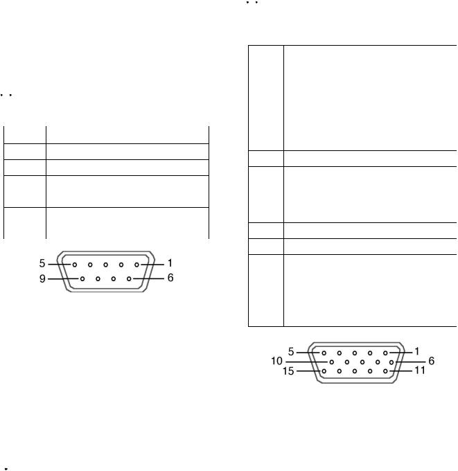
ACC (Accessory I/O)
ACC connector pinouts are listed below.
 ACC is not a VGA video connector. The K3S does not provide a video output. (The P3 does have an SVGA video output option; see pg. 47.)
Pin # |
Description |
1 |
FSK IN (see FSK Input) |
2AUXBUS IN/OUT (see KRC2 or XVSeries transverter instruction manual)
3 |
BAND1 OUT (see Band Outputs) |
4 |
PTT IN (in parallel with MIC PTT) |
5 |
Ground (RF isolated) |
6 |
DIGOUT0 (see Transverter Control) |
7K3S ON signal (out) or TX INH (in) (see Transverter Control, TX INH)
8 |
POWER ON (see pg. 46) |
9 |
BAND2 OUT (see Band Outputs) |
10 |
KEYOUT-LP (10 mA keying output) |
11 |
DIGOUT1 (see DIGOUT1) |
12 |
Ground (RF isolated) |
13 |
BAND0 OUT (see Band Outputs) |
14 |
BAND3 OUT (see Band Outputs) |
15EXT ALC input (see External ALC, pg. 29)
ACC Connector (female, on KIO3B panel)
FSK Input (for FSK D Data Mode)
This is a TTL input pulled up to 5V, compatible with PC outputs. When used with an RS232 signal from the PC, a level translator is required.
DIGOUT 1
DIGOUT1 is a per-band/per-antenna output for controlling external gear. See CONFIG:DIGOUT1.
20
Band Outputs (BAND0-BAND3)
BAND0-BAND3 are open-drain band selection outputs, with internal pull-up resistors to 5 V. Their behavior is controlled by CONFIG:KIO3B (see below). Band data is based on VFO A’s frequency.
In tables below, 0 = pulled to ground (0 V). 1 = floating to 5 V. External pull-up resistors can be connected a voltage not exceeding 14 V.
With CONFIG:KIO3B set to N O R , the BAND0-3 outputs are mapped based on the selected HF-6 m band as shown below. On transverter bands, BAND0-3 will all be set to zero.
Band |
BAND3 |
BAND2 |
BAND1 |
BAND0 |
160 m |
0 |
0 |
0 |
1 |
80 m |
0 |
0 |
1 |
0 |
60 m |
0 |
0 |
0 |
0 |
40 m |
0 |
0 |
1 |
1 |
30 m |
0 |
1 |
0 |
0 |
20 m |
0 |
1 |
0 |
1 |
17 m |
0 |
1 |
1 |
0 |
15 m |
0 |
1 |
1 |
1 |
12 m |
1 |
0 |
0 |
0 |
10 m |
1 |
0 |
0 |
1 |
6 m |
1 |
0 |
1 |
0 |
If CONFIG:KIO3B is set to T R N , BAND0-3 reflect the parameters of the CONFIG:XVn ADR menu entry, as shown below. On HF-6 m they’re set to 0. Addresses INT . TRN0 - 9 are used with the internal 2-m transverter option (K144XV). INT TRN0 sets all band outputs to 0, while INT
TRN1 - 9 have the same decodes as TRN1 -9 .
Transverter addresses are also sent to Elecraft XVseries transverters and the KRC2 band decoder accessory via the AUXBUS line. Note: TRN1 - 7 are sent as 1-7, but TRN8 - TRN9 are sent as 0.
ADR |
BAND3 |
BAND2 |
BAND1 |
BAND0 |
T R N 1 |
0 |
0 |
0 |
1 |
T R N 2 |
0 |
0 |
1 |
0 |
T R N 3 |
0 |
0 |
1 |
1 |
T R N 4 |
0 |
1 |
0 |
0 |
T R N 5 |
0 |
1 |
0 |
1 |
T R N 6 |
0 |
1 |
1 |
0 |
T R N 7 |
0 |
1 |
1 |
1 |
T R N 8 |
1 |
0 |
0 |
0 |
T R N 9 |
1 |
0 |
0 |
1 |
With CONFIG:KIO3B set to HF -TRN , the BAND0-3 outputs follow the NOR table when HF- 6 m bands are selected, and the TRN table when a transverter band is selected.
Transverter Control
Normally, when the K3S is turned on, a 5-VDC logic signal appears on ACC pin 7 (K3S ON). This could be used with Elecraft XV transverters as an enable signal (pin 8 of J6 on the transverter).
However, pin 7 can alternatively be configured as a transmit inhibit input line for use in multitransmitter stations. (See TX INH, below.) In this case it is not available as a power-on signal for Elecraft transverters. Instead, the transceiver’s 12VDC switched output could be used as a transverter ON signal.
For transverter keying, you can use KEYOUT-LP signal (pin 10 of the ACC connector) or the KEY OUT jack (RCA).
With KIO3B set to TRN or HF -TRN , the DIGOUT0 line (ACC, pin 6) will output 0 V when low power mode is selected for the current transverter band (CONFIG:XVn PWR). At all other times, DIGOUT0 will be floating (Hi-Z).
TX INH (Transmit Inhibit Signal)
Pin 7 of the ACC connector can be configured as a transmit inhibit input by setting CONFIG:TX INH to LO=Inh (or HI=Inh ). Holding pin 7 low (or high) will then prevent transmit. An external 2.2 to 10 K pull-up resistor (to 5 VDC) is required.


 If TX INH is set to OFF , pin 7 reverts to its default output function, K3S ON (see above).
Elecraft KRC2 Universal Band Decoder
An Elecraft KRC2 can be used with the K3 to perform station switching functions; it includes sink and source relay drivers for all bands. The KRC2 obtains band data via the AUXBUS rather BAND0- 3. (See CONFIG:KRC2 for 6-m band mapping). Refer to the KRC2 instruction manual for more information.
21

SPKRS
STEREOΩ or MONO; 4 to 8
Plugging in external speaker(s) cuts off the internal speaker. A stereo plug is recommended; tip is left speaker, ring is right. If you must use a mono plug, set CONFIG:SPKRS to 1 to disable right-channel audio. (This will result in mono headphone output, as well, if you also set SPKR+PH to Y E S .)
 If the speaker is not working with headphones unplugged: Locate the CONFIG: SPKR+PH menu entry. Tap
  1
1 on the numeric keypad until you see PH .R SW – (specifying inverted logic for the rear headphone jack). This is the default setting, required for the K3S.
PHONES
STEREOΩminor.recommendedMONO;16
The front and rear-panel headphone jacks are both isolated with series resistors. This allows you to use mono phones on one jack and stereo on the other, if required. You’ll need stereo phones for AFX (audio effects) and stereo dual receive (with sub receiver).
 You can plug in headphones and speaker(s) at the same time, and hear audio in both, if you set CONFIG:SPKR+PH to YES . However, if you set
CONFIG:SPKRS to 1 , setting SPKR+PH to YES will result in mono output for both headphones and speakers. You can set SPKRS to 2 if you use a stereo plug at the external speaker jack, or if no external speaker is plugged in.
MIC
MONO; hior low-Z
This jack accommodates an electret or dynamic mic. Use MAIN:MIC SEL to select the rear panel mic (RP ). Tap  1
1 to turn on Low or High mic gain range. Tap
  2
2 to turn bias on/off (see pg. 30 for recommendations based on mic type).
For the front-panel mic only, additional microphone gain can be enabled by tapping  7
7 . Use this only for very low-output mics. Not required for use with the Elecraft MH2.
If the rear-panel mic has a PTT line, it can be connected to either the PTT IN jack or the PTT input on the ACC connector (pg. 20).
LINE IN
MONO, transformer-isolated;Ω(nominal)600
The LINE IN jack on the K3S can be connected to your computer’s soundcard output. (It is preferable in most cases to obtain line-in audio via the USB cable. See pg. 18.)
If a plug is inserted into LINE IN at the K3S, this line input will override the USB port’s line-in.
The 
 M I C
M I C gain control on the K3S sets the line input level when the MAIN:MIC SEL menu entry is set to LINE IN .
 The LINE IN level should be set carefully to avoid transmit signal distortion due to saturation of the input audio transformer. In addition, computer sound card gain should be set 6 to 10 dB below the level at which the sound card’s output stage starts clipping.
LINE OUT
STEREO, transformer-isolated;Ω(nominal)600
LINE OUT can be connected to your computer’s soundcard inputs. (However, this is not necessary if you’re using the USB port for line-level audio.) Normally, the left channel is main receiver audio, and the right channel is sub receiver audio (if applicable). In this case the outputs are post-AGC but pre-AF-gain.
Use CONFIG:LIN OUT to set the level, or to switch from a fixed-level setting to =PHONES .
 LIN OUT settings above 10 are usually not necessary. This can in some cases cause overloading of either the output transformers in the K3S or the PC soundcard inputs (typically on noise peaks). Either could degrade the performance of demodulation software.


 Some computers have only very high-gain, high-impedance microphone inputs, not line-level inputs. This can make it difficult to adjust the LINE OUT level, and can also worsen noise pickup. If a high-impedance mic input must be used, you can add a resistive attenuator between the K3S and the mic input to improve signal-to-noise level.
22

Basic Operation
This section covers the fundamentals of K3S receive and transmit operation. It’ll also get you started using each of the major operating modes.
Once you’re familiar with the K3S, please go on to
Advanced Operating Features (pg. 35).
Using Tap/Hold Switches
Most K3S switches have two functions. Tapping (pressing for less than 1/2 second) activates the function labeled on the switch. Holding (pressing for more than 1/2 sec.) activates the function labeled beneath the switch.
Initial Power-Up
•Connect a power supply (pg. 8); antenna or dummy load; key, if used (pg. 16); mic, if used, and station ground (pg. 16).
•Tap  P O W E R
 to turn the K3S on. The LCD should illuminate and show VFO A and B
frequencies. (Tapping  P O W E R
 again turns power off.)
•The VFO B display can show a variety of useful parameters in addition to the normal
frequency display. To see these, tap  D I S P
 (left of the display), then rotate the VFO B knob. The VFO B display will cycle through time, date, RIT/XIT offset, supply voltage, current drain, etc. (pg. 38). You can use these displays to make sure the supply voltage is in range (1115 V), and that current drain is about 1 amp (higher with sub receiver installed and turned
on). Tap  D I S P
 to return to the normal VFO B frequency display.
Using the Menus
There are two menus: M A IN and C O N F IG . Most entries in the CONFIG menu are used for test, configuration, and alignment, and are used infrequently.
Nearly all menu entries appear in alphanumeric order. In the few exceptions to this, adjacent entries are still closely related.
MAIN Menu
•Tap  M E N U
 to access the main menu. (Tapping
  M E N U
 again exits the menu.)
•Use VFO B to scroll through the menu entries, referring to the list on pg. 55 for details.
•Change the value (or parameter) of any menu entry using VFO A.
CONFIG Menu
•Hold C O N F I G (hold function of the  M E N U
 switch) to access the CONFIG menu. Holding CONFIG for 3 seconds enters TERMinal mode (for use with the K3/0-Mini panel; see pg. 47).
•Use VFO B to scroll through the CONFIG menu entries, referring to the list on pg. 57.
Menu Help
While in the menu, tapping  D I S P
 shows help information about the present menu entry. For most entries, the default parameter value is shown in parentheses at the start of the help text.
Programmable Functions
Menu entries that you’d like quick access to can be assigned to any of the 10 programmable function switches, P F 1 , P F 2 , and  M 1
M 1 –
–  M 4
M 4 (tap or hold). “F u n c tio n ” menu entries can only be used via such a switch assignment. (Examples, from the CONFIG menu: VFO B->A and TTY LTR.)
To set up a programmable function switch, first use  M E N U
 or C O N F I G to locate the target menu entry. Next, hold P F 1 or P F 2 ; or, tap or hold
  M 1
M 1 –
–  M 4
M 4 . For example, if you tap
  M 2
M 2 , you’ll see M2T SET (T for tap), while holding
  M 2
M 2 would show M2H SET (H for hold). The assigned switch can then be used as a shortcut to access that entry.
  M 1
M 1 –
–  M 4
M 4 can each be assigned a tap and/or hold function.
 Any
Any  M 1
M 1 –
–  M 4
M 4 switch that is used as a programmable function switch will not be available for message play. To cancel a programmable switch assignment and restore a previously-saved message, tap
  R E C
R E C , then tap the buffer you’d like to restore
( M 1
M 1 –
–  M 4
M 4 ), then tap
  R E C
R E C again.
Macros
Programmable switches can also be used to automate often-used sequences, or macros, such as “SPLIT, A>B, move VFO B up 5.” Refer to the CONFIG:MACRO x menu entry, K3 Utility help, or the K3 Programmer’s Reference.
23

Band and Mode Selection
Tap either end of  B A N D
 to select the desired ham band (160 through 6 meters). You can use direct frequency entry (pg. 15), or recall a frequency memory (pg. 16). Individual bands can be mapped out if not needed (see CONFIG:BND MAP).
Tap either end of  M O D E
 to select the operating mode. Hold A L T to select an alternate mode, if required. This include CW REV (pg. 32), DATA REV (pg. 33), AM -S (synchronous detection, pg. 31), and FM +/- (FM repeater split, pg. 31).
Antenna Selection and Matching
Main Antennas (ANT1 and ANT2)
With a KAT3A ATU installed, you can connect antennas to both ANT1 and ANT2; tap  A N T
A N T to select. Holding A T U selects AUTO (autotune enabled) or BYPASS mode. In AUTO mode (ATU icon on), the antenna can be matched for best SWR by tapping
  A T U T U N E
 . Up to 30 ATU settings are saved for both antennas. See CONFIG: KAT3 for instructions on clearing ATU memories.
The ATU icon will flash briefly whenever new settings are automatically loaded.
 Tapping
  A T U T U N E
 a second time within 5 seconds starts a more extensive match search. The ATU can even be manually tuned if desired. Refer to CONFIG:KAT3A for details.
 Holding
  A N T
A N T allows names to be assigned to ANT1 and 2 (e.g., ‘YAGI’). These will be flashed when you switch antennas. When editing names, VFO B selects the character position to change; VFO A cycles through available characters. Setting the first character to “-” disables name display.
Receive-Only and 2-Meter Module Antennas
Tap  R X
R X to select the receive-only antenna (RX ANT IN/OUT on the KXV3B module, pg. 41). The KRX3A sub receiver either shares the main receiver’s selected antenna or uses an auxiliary input (see AUX RF, pgs. 39 and 43).
If a K144XV 2-meter module is installed, connect its antenna to ANT3. (See K144XV manual.)
Automatic control of a KAT500 ATU
The K3S can automatically recall settings for a connected KAT500 ATU as the VFO is tuned. See CONFIG:KAT3A and the KAT500 owner’s manual.
Using the VFOs
VFO A is both the main receive and transmit frequency, except during SPLIT, in which case VFO B controls the transmit frequency (pg.38). VFO B also controls the sub receiver (pg. 39).
Tap  R A T E
 to select 10 / 50 Hz per step. The faster rate can be changed using CONFIG:VFO FST. The number of counts (or steps) per VFO knob turn can be changed using CONFIG:VFO CTS. Tapping
  R A T E
 briefly flashes either the 10-Hz or 100-Hz digit to indicate slow or fast tuning.
For 1-Hz steps, tap  F IN E
 ; for wider steps, use
C O A R S E (CONFIG:VFO CRS sets coarse steps per-mode). When  F IN E
 is in effect, a 1-Hz digit will appear in the VFO A display. When C O A R S E is in effect, the 10-Hz digit is not shown.
Tap  A
A  B
B once to copy VFO A’s frequency to VFO B. Tapping
  A
A  B
B a second time within 2 seconds also copies VFO A’s filter setup, preamp state, and other settings to VFO B.
 A / B
A / B exchanges VFO A and B and their settings.
(Also see CONFIG:VFO B->A.) Pressing  R E V
R E V only exchanges the VFOs for as long as you hold it in. (Exception: When using an FM repeater offset,
  R E V
R E V permanently swaps RX/TX.)
VFO B and the sub receiver can be set up directly by holding B S E T . While BSET is in effect, all icons and VFO-related controls apply to VFO B (and to the sub receiver, if turned on; see pg. 39).
Holding S U B turns on diversity mode (pg. 39).
RIT and XIT
The RIT/XIT offset control, at the far right, sets the offset for  R IT
R IT and
and  X IT
X IT . The offset is shown on the VFO B display as you adjust the control. Three LEDs show whether the offset is 0, (-) or (+).
Tap  C L R
C L R to zero the RIT/XIT offset. Tapping it a second time restores the offset.
To copy the present RIT offset to VFO A, hold
 C L R
C L R for 2 seconds. VFO A will be moved to the new frequency before the offset is zeroed.
 If RIT/XIT are both off, the offset control can coarse-tune VFO A (CONFIG: VFO CRS). Coarse tuning steps are programmable by mode.
24
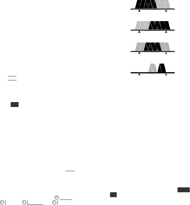
Receiver Setup
This section explains how to use basic receiver controls. Setup for specific operating modes is described in later sections; see Voice Modes (pg. 30), CW Mode (pg. 32), and Data Modes (pg. 33).
Also see Text Decode and Display (pg. 35) and Audio Effects (pg. 37).
Receiver Gain Controls
Use  AF — S U B (pg. 11) to set the desired main and sub receiver volume level. There are two overall audio volume ranges, LO and HI, which can be selected using CONFIG:AF GAIN.
Usually, both  RF — S U B controls will be set fully clockwise (main and sub receiver RF gain). You may wish to reduce RF gain to optimize receiver response to high signal levels or noise.
 If sub RF gain has been configured as squelch for both receivers, then main RF gain will control RF gain for both. (See CONFIG:SQ MAIN.)
Preamp and Attenuator Controls
Tap  P R E
P R E to turn on preamp 1 (+10 dB). On 12-6 m, a second tap turns on preamp 2, a +20 dB, ultra low-noise preamp for weak-signal work. The P R E icon flashes when preamp 2 is selected. Use CONFIG:PREAMP2 to enable preamp 2.
Hold A T T to turn on the attenuator. The main receiver has 5/10/15 dB settings, selectable perband via the MAIN:ATTEN menu entry. (Holding the ATT switch for over 2 seconds also takes you directly to this menu entry.) The sub RX has a 10dB attenuator, switchable in BSET mode (pg. 39).
Crystal Filter Selection
You can install up to five crystal filters in the main and sub receivers. For diversity receive, matched filters should be used (pg. 40). Bandwidths as narrow as 200 Hz are available. See Appendix A for recommended filter bandwidths for each mode.
To select a crystal filter manually, tap  X F I L
 . The F L 1 -F L 5 icons show the current selection. This sets the DSP passband to match the crystal filter,
and removes any passband shift or lo cut/hi cut. The K3S will also select appropriate crystal filters
automatically as you adjust the |
S H I F T , |
|
W I D T H , |
L O C U T , and |
H I C U T controls. |
Filter Passband Controls
As you rotate the filter controls (shift, width, lo cut, hi cut), the associated parameter value is shown on VFO B. The filter graphic shows the width and location of the passband, as illustrated below. In these specific examples, segments that turned off as a result of control movement are shown in gray.
High Cut
Low Cut
Width
Shift
 Filter passband controls don’t apply in FM mode. SHIFT control granularity can be set to either 10 or 50 Hz in CW and DATA modes; see CONFIG:PB CTRL. In Sync AM mode (A M - S ), SHIFT selects the upper or lower sideband.
Each passband control has an integral switch. These switches are used as follows:
Tapping the control alternates between the two primary functions for that control, for example HI CUT and WIDTH. This is indicated by the two LEDs above each control.
Holding a control activates its secondary function, labeled below the control.
 Tapping or rotating a control shows the present setting. To see the settings of both knob functions without changing them, just tap the control twice.
The secondary functions of the controls are N O R M and I / I I , described in the following sections.
25

Filter Presets (I/II)
Each operating mode provides two “floating” filter presets, I and II, which store filter settings on a per-VFO, per-mode basis (excluding FM). They are updated continuously as you change filter settings. Fixed (non-floating) per-mode filter settings are also available, as explained below.
You can alternate between the I and II settings by holding the I / I I switch. This is especially useful when you’re alternating between wide and narrow settings during contest or DX operation.
Filter Normalization (NORM)
Standard Settings
To get quickly to a standard per-mode bandwidth and reset any passband shift or cut, hold N O R M (normalize). The normalized AF bandwidth is 400 Hz in CW and DATA modes, 2.7 or 2.8 kHz in SSB modes, and 3.0 kHz for AM1.
 Whenever you normalize the filter passband, two small "wings" appear at the left and right ends of the DSP filter passband graphic as shown below.
Moving any DSP control makes the "wings" disappear, as a reminder that the passband is no longer normalized.
1 In AM mode, the I.F. bandwidth required for good fidelity is about twice the AF bandwidth. This is why a 6 kHz or wider crystal filter is needed to effectively use the 3 kHz NORM setting. If an FM filter is installed, it can be used in AM mode to provide good fidelity at even higher AF bandwidth settings.
Custom Settings (NORM1 and NORM2)
In addition to the standard "NORM" values, you can save two of your own setups in each mode, then recall them using the N O R M function. These setups are referred to as NORM1 and NORM2.
To save a custom normalization setting:
•set up the filter passband as desired for the current mode
•hold N O R M until you see < - SAV - > (3 seconds)
•rotate the knob slightly left or right to save it as
NORM1 or NORM2 .
(The arrows to the left and right of SAV are a reminder that you can rotate the knob to get to the two user-defined normalization settings.)
To recall, hold N O R M until you see < - NOR - > (about 1/2 second), then rotate the knob left or right to recall NORM1 or NORM2 .
Narrow DSP Filter Selection
For bandwidth settings of 100 Hz or lower, the DSP normally uses a type of filter that minimizes ringing: the Finite Impulse Response or FIR filter.
If you’d like steeper filter skirts, and don’t mind a small amount of ringing, you can select Infinite Impulse Response” or IIR filters for these bandwidths. Locate CONFIG:FLx BW menu entry, then tap  7
7 until you see IIR ON . Both main and sub receivers will use the same setting.


 IIR filters take longer to change from one bandwidth to another, so you may hear audio artifacts when adjusting the DSP controls. If this is objectionable, use the default FIR filters.
 Another narrowband filter alternative in CW mode is APF (audio peaking filter). This filter has a very narrow peak (~30 Hz) but very little ringing due to its broader skirts. See A P F , pg. 32.
26

Reducing Interference and Noise
The K3S provides several ways to cut interference, including DSP noise reduction, manual and auto notch, and noise blanking. Also see Audio Effects ( A F X
A F X , pg. 37).
There are actually two noise blankers: one at the first I.F. (KNB3 module), and the other at the 2nd I.F. (DSP).
 Noise reduction, noise blanking, and notch filtering should only be used when necessary. These signal processing techniques are very effective, but can introduce side effects. Sometimes, reducing the filter bandwidth is the most effective interferencereduction strategy.
Noise Blanking
Tap  N B
N B to enable I.F. and/or DSP noise blanking.
Next, hold L E V E L to set the DSP level (VFO A) and I.F. level (VFO B). You’ll initially see DSP OFF and IF OFF on the VFO A and B displays.
Rotating VFO A clockwise will turn on the DSP NB, showing DSP t1 -1 through DSP t3 - 7 . The first number shows the relative pulse integration time, and the second shows the blanking level. The higher the numbers, the more aggressive the DSP blanking action.
Rotating VFO B clockwise will turn on the IF NB, showing IF NARn , IF MEDn , or IF WIDn , where n is 1 -7 . NAR /MED /WID refers to narrow/ medium/wide blanking pulse widths, and n is the blanking level. Higher n means more aggressive blanking action. Use NAR width when possible to minimize strong-signal interaction effects.
 The NB icon will flash slowly if the I.F. blanker setting is too high for the present signal conditions. If this happens, use a lower setting.
Both the DSP and IF blanking settings are saved on a per-band basis. If CONFIG:NB SAVE is set to YES , the on/off status of  N B
N B will be also be saved for each band.
 The DSP noise blanker is in the 2nd I.F., where it can’t be activated by signals outside the crystal filter passband. It can be used with high-duty-cycle and complex-waveform noise generated by computers, switching power supplies, light dimmers, etc. The I.F. noise blanker is in the 1st I.F., where it can use very narrow blanking widths. It is most effective at blanking AC line noise, lightning, and other very broadband noise. Often, a combination of the two is the most effective.
Noise Reduction
Noise reduction reduces random background noise while preserving meaningful signals. It adds a characteristic “hollow” sound to all signals.
 N R
N R turns noise reduction on. It doesn’t apply to DATA or FM modes, or with AGC turned off.
Hold A D J to display the NR setting, which is saved per-mode. Use the VFO B knob to tailor NR for the present band conditions. In general, the higher the number, the more aggressive the noise reduction. Settings F1 -1 through F4 -4 are recommended. F5 -1 through F8 - 4 use a different algorithm, where the -x part of the setting indicates the degree of mix between the DSP-processed and unprocessed signals (-1 is about 50% processed, -4 is 100%). A small M appears to remind you that a M ixed setting is in effect, e.g. NR M F5 -1 .
Notch Filtering
Notch filtering removes interfering carriers while leaving the desired signal relatively unaffected. The K3S provides automatic and manual notch tuning.
Auto notch will find and remove one carrier, and in some cases more than one. (SSB mode only.)
Manual notch removes one carrier at a specified pitch, and can be used in CW and DATA modes as well as voice. Since manual notching sets up a fixed (rather than adaptive) notch, it can even suppress a keyed carrier, i.e. a Morse code signal.
Tap  N T C H
 to turn on notch filtering (NTCH icon). This turns on Auto notch in SSB mode, and Manual notch in other modes (adds
 icon).
Holding M A N U A L directly selects manual notch in any mode. Adjust the manual notch frequency using VFO B, then tap  N T C H
 again to exit.
27
 Loading...