

Elecraft KX3 Owner's Manual
ELECRAFT
®
KX3
ULTRA-PORTABLE
160-6 METER, ALL-MODE TRANSCEIVER
OWNER’S MANUAL
Revision C5, June 16, 2014
Copyright © 2014, Elecraft, Inc.
All Rights Reserved

2
Contents
Introduction .................................................... 3!
Key to Symbols and Text Styles ..........................3!
Installation ...................................................... 4!
Operating Position ...............................................4!
Power Supply .......................................................4!
CW Key/Keyer Paddle ........................................4!
Headphones and Speakers ...................................5!
Microphone ..........................................................5!
Computer/Control Port (ACC1) ..........................5!
Keyline Out and GPIO (ACC2) ...........................5!
Quadrature Outputs (RX I/Q) ..............................5!
Antennas ..............................................................6!
Grounding and ESD Protection ...........................6!
Control Panel Reference ................................ 7!
Display (LCD) .....................................................8!
Basic Operation ............................................... 9!
Getting Started .....................................................9!
Band Selection ...................................................10!
Mode Selection ..................................................10!
VFOs A and B ...................................................11!
Incremental Tuning (RIT and XIT) ...................11!
Special VFO B Displays ....................................11!
Receive Settings ................................................12!
Transmit Settings ...............................................14!
Transmit and ATU Control ................................14!
Voice Modes (SSB, AM, FM) ...........................15!
CW Mode ..........................................................16!
Advanced Operating Features ...................... 17!
Frequency Memories .........................................17!
Scanning ............................................................17!
Data Modes ........................................................18!
Text Decode And Display .................................19!
Programmable Function Switches .....................19!
Split and XIT .....................................................19!
Audio Effects .....................................................20!
Dual Watch ........................................................20!
Receive Audio Equalization (RX EQ) ...............20!
Transmit Audio Equalization (TX EQ) .............20!
SSB/CW VFO Offset .........................................21!
Digital Voice Recorder (DVR) ..........................21!
Transmit Noise Gate ......................................... 21!
Transmit Inhibit and External PTT ................... 21!
Cross-Mode Operation; CW-in-SSB ................ 21!
Transverter Bands ............................................. 21!
Special VFO B Displays ................................... 22!
Extended Single Sideband (ESSB) ................... 22!
Internal Batteries .......................................... 23!
VFO Friction Adjustment ............................. 24!
Options and Accessories ............................... 25!
Firmware Upgrades ...................................... 25!
SDR Applications .......................................... 26!
Remote Control of the KX3 ........................... 28!
Configuration ................................................ 29!
Option Module Enables .................................... 29!
Menu Settings ................................................... 29!
Calibration ..................................................... 31!
Reference Frequency ........................................ 31!
Receive Sideband .............................................. 32!
Transmit Bias .................................................... 32!
Transmit Gain ................................................... 33!
Transmit Carrier ................................................ 34!
Transmit Sideband ............................................ 34!
Menu Functions ............................................ 35!
Troubleshooting ............................................ 44!
Parameter Initialization (EEINIT) .................... 46!
Error Messages (ERR nnn) ............................... 47!
Theory Of Operation ..................................... 49!
RF Board ........................................................... 49!
Control Panel (CP) Board ................................. 50!
KX3 Block Diagram ......................................... 51!
Glossary of Selected Terms .............................. 52!
Specifications ................................................ 54!
Customer Service and Support ..................... 55!
Index .............................................................. 56!
3
Introduction
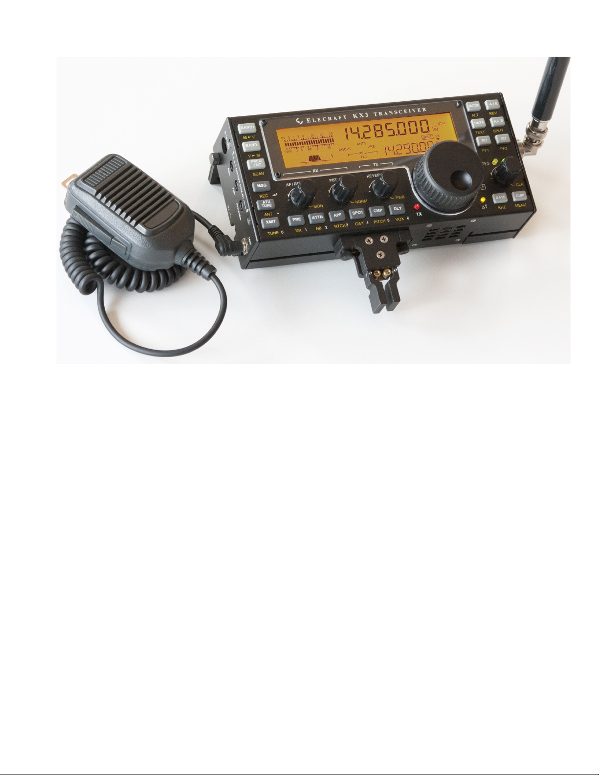
On behalf of our entire design team, we’d like to thank you for choosing the Elecraft KX3.
The KX3 is a compact, 160-6 meter, all-mode transceiver that’s ideal for both new and experienced
operators. Its unique features meet the requirements for home station use, portable, mobile, and even
hand-held operation.
Since the KX3 is a software-defined-radio (SDR), you’ll be able to extend its capabilities using
computer applications, and add new features via free firmware upgrades. But the KX3 is also the only
compact transceiver that combines the flexibility of an SDR with a full-size front panel and display,
allowing operation with or without a computer.
Despite its small size, the KX3 can be configured as a fully self-contained amateur station, with an
internal antenna tuner, battery charger, 2-meter or 4-meter module, and attached CW keyer paddle.
These options can be added at any time. Current drain is also very low for a full-featured transceiver,
reflecting our commitment to field operation. For mobile and home use, you can boost the KX3’s
output to 100 watts with the optional KXPA100 amplifier. Finally, there’s the PX3 high-performance
Panadapter, which enhances operation by allowing you to see signals even before you hear them.
When it’s time to take on the challenge and adventure of amateur radio, your KX3 will be ready.
73,
Wayne, N6KR
Eric, WA6HHQ
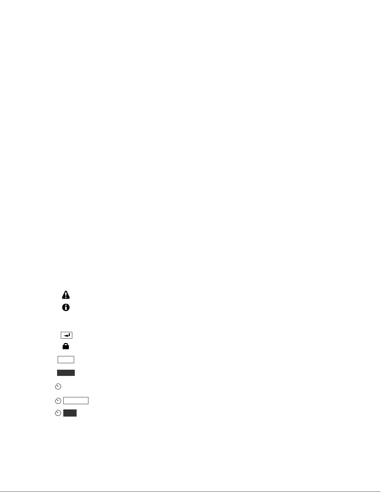
Key to Symbols and Text Styles
Important – read carefully
Operating tip
LSB
. .
Display icon or text
Enter keypad function
Lock indicator (applies to VFO or menu parameter)
XMIT
TUNE
MIC
Tap switch function (labeled on a switch)
Hold switch function (labeled below a switch; hold for about 1/2 second)
Function of a rotary control (knob)
OFS / B
CLR
Tap switch function of a rotary control (labeled above a knob)
Hold switch function of rotary control (labeled below a knob; hold for 1/2 second)
BKLIGHT
Menu entry
4
Installation
CAUTION
! Be careful when plugging in cables. Avoid
applying sideways pressure that might damage
the KX3’s left-side jacks.
! Avoid operating in wet conditions (rain,
snow, spray, etc.). The KX3 is not waterproof.
! Avoid operating at very high temperatures.
! The KX3 can be damaged by electrostatic
discharge (ESD). Prior to opening the case,
touch a grounded, unpainted metal surface.
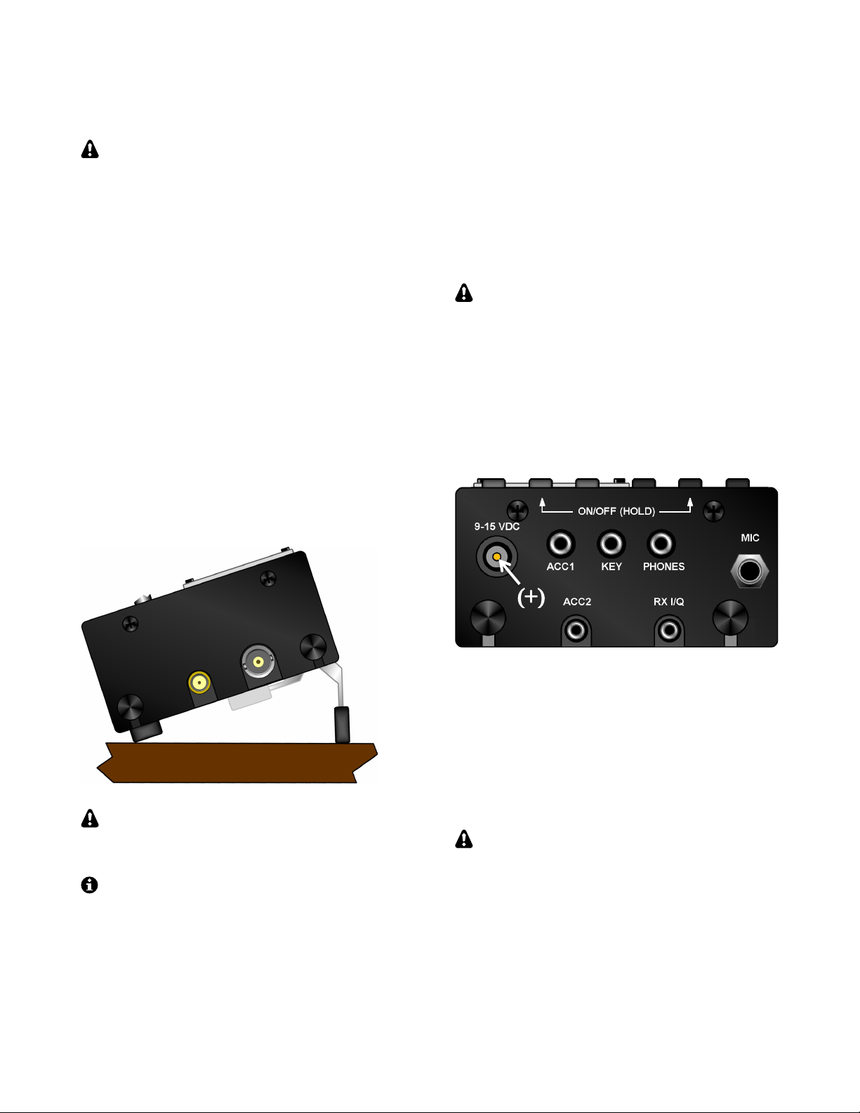
Operating Position
All controls are located on the top of the KX3’s
enclosure. This provides ample space for controls
and display, despite the transceiver’s small size.
Tilt legs are provided in the back to position the
controls and display for ease of use, as shown
below. Loosen the two rear thumbscrews before
adjusting the legs. Tighten them afterwards.
To open the enclosure, follow the
instructions on pg. 23 (Internal Batteries). Use
only the method shown.
The KX3 can be conveniently operated with
one hand, in a manner similar to writing in a
notebook. If you’re right-handed, rotate the radio
slightly counter-clockwise (see cover illustration).
If you’re left-handed, rotate the KX3 clockwise.
Power Supply
For fixed-station use, a low-noise 12-14 VDC
power supply or battery is recommended. (See
linear and switching power supplies in the
Glossary, pg. 52.) For lightweight portable
operation, the KX3’s internal 8-AA-cell battery
pack can be used. See Internal Batteries, pg. 23.
Maximum power output varies with supply
voltage and other parameters. For full power
(10+ watts on most bands), use 12-14 V.
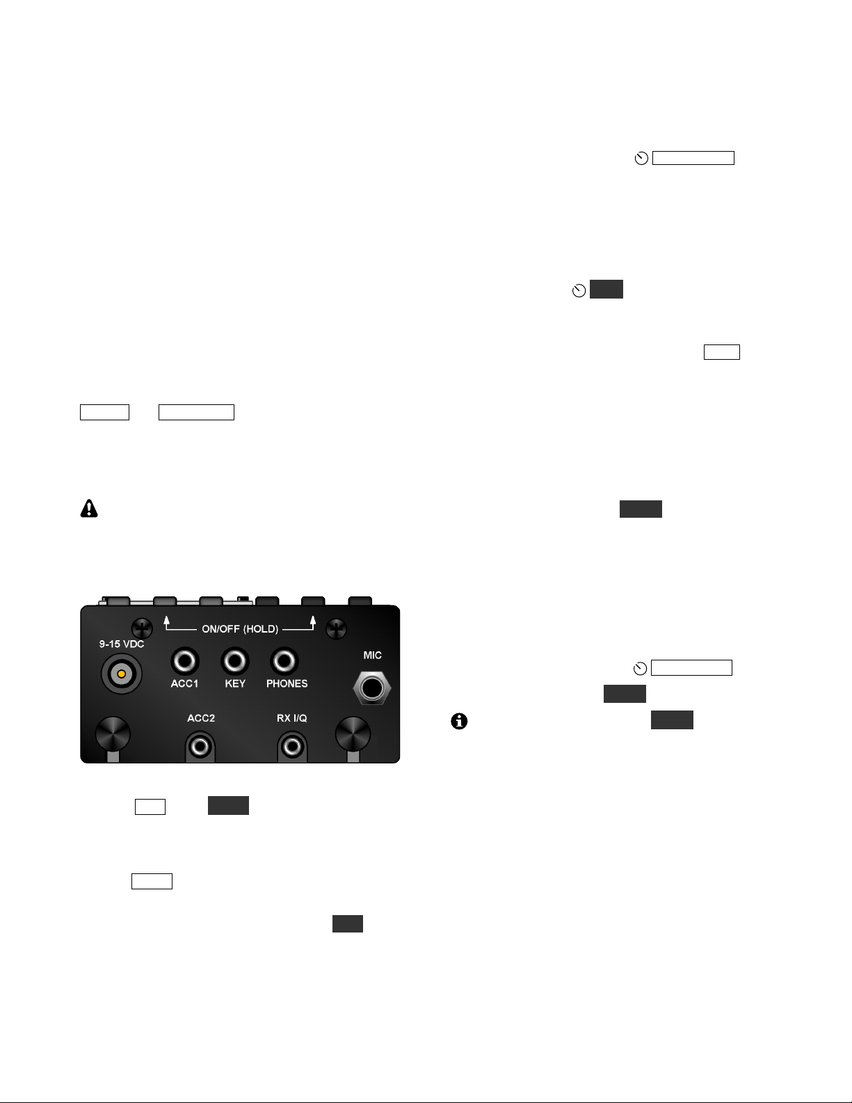
Connect an external power supply or battery to the
9-15 VDC jack (see illustration below). The center
pin is (+). A 2.1-mm power plug is required
(Switchcraft S760 or equivalent). On the supplied
power cable assembly, the wire with the white
stripe is (+). Trim the cable to the desired length.
CW Key/Keyer Paddle
The KX3 has two CW keying inputs:
KEY Jack: This stereo 3.5 mm jack on the left side
can be used with any hand key, keyer paddle, or
other keying device, as selected by the CW KEY1
menu entry (see Using the Menu, pg. 9).
A stereo plug is required at the KEY jack,
even if only the tip contact is being used, as with
a hand key.
KXPD3 Keyer Paddle: The KXPD3 is an optional
high-quality keyer paddle that attaches at the front
of the KX3 via two thumb screws. The dot and dash
paddles can be electrically reversed or configured
as a hand key using the CW KEY2 menu entry.
Allen wrenches are supplied for contact adjustment.
5
Avoid using bulky connectors or adapters
that could put excessive stress on side-panel
jacks. Lightweight cables, preferably with right-
angle plugs, are strongly recommended.
Headphones and Speakers
The 3.5-mm PHONES jack, on the left side panel,
accommodates mono or stereo headphones. You
can also plug in one or two amplified (or powered)
external speakers here. Mono or stereo plugs can be
used. Stereo allows the use of audio effects,
providing an enhanced listening experience (pg.
29).
The KX3 includes a small built-in speaker for use
in quiet operating environments. Plugging in
headphones disables the speaker and its amplifier.
(This is an easy way to extend battery life.)
Mobile installations: The interior of most vehicles
is too noisy for use with the KX3’s built-in speaker.
One or two amplified mobile speakers can be
plugged into the PHONES jack, or you can connect
this jack to your car stereo’s AUX input. Another
alternative is to use a device that retransmits the
KX3’s audio output in the FM broadcast band.
Microphone
The MIC jack is compatible with the Elecraft MH3
hand mic, which provides PTT as well as VFO
UP/DN buttons. For the MH3, set the MIC BIAS
menu entry to ON, and MIC BTN to PTT UP.DN.
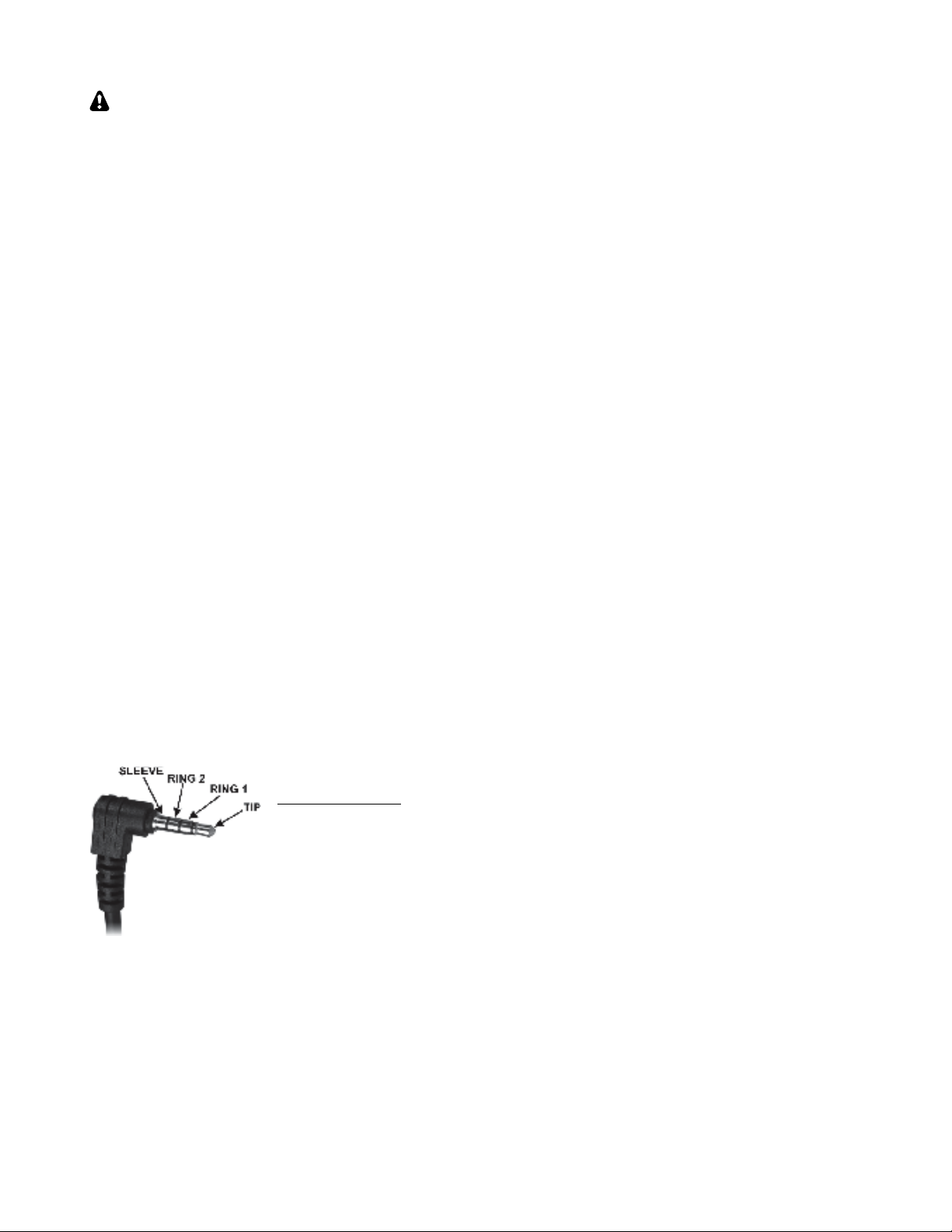
MH3 Mic Pinout
Sleeve: Shield
Ring2: Logic ground
Ring1: PTT/UP/DN
Tip: Mic audio
Using other microphones and headsets: The KX3
is compatible with many headset-mics that have
separate 3.5-mm plugs for mic audio and receive
audio. You can also use some “mini” mics intended
to plug directly into a laptop computer. Refer to the
MIC BIAS and MIC BTN menu entries to set up
the KX3 for use with your mic or headset.
Computer/Control Port (ACC1)
The 3.5-mm stereo ACC1 jack allows firmware
updates, configuration, and remote control of the
KX3 via a computer. The jack can be connected to
a computer’s USB port via the Elecraft model
KXUSB cable, or to an RS232 port via the model
KXSER cable. (The jack’s tip connection is RX
data from the computer. Ring is TX data to the PC.)
Elecraft provides two KX3 configuration programs:
KX3 Utility is required for KX3 configuration and
firmware updates (pg. 25). It also provides a
CW/data terminal function.
Our K3 Memory PC application can be used with
the KX3 to set up frequency memories more easily
than with the radio’s memory-store function.
Many logging, contesting, and control programs are
available from third parties. If the KX3 is not
specifically supported by a given program, try
selecting Elecraft K3 or K2.
Keyline Out and GPIO (ACC2)
The 2.5-mm stereo ACC2 jack provides a keyline
output (ring contact) and a general-purpose 3-volt
logic signal (tip contact).
The keyline output goes low during transmit, and
can be used for transmit/receive switching of linear
amplifiers and transverters. For keyline voltage and
current limits, see Specifications.
The general-purpose signal, GPIO, can be set up for
various equipment control functions. For example,
it can send band-change information to Elecraft
XV-series transverters. See the ACC2 IO menu
entry for a full list of uses for this signal, as well as
hardware interface requirements.
Quadrature Outputs (RX I/Q)
The 2.5-mm RX I/Q jack provides quadrature
outputs from the receive mixer (I=in-phase;
Q=quadrature, or 90 degrees out of phase). These
outputs can be used with the Elecraft PX3
Panadapter, as well as with computer-based
software-defined radio (SDR) programs, to extend
the capabilities of the KX3. See SDR Applications
(pg. 26).
6
Antennas
You can use any resonant antenna having a 50-ohm
(approximate) load impedance with the KX3.
Examples can be found in the ARRL Antenna
Handbook and other sources. A simple inverted “V”
or dipole can be very effective.
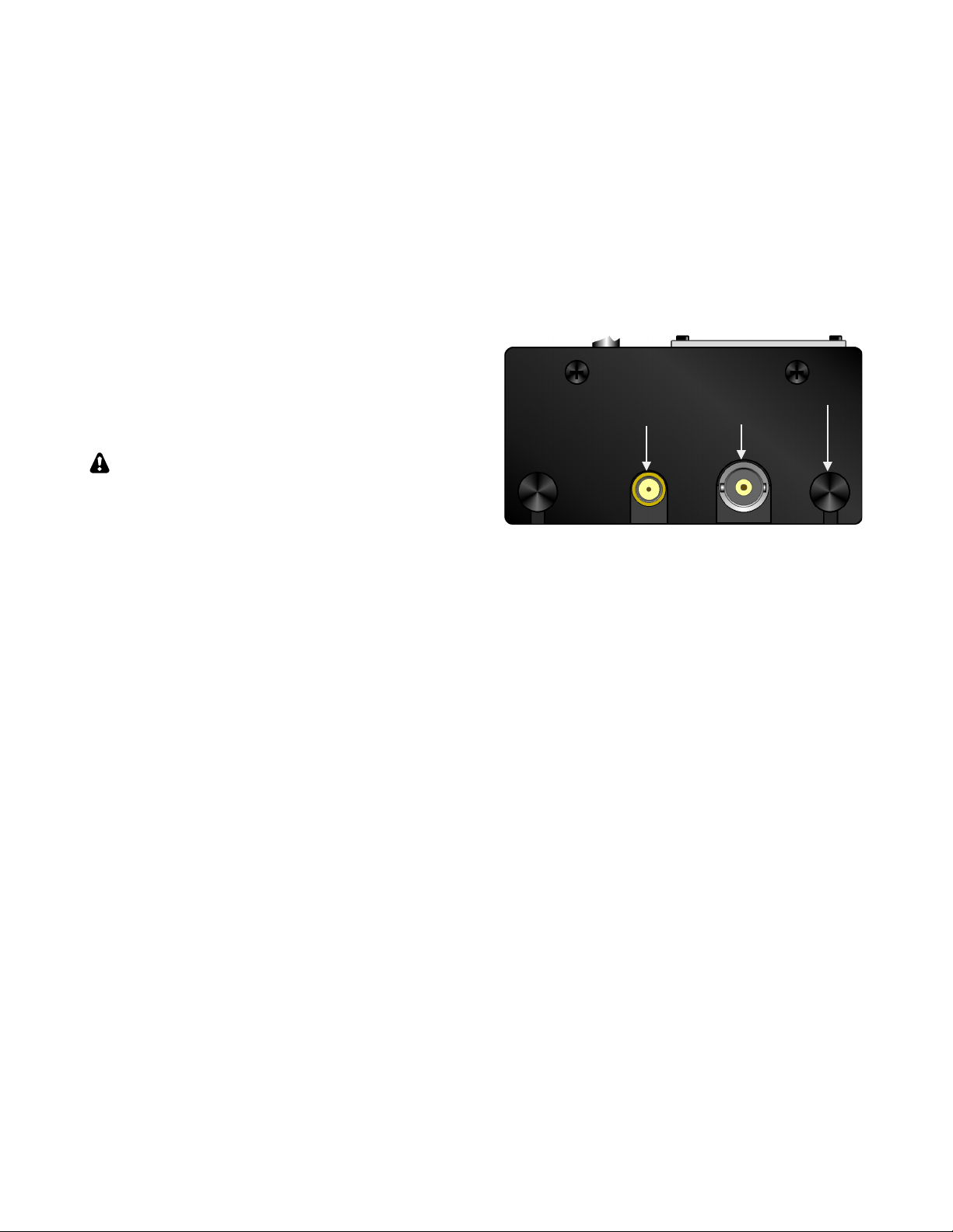
Antenna jacks: The BNC antenna jack, identified
at right, is used on 160-6 m. The SMA jack shown
is supplied with the KX3-2M/4M module (pg. 25).
The basic KX3 has a hole plug at this location.
Field Antennas: Field operation often calls for
non-resonant, ad-hoc wire antennas. For example,
you might use a single wire of 25’ (7 m) or longer,
tossed in a tree using a fishing weight or large hex
nuts. Another popular field antenna is the short,
loaded whip with interchangeable loading coils.
If you use a short whip, vertical, or a single
wire, a counterpoise of some kind is necessary
(described at right) to carry the return current. No
counterpoise is needed for a dipole, since one half
of the diplole carries return current.
SWR: One measure of how close an antenna is to
resonance is its SWR (standing wave ratio). The
KX3 displays SWR in TUNE mode (pg. 14). An
SWR of 1.0:1 (1.0-1 on the KX3’s display) is
considered a “perfect” match. To ensure safe
operation, the KX3 reduces power if SWR is high.
Using An Antenna Tuner (ATU): An ATU will
allow the KX3 to “see” a good match (i.e., a low
SWR) even with non-resonant antennas. This
allows the transmitter to deliver full power, and can
improve receiver sensitivity. An ATU may also
allow one antenna to be used on multiple bands.
You can use an external ATU (e.g., an Elecraft T1
or KXAT100) or internal (e.g., the KXAT3 option,
pg. 25). The KXAT3 stores matching information at
multiple points within each band.
Feedline: You can connect a wire antenna directly
to the KX3 without any coax or other feedline. (A
male BNC to binding-post adapter can be used,
such as Elecraft #BNC-BP.) However, many
antennas will function better when their feed point
is well above ground. A multi-band, random-length
antenna can be fed with twin-lead, then connected
to a balun (balanced-to-unbalanced converter, such
as the Elecraft BL1 or BL2), which in turn is
connected directly to the transceiver.
Grounding and ESD Protection
Connecting the chassis to a driven ground rod can
provide some protection against lightning and
damage due to electrostatic discharge (ESD). When
used in a building, the rod should also be bonded to
other building grounds. Connect the ground (or a
counterpoise for a whip or single-wire antenna) to
the KX3 at the thumb screw indicated below, on the
right side panel. The back thumb screw on the left
side can also be used.
Portable Station Ground: When you’re operating
from a temporary location, you can use one or more
radials as a counterpoise. This can simply be a set
of wires tied together at one of the KX3’s ground
points, then laid out on the ground in all directions.
When possible, use at least one 1/4- wavelength
radial for each band used. The length in feet can be
calculated from 234 divided by F, where F is the
operating frequency in MHz. If the wires are laying
on the ground, subtract about 20% from their
length. Random-length (untuned) counterpoise
wires can also be used when necessary.
Pedestrian Mobile Ground: The KX3 can be
operated hand-held—even while walking—with a
short whip antenna. Such antennas may provide
acceptable performance in receive mode without a
ground. However, if you plan to transmit, you’ll
need a trailing ground wire to serve as a minimal
counterpoise and greatly improve your transmitted
signal. This is true even if the KX3 indicates a low
SWR in TUNE mode (without a counterpoise, the
SWR reading can be misleading). 13’ is a good
choice for a trailing ground wire. This length is
about optimum on 20 meters, and is usable on 40-6
meters as well, assuming you’re using a multi-band
whip (or an antenna tuner). Small-diameter coax
such as RG-174 works well for a trailing wire
because it resists getting tangled while you walk.
2 m 160-6 m Ground
SMA BNC
7
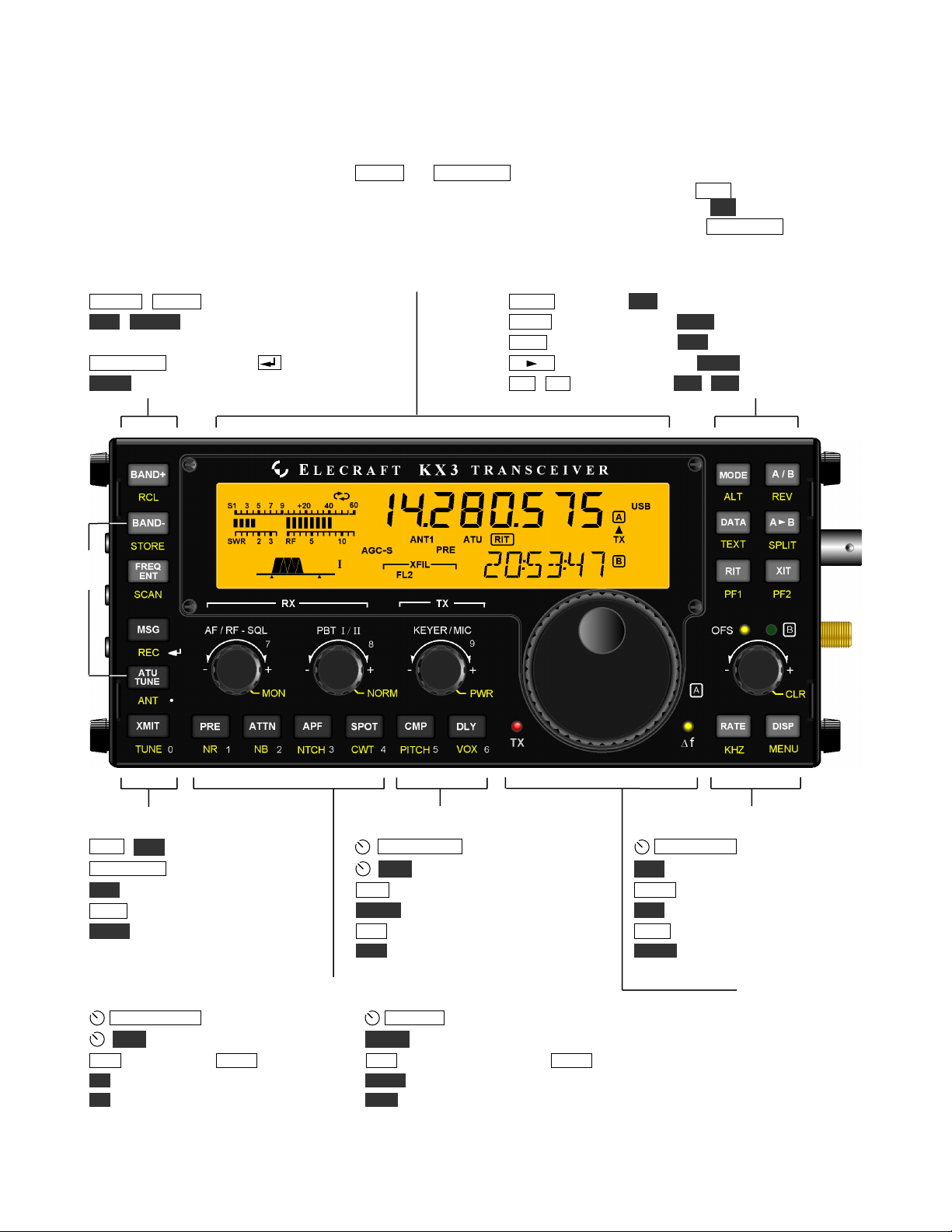
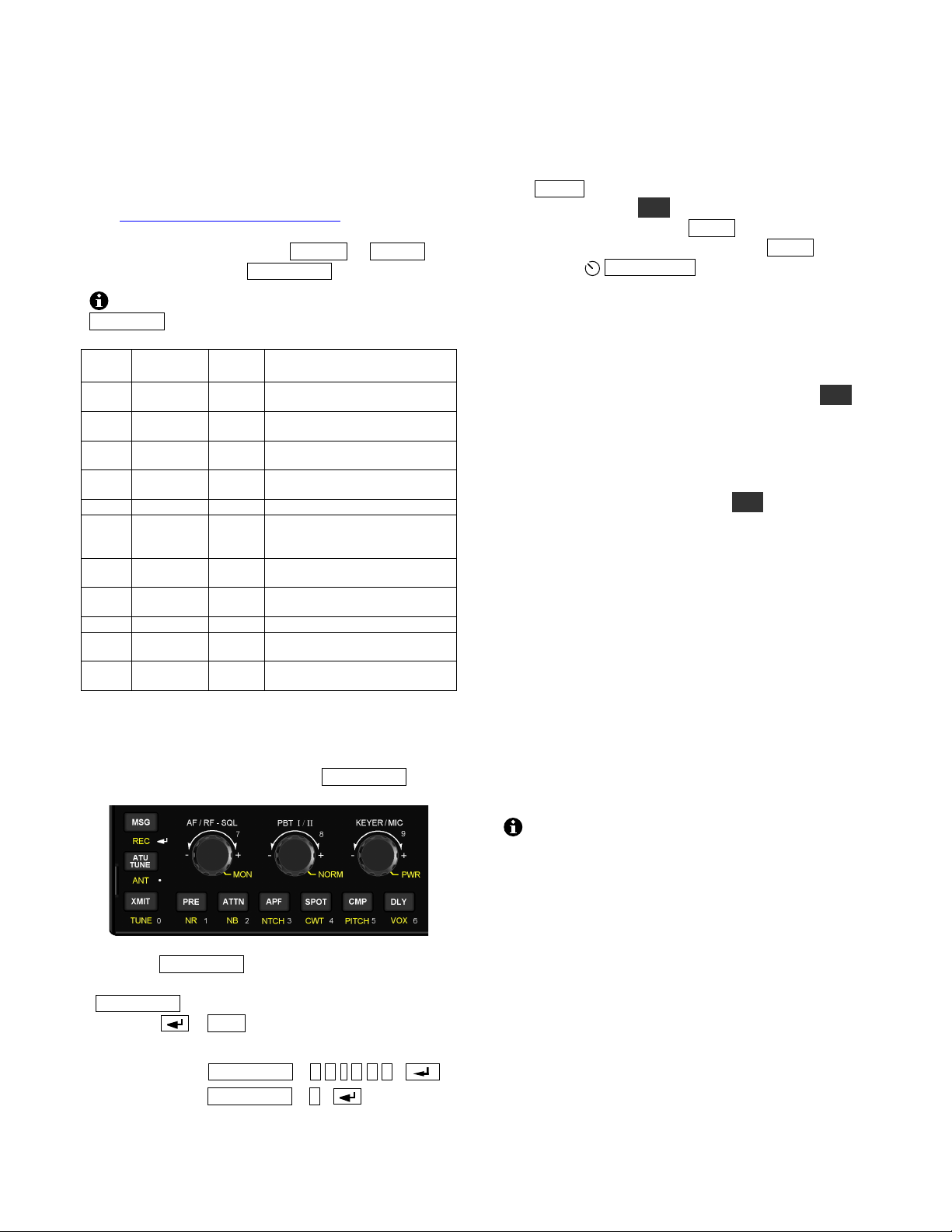
Control Panel Reference
This section summarizes all KX3 controls. For details, see Basic Operation and Advanced Operating Features.
To Turn Power ON/OFF: Hold both the BAND- and ATU TUNE switches for 2 seconds. (See ON/OFF label on left side.)
Tap Functions: Tap a switch or knob briefly to activate the function labeled on or above it, e.g. RATE .
Hold Functions: Hold the control for about 1/2 second to activate the function labeled below, e.g. KHZ .
Numeric Keypad: Switches and knobs at lower-left form a keypad (0-9/decimal/enter). Used with FREQ ENT, etc.
Band Selection Display, pg. 8 Operating Mode and VFO Setup
BAND+ / BAND- Band up/down, pg. 10 MODE Basic mode; ALT Alternate mode (e.g. LSB/USB), pg. 10
RCL / STORE Frequency memories, pg. 17 DATA Data submode, pg. 18; TEXT Text decode setup, pg. 19
per-band: tap 1-4; general purpose (00-99): use VFO A A / B VFO A/B swap, pg. 11; REV VFO/repeater reverse, pg. 11
FREQ ENT Use # keys, then ), pg. 10; DTMF, pg. 15 A B Copy VFO A to B, pg. 11; SPLIT Split RX/TX, pg. 19
SCAN Scan from VFO A to VFO B, pg. 17 RIT / XIT RX/TX offset, 11; PF1 / PF2 Prog. function, pg. 19
Transmit / ATU Control Transmit Settings Offset / VFO B and Misc.
MSG / REC Message play/record, pg 16 KEYER/MIC WPM, pg. 14; mic gain, pg 14 OFS/VFO B RIT/XIT/VFO B, pg. 11
ATU TUNE Start auto antenna tune, pg 14 PWR Set power level, pg. 14, 15 CLR Clear RIT/XIT offset, pg. 11
ANT Select ANT 1/2 (KXAT100 opt.), pg. 14 CMP Speech compression, pg. 15 * RATE Select 1/10 Hz VFO steps, pg. 11
XMIT Enter transmit mode (PTT), pg. 14 PITCH CW sidetone, pg. 16; FM tone, pg. 15* KHZ Select coarse VFO steps, pg 11
TUNE Transmit CW carrier at PWR level DLY CW QSK delay, pg. 16; VOX delay, pg. 16* DISP Show voltage etc. on VFO B, 11 *
(or MENU:TUN PWR level, if lower), pg. 14 VOX VOX/PTT (CW/voice separate), pp. 16, 15 MENU Use VFO B to select, A to edit
Receive Settings VFO A, pg. 11
AF / RF- SQL Receiver gain control, pg. 12 PBT I/II Passband tuning (I=WIDTH/LO, II=SHIFT/HI), pg 12 Transmit LED, pg. 14
MON Monitor & switch tones volume, pg. 12 NORM Filter passband normalization (per-mode), pg. 12 Delta-F LED, pg. 11
PRE Preamp, pg. 13 ; ATTN Attenuator, pg. 13 APF Audio peaking filter, pg. 13; SPOT CW spot tone, pg. 13
NR Noise reduction, pg. 13 * NTCH Autonotch (SSB) or manual notch (CW), pg. 13 *
NB Noise blanking, pg. 13 * CWT CW/DATA tuning aid (uses upper portion of S-meter), pg. 13
* To adjust the parameter for this switch function, use the knob immediately above the switch.
ON /
OFF
8
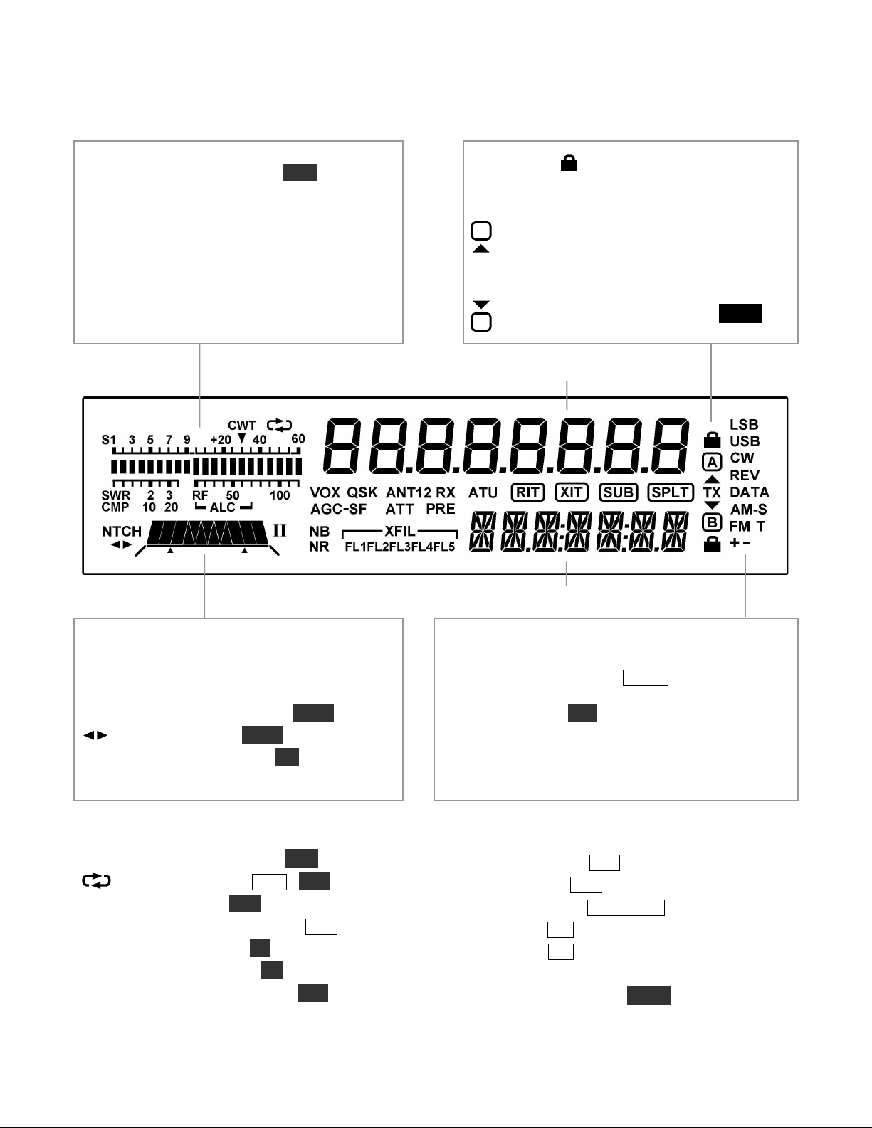
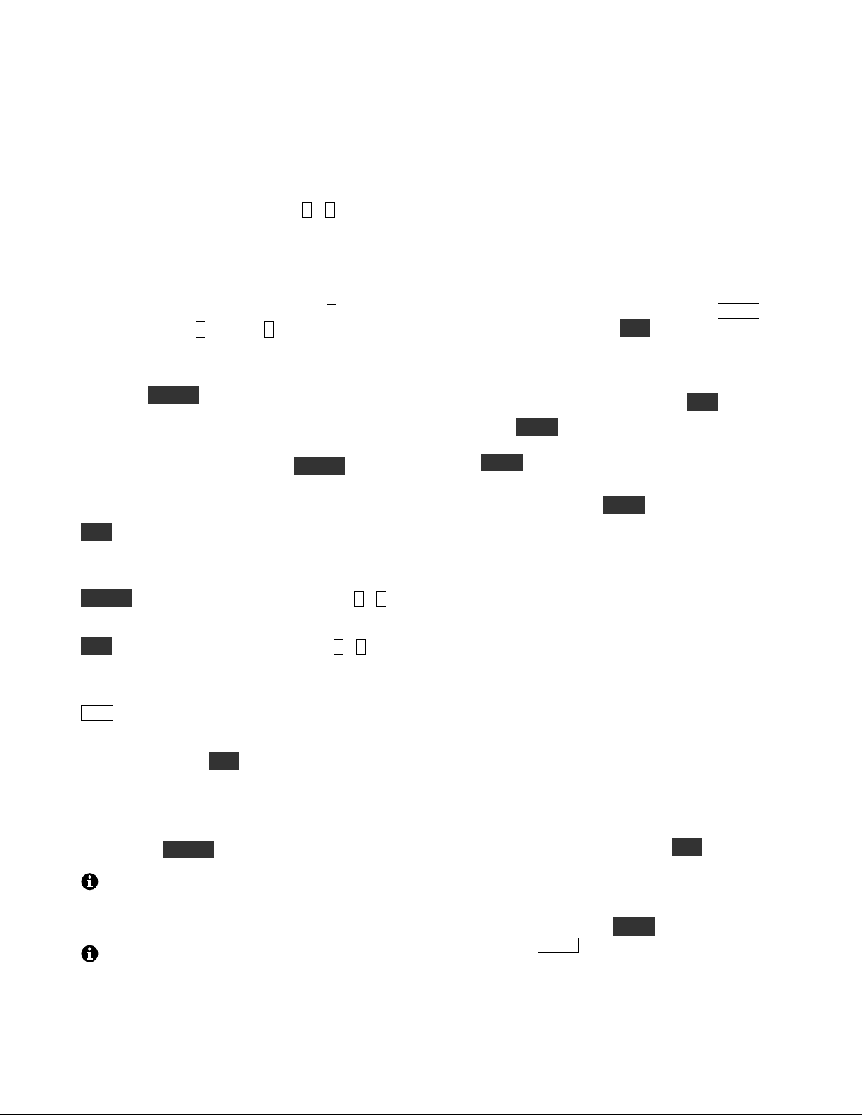
Display (LCD)
Bar graph, receive mode: Shows RX signal
strength in S-units (S-meter). If CWT is turned
on, the right half of the S-meter becomes a tuning
aid (pg. 13). Reducing RF gain adds a moving
reference segment (pg. 12).
Bar graph, transmit mode: Shows antenna
SWR and RF output (pg. 14). In voice modes,
shows CMP (compression) and ALC (mic level)
when mic gain or CMP are set (pg. 15). ALC
scale also used to set DATA audio level (pg. 18).
VFO Icons: Shows that a VFO or menu
entry is locked. The TX icon points to the transmit
VFO:
VFO A is the transmit VFO
VFO B is the transmit VFO; see
VFO A
VFO B
Filter Passband Graphic: Shows location
of receive filter passband (pg. 12)
Filter Icons:
NTCH Auto or manual notch (NTCH, pg. 13)
Manual notch (NTCH, pg. 13)
I / II PBT filter function (I/II, pg. 12)
XFIL Filter (FL1-FL3 used, pg. 12)
Mode Icons
Basic modes (LSB or USB, CW, DATA, AM, or
FM) are selected by tapping MODE . Alternate modes
(CW REV, DATA REV, AM-S, FM +/-) are
selected by holding ALT. LSB and USB are alternates
of each other. In SSB mode, the + icon indicates
ESSB (pg. 22). T indicates FM PL tone (pg. 15) or
CW/DATA text decode (pg. 19).
Other Icons:
CWT CW/data tuning aid on (CWT, pg. 13)
Message play/rec (MSG / REC, pp. 16, 21)
VOX VOX enabled (VOX, pp. 15, 16)
QSK Full break-in CW enabled (DLY, pg. 16)
NB Noise blanker on (NB, pg. 13)
NR Noise reduction on (NR, pg. 13)
ANT Antenna 1/2, KXAT100 (ANT, pg. 25)
RX Automatic RX attenuation in effect (pg. 13)
ATT Attenuator on (ATT, pg. 13)
PRE Preamp on (PRE, pg. 13)
ATU ATU enabled (ATU TUNE, pg. 14)
RIT RIT on (RIT, pg. 11)
XIT XIT on (XIT, pg. 11)
SUB Dual-watch enabled (DUAL RX, pg. 20)
SPLT Split mode in effect (SPLIT, pg. 19)
TX
A
TX
B
SPLIT
9
Basic Operation
This section describes basic KX3 controls and
features. Once you’ve mastered the basics, you’ll be
ready to explore the Advanced Operating
Features section (pg. 17), which covers built-in
text decode, frequency memories, dual watch and
other topics.
Getting Started
Before using the KX3, you’ll need to connect a
power supply and an antenna, at minimum. See
Installation (pg. 4) for more details.
Turning the KX3 On/Off
To turn the KX3 on or off, press and hold the
BAND- and ATU TUNE switches simultaneously
for about two seconds, then release. Left side
labeling identifies these two switches (see below).
This power on/off method reduces the likelihood of
accidental activation in a backpack or carrying case.
Always turn the KX3 off as described above
before turning off or disconnecting any external
power source. This will ensure that your current
VFO settings, etc., are saved.
Switch TAP and HOLD Functions
All KX3 switches have two functions:
! Tap to activate the function labeled on a switch,
e.g. RATE
! Hold for about 1/2 second to activate the
function labeled below a switch, e.g. KHZ
AF Gain and other Knob Functions
Each of the four small knobs has a primary function
that is in effect when you turn on the KX3. For
example, the knob at far left,
AF / RF- SQL,
normally controls receiver AF gain (volume). As
you rotate this knob, the AF gain setting is
displayed in the VFO B area.
Tapping this knob briefly switches to its secondary
function, RF gain (squelch in FM mode). Holding
the knob—pushing it for over 1/2 second—switches
to a third function,
MON (volume setting for
transmit monitor and switch tones).
The small knobs are also used in conjunction with
nearby switches. For example, if you tap DISP,
rotating the knob directly above it (OFS / VFO B)
will scroll through several special displays,
including time, supply voltage, current drain, etc.
Using the Menu
The menu is used to tailor the transceiver to your
operating preferences.
To access the menu, hold MENU until the
BKLIGHT (LCD brightness) menu entry appears in
the VFO B area. The parameter, in this case the
brightness level, appears in the VFO A area.
To change the value of a menu parameter, rotate
VFO A (large knob). In the case of BKLIGHT,
rotating the knob will select backlight ON or OFF.
To scroll through menu entries, use the small
knob above the menu switch,
OFS/VFO B .
To exit the menu, hold MENU again.
While in the menu, holding MENU for about 3
seconds displays usage information about the
present menu entry. Tap any switch to cancel.
Configuration Menu Functions
Now that you know how to use the menu, you may
wish to review the Configuration section (pg. 29)
to make sure the KX3 is configured properly for
your installed options and operating preferences.
There are also a number of calibration steps
performed on your KX3 at the factory (for both kits
and assembled radios). See Calibration, pg. 31.
10
Band Selection
The KX3 covers the 160-6 m amateur bands.
Characteristics of each band are summarized below.
For further information, see the ARRL band plan:
http://www.arrl.org/band-plan-1
You can change bands using BAND+ or BAND- ,
memories (pg. 17), or FREQ ENT (see below).
You can remove bands you don’t use from the
BAND +/- switch group using MENU:BND MAP.
Band
(m)
Range
(MHz)
Best
DX
Other
Characteristics
160
1.8-2.0
Night
Challenging “Top Band”; high
power often used to counter noise
80
3.5-4.0
Night
Excellent regional band; many
CW and SSB nets; AM ~3.870
60
~5.3-5.4
Night
Shared with government services;
power level and modes restricted
40
7.0-7.3
Night
Excellent local CW/SSB band by
day; QRP & data modes, 7.03-7.04
30
10.0-10.15
Both
DX possible anytime; no contests
20
14.0-14.35
Both
Very popular DX & contest band;
many nets on SSB; Data modes:
PSK31 ~14.070; RTTY ~14.085
17
18.068-
18.168
Day
Long-haul DX band; no contests;
“HF Pack” at 18.1575 (often QRP)
15
21.0-21.45
Day
DX/contest band; low power very
effective when band is open
12
24.89-24.99
Day
Excellent DX band; no contests
10
28.0-29.7
Day
Great DX band when open; CW
beacons 28.2-28.3; FM 29.6-29.7
6
50-54
(VHF)
Both
Active night or day during rare
DX openings; some FM repeaters
Direct Frequency Entry
The controls below function as a numeric keypad
(see 0 - 9 labels) when used with FREQ ENT.
First, tap FREQ ENT . Then enter up to three
MHz digits, optionally followed by a decimal point
(ATU TUNE switch) and up to three kHz digits.
Next tap . (MSG switch) to accept, or any
other switch to cancel. Examples:
14.255 MHz: FREQ ENT 1 4 . 2 5 5 . . .
7.000 MHz: FREQ ENT 7 .
Mode Selection
Each mode is described briefly below. Later
sections cover each mode in detail.
Tap MODE one or more times to select SSB, CW,
AM, or FM mode. ALT selects alternate modes,
such as CW reverse. Tap DATA to select data
mode. To select a data sub-mode, tap DATA again,
then rotate
OFS/VFO B .
SSB (single sideband, pg. 15) is a narrow-banded
voice mode that conserves space in crowded band
segments. It’s the most popular mode overall. LSB
(lower sideband) is usually used on 160, 80, and 40
meters, while other bands use USB (upper
sideband). You can override the default using ALT.
CW mode (pg. 16) uses on-off keying of the
carrier. CW requires very little bandwidth,
providing a high signal-to-noise ratio that’s ideal
for low-power (QRP) use. It’s also a popular mode
for DXing and contests. Holding ALT switches to
CW REV (CW reverse), reversing the received
sideband in CW mode from LSB to USB. This may
reduce the level of interference (QRM).
AM mode (amplitude modulation, pg. 15) is
characterized by its good fidelity . It is much less
power-efficient than SSB. AM amateur operation is
often found on 160, 80, 40, and 10 meters.
FM mode (frequency modulation, pg. 15) is most
often used for local communications, and can be
found on 10 m and up (see ARRL band plan). The
KX3 supports simplex and repeater operation,
including tone encoding. Many repeaters can be
found on the 2-m band (144-148 MHz), which is
covered by the KX3-2M option module (pg. 25).
If you don’t plan to operate in AM or FM
modes, you can turn them off individually using the
AM MODE and FM MODE menu entries (pg. 35).
DATA modes (Advanced Operating Features, pg.
18) typically use a computer connected to the
transceiver to send/receive text. Although SSB
modes can also be used for this purpose, the KX3’s
audio-based data modes (DATA A and AFSK A)
optimize settings for data rather than voice.
The KX3 also has two built-in data modes that
don’t require a computer: FSK D (narrow-shift
RTTY) and PSK D (PSK31). These modes use the
KX3’s display for receive, and a keyer paddle for
transmit, converting the CW you send into data.
11
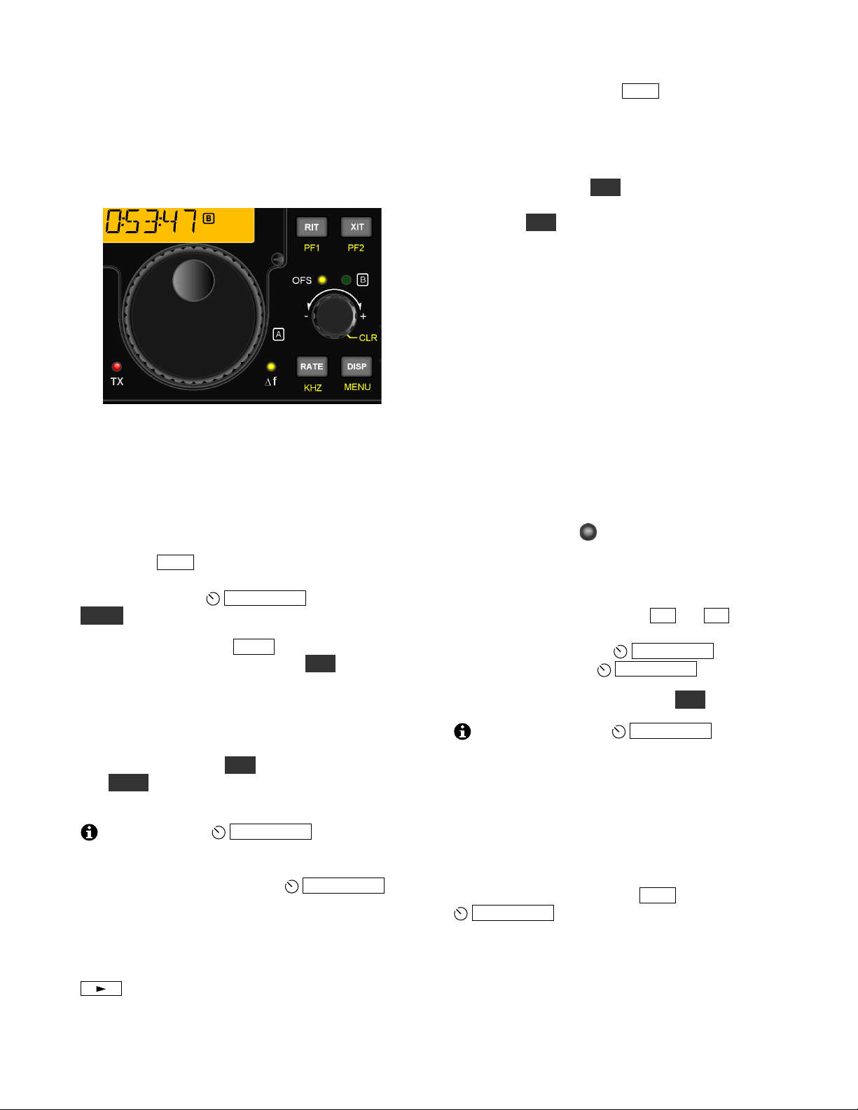
VFOs A and B
The KX3 provides two VFOs (see glossary, pg. 52).
Use of VFO B is optional. The VFO knobs are
located in the area shown below. Each VFO has
independent frequency, mode, and filter settings.
VFO A normally controls both the receive and
transmit frequency. Most contacts occur between
stations tuned to about the same frequency, so if
you use VFO A to tune in a signal clearly, there’s a
good chance they’ll hear you when you transmit.
VFO B can serve as a holding register for a second
frequency of interest, then swapped with VFO A as
needed (see A / B at right). To tune VFO B
directly, first make sure the B LED above the knob
is lit. If not, tap the
OFS/VFO B knob. Also see
SPLIT (pg. 19) and Dual Watch (pg. 20).
Tuning rates: Tapping RATE selects either 1 Hz
or 10 Hz VFO tuning rate. Holding KHZ selects a
per-mode coarse tuning rate (see MENU:VFO
CRS, pg. 30). SSB stations often align on 0.5 or 1.0
kHz boundaries. AM broadcast stations are
typically spaced at 5, 9, or 10 kHz.
To lock VFO A: Hold KHZ for about 3 seconds.
Tap RATE to unlock. To lock VFO B, swap it with
VFO A first, lock it, then swap back.
You can use the
OFS/VFO B control to
tune VFO A in coarse steps, while the VFO A
control itself is still set up for fine steps. First, make
sure the OFS LED is lit (tap the
OFS/VFO B
knob one or two times). RIT and XIT (described at
right) must also be turned off. To disable the VFO
offset-tuning feature, see MENU:VFO OFS.
To copy VFO A’s frequency to VFO B: Tap
A B . Tapping a second time copies VFO A’s
mode and filter settings to VFO B as well.
VFO A and B swap: Tap A / B to exchange VFO
frequencies, modes, and all other settings.
VFO A/B temporary reverse: Sometimes you’ll
want to swap the VFOs temporarily to look for an
open transmit frequency when operating split (pg.
19). In this case, hold REV. The VFOs will be
swapped back as soon as you release the switch. In
FM mode, REV swaps receive/transmit frequencies
and the repeater offset direction (pg.15).
Incremental Tuning (RIT and XIT)
RIT, or receive incremental tuning, provides a
means of adjusting the receive frequency without
affecting your transmit frequency. This control is
sometimes called a clarifier since it can be used to
tune in SSB voice signals. But RIT can also be used
in CW and DATA modes, in the event that a station
calls you slightly off-frequency. RIT and XIT use
the tuning rate (1/10 Hz) selected for the VFOs.
XIT, or transmit incremental tuning, adjusts the
transmit frequency without affecting the receive
frequency. See Split and XIT, pg. 19.
∆ F (Delta-F) LED : Whenever an RIT or XIT
offset is in effect, or during split operation, the ∆ F
LED turns on as a reminder that your receive and
transmit frequencies are different.
To use RIT or XIT: First, tap RIT or XIT . This
turns on the RIT or XIT icon on the display, as well
as the OFS LED (above
OFS/VFO B ). Then
adjust the offset using
OFS/VFO B .
To zero the RIT/XIT offset: Hold CLR.
You can still use the
OFS/VFO B control
to tune VFO B, even if RIT or XIT is turned on.
Just tap the knob to switch its function back to VFO
B (the B LED will turn on). The RIT/XIT icons on
the LCD will retain their current states.
Special VFO B Displays
The VFO B display area can show several useful
parameters. To see these, tap DISP , then rotate the
OFS/VFO B control. This will cycle through
several displays including time, supply voltage,
current drain, power amplifier temperature,
synthesizer temperature, audio voltmeter, and
relative audio (dBV) meter. For details see pg. 22.
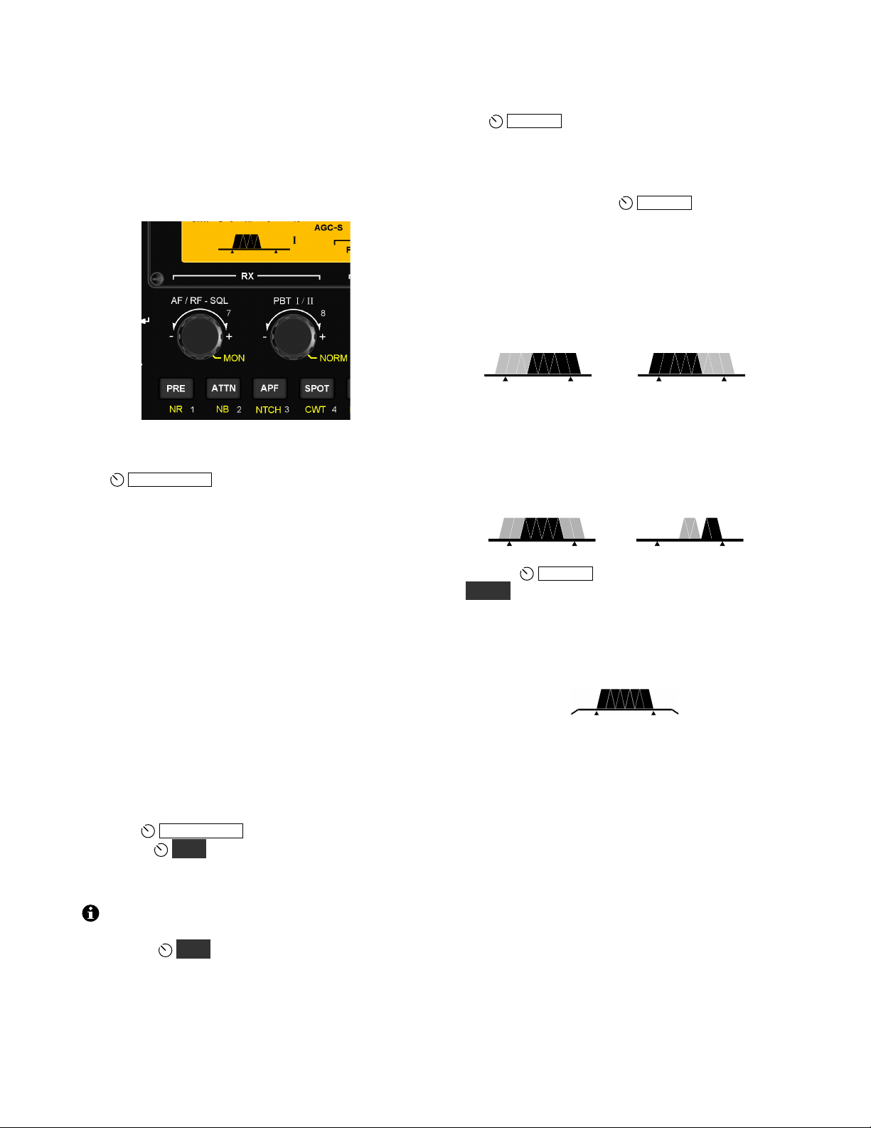
12
Receive Settings
The RX control group, shown below, is used to set
up the KX3’s receiver. Directly above these
controls is the filter passband graphic, which shows
the shape and position of the receiver’s passband.
This determines what pitch range you’ll hear.
AF Gain, RF Gain, and Squelch
The
AF / RF- SQL knob normally controls
receiver AF gain. Tapping the knob switches its
function to squelch (FM mode only) or RF gain
(all other modes). Also see “AF, RF, and IF” in the
glossary (pg. 52).
RF gain is normally left at maximum (- 0 dB).
Reducing RF gain may be useful in some strongsignal conditions. If you reduce RF gain more than
a few dB, a separate segment of the S-meter turns
on as a reminder. The segment used varies with the
amount of RF gain reduction. (A high S-meter
reading may hide the RF gain indicator segment.)
Squelch is used to mute the receiver until a signal
appears. It is most often used with repeaters. The
control adjusts the signal threshold required for
squelch to “open,” unmuting the receiver.
Voice Monitor/CW Sidetone Level (MON)
Holding
AF / RF- SQL temporarily switches its
function to
MON , which controls how much of
your own signal you hear when transmitting.
Transmit monitor setup is covered on pg. 14.
Switch activation tones, if used, have the same
volume level as the CW sidetone (as set in CW
mode using
MON ). Switch tones can be set to
off, on, or Morse code characters at various speeds
using the SW TONE menu entry.
Passband Tuning Functions (PBT I/II)
The
PBT I/II control is used to shape the KX3’s
receive filter passband. In general, a narrow
passband reduces interference (QRM) and noise
(QRN), while a wider passband improves fidelity.
In voice modes, tapping
PBT I/II normally
selects low-cut (function I) or high-cut (function
II). These functions remove low- or high-pitched
interfering signals. Examples of filter graphic
segments that might turn off as the result of a lowcut or high-cut are shown in light gray below. (To
select width/shift for SSB, instead, use PBT SSB.)
Low-Cut High-Cut
I
II
In CW and DATA modes, the passband functions
are width (I) and shift (II). The effect of these
functions is illustrated below. Reducing the width
or shifting the passband may attenuate an
interfering signal above or below the desired one.
Width Shift
I
II
Holding
PBT I/II normalizes the passband
(NORM), centering it and setting it to the default
width for the current mode. Two small "anchors"
appear at the left and right ends of the graphic.
Holding NORM again restores the previous
passband settings.
Roofing Filters (XFIL)
The XFIL icons, to the right of the filter passband
graphic, show whether the optional roofing filters
(FL2, FL3) are in use. These filters, located on the
KXFL3 option module, can reject strong nearby
signals that might interfere with weaker ones.
When FL1 is indicated, the roofing filters are
bypassed, and the pre-DSP bandwidth is about 15
kHz. FL2 (3000 Hz) and FL3 (1000 Hz) are
automatically selected, when possible, based on the
operating mode and settings of the filter controls.
Dual watch (MENU:DUAL RX) also uses FL1,
overriding the normal per-mode filter selection.
13
Preamp and Attenuator
PRE turns on the RF preamp. It should be used
only when signals are very weak. Preamp gain can
be set on a per-band basis using MENU:PREAMP.
ATTN turns on the 15-dB RF attenuator, which can
protect the receiver from strong interfering signals.
The KX3 will automatically reduce receive gain
in the presence of very strong signals. The receive
overload icon (RX) will alert you to this (pg. 8).
Noise Reduction
Noise reduction (NR) removes random background
noise (hiss or static). It has a characteristic “hollow”
sound. Higher settings may attenuate weak signals.
Holding NR turns on noise reduction and displays
its setting, which can be adjusted using the knob
above the switch. Tap any switch to exit the setting
display. Hold NR again to turn noise reduction off.
Noise Blanking
Noise blanking can eliminate repetitive noise such
as that from power lines, appliances, and vehicle
ignitions systems. Use the lowest effective setting
to avoid unwanted signal/noise interaction.
NB turns on the noise blanker. The NB setting is
adjusted in the same way as NR (see above).
Audio Peaking Filter (APF)
APF turns on a very narrow filter that improves
copy of very weak CW signals buried in noise. The
filter graphic changes to that shown below. With
APF on, PBT function I still adjusts the overall
passband width; function II tunes the APF center
pitch. 1-Hz VFO tuning is automatically selected.
Notch Filtering
In CW and data modes, holding NTCH turns on a
manually adjusted notch filter and displays the
notch pitch. Adjust the pitch, using the knob above
the switch, until an interfering carrier is reduced in
volume. Tap any switch to exit the notch pitch
display. Hold NTCH again to turn it off.
In SSB and AM modes, NTCH turns on auto-notch,
which locates and suppresses one or more carriers
automatically.
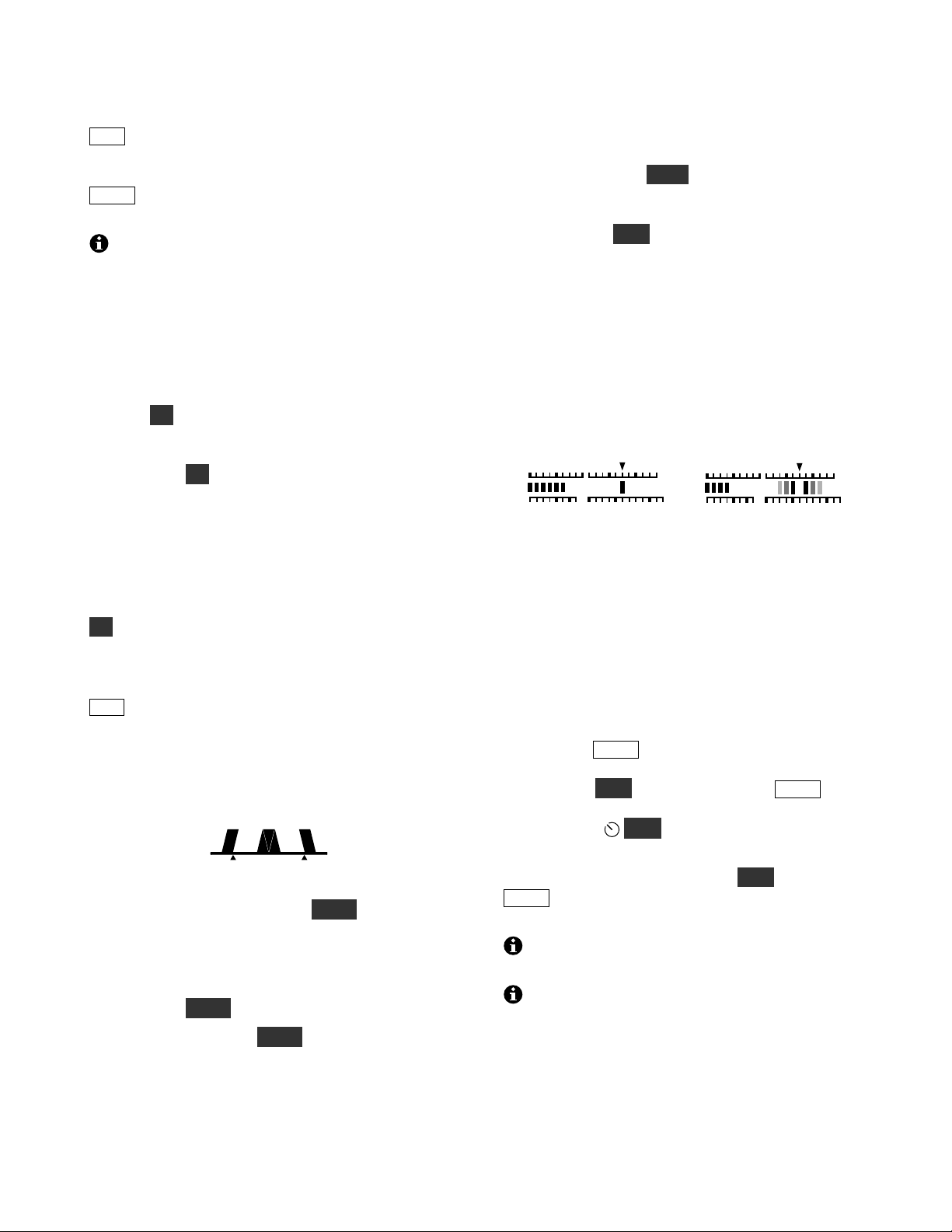
CW/DATA Tuning Aid (CWT)
Accurate tuning of received signals is required
before you call a station, or when you’re using
built-in text decode (TEXT, pg. 16). Tuning can be
done by ear. But CWT, in conjunction with Auto-
SPOT (below), can often tune in stations for you.
When you hold CWT , the upper half of the S-meter
becomes a receive VFO tuning aid for CW and
some data modes.
A CW signal will appear as a single bar in the CWT
display, as shown in the left example below. Use
VFO A to tune in the signal until the bar directly
under the CWT pointer is turned on. A narrow filter
width is recommended (100-400 Hz). This display
also applies to PSK31 (PSK D, pg. 18).
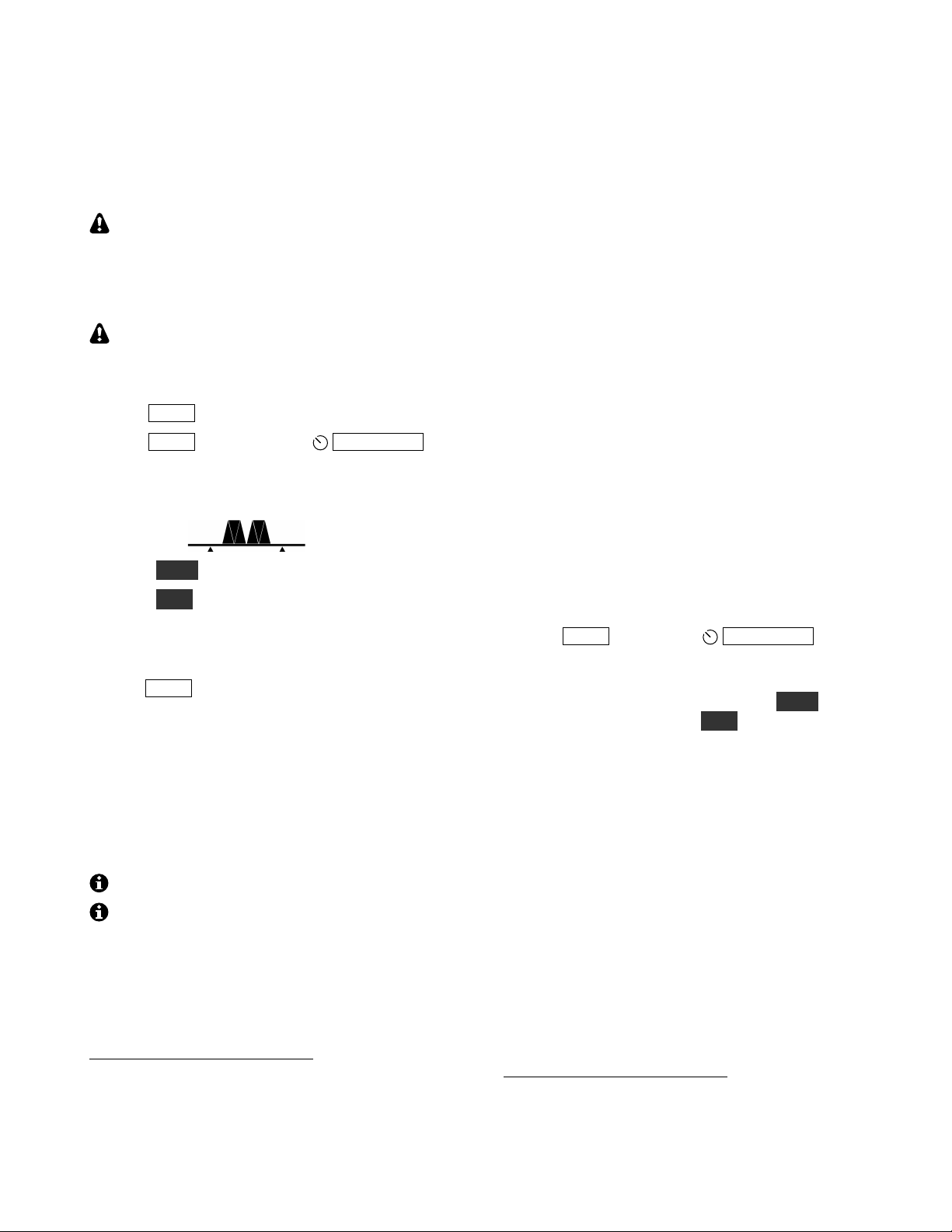
CW and PSK31 RTTY
In RTTY or radioteletype modes (FSK D, AFSK A;
pg. 18) mark and space tones are represented by
three bars on either side of the CWT pointer. If no
RTTY signal is present, you’ll see the “ghosting”
effect shown above. As you tune in an RTTY
signal, the number of solid bars will increase. Keep
tuning until you see a rough balance between left
and right solid bars during an RTTY transmission.
SPOT and Auto-SPOT
You can use SPOT to manually tune in a CW or
PSK31 signal, matching it to your sidetone pitch.
First turn off CWT if it is on. Then, tap SPOT and
adjust VFO A until the signal pitch matches the
sidetone. Use
MON to adjust the sidetone
volume level.
To use auto-SPOT: First turn on CWT . Tapping
SPOT will then automatically tune in a received
signal that falls within the CWT display range.
If RIT is turned on, auto-SPOT will change
the RIT offset, not the VFO A frequency.
Auto-SPOT may not be usable if more than one
signal is in the CWT range, or if the signal is very
weak or noisy. Try using a narrower bandwidth in
this case.
50
100
23SWR
RF
CWT
S135
7
9
50
100
23SWR
RF
CWT
S135
7
9
14
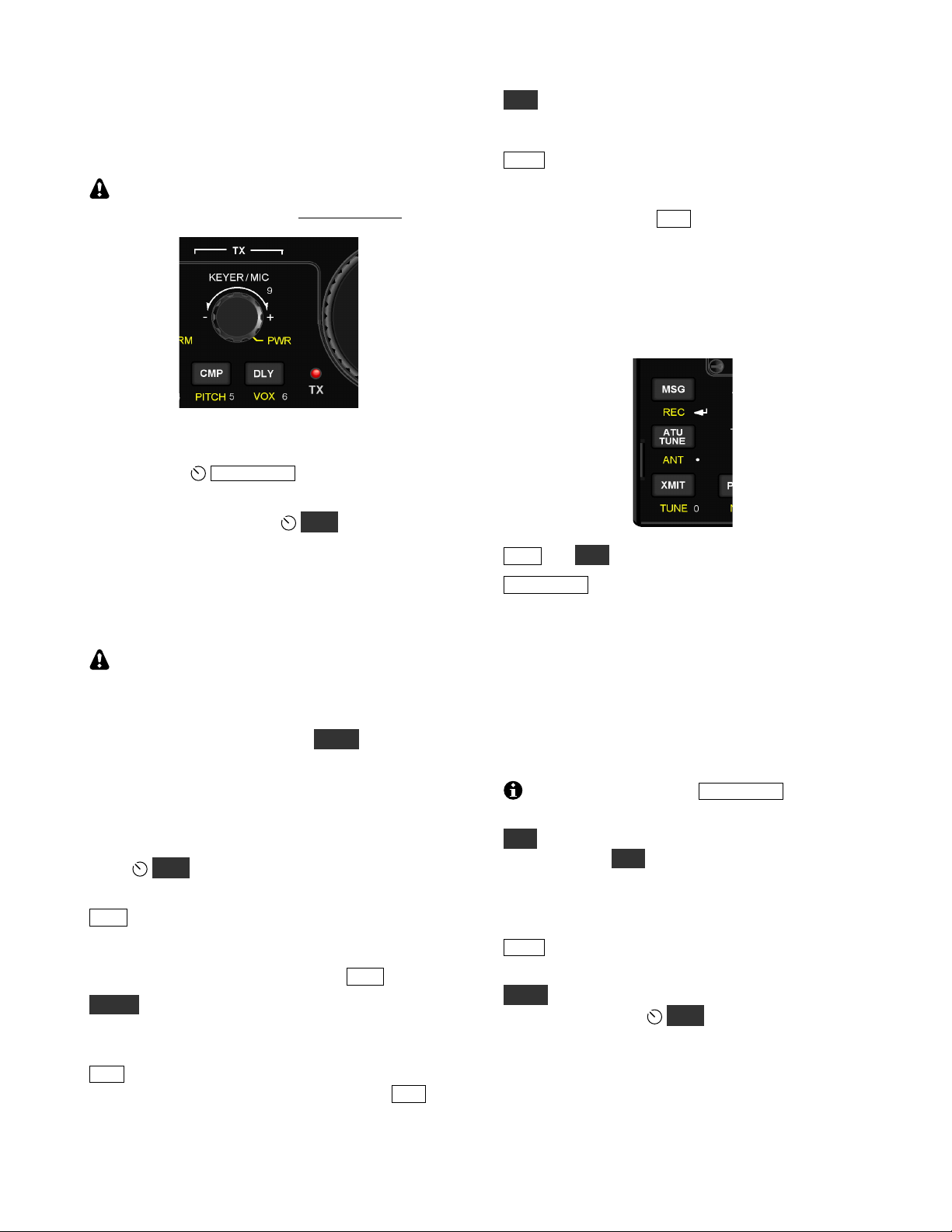
Transmit Settings
The TX control group is used to set up the KX3’s
transmitter. The TX LED turns on during transmit.
Caution: Also follow the detailed TX setup
instructions in later sections for each mode.
Keyer Speed/Mic Gain and Power Output
In CW mode,
KEYER/MIC sets the keyer speed
(in WPM). In voice modes, it sets mic gain.
A hold of this knob selects
PWR (power out).
Power in watts is shown on the RF bar graph.
Power output is typically 10 W+ on 160-15 m, and
8 W+ on 12-6 m. The 6-m setting is independent.
If a KXPA100 amp is connected, power can be set
up to 110 W (see KXPA100 owner’s manual).
Maximum available power output varies. If
power is lower than expected, use the special VFO
B displays (pg. 11) to check supply voltage, current
drain, and PA temperature. The selected parameter
will be shown on VFO B during TUNE (SWR is
shown on VFO A). A reduced-current TX mode is
automatically used when possible. This is indicated
by a decimal point after the “W” (e.g. 3.0 W.).
Other Transmit Settings
Hold
MON to set the transmit monitor volume
(speech in voice modes, sidetone in CW mode).
CMP sets the amount of speech compression,
which increases average power output, making your
voice sound louder. Adjust compression using the
knob above the switch; to finish, tap CMP again.
PITCH sets the sidetone pitch in CW mode, and
the tone-encode pitch in FM mode (pg. 15). Mark
or center pitch is shown in some data modes.
DLY sets the VOX (voice-operated transmit) delay
time in voice modes (pg. 15). In CW mode, DLY
sets the break-in or QSK delay (pg. 16).
VOX selects the keying mode: PTT (push-to-talk)
or VOX (voice- or keying-operated transmit). With
PTT selected, the transmitter is enabled by tapping
XMIT or by holding the mic’s PTT button. With
VOX selected, the VOX icon turns on, and transmit
starts by speaking (voice modes) or when keyed
(CW mode). Also see DLY (at left) and
MENU:VOX GN (p. 35).
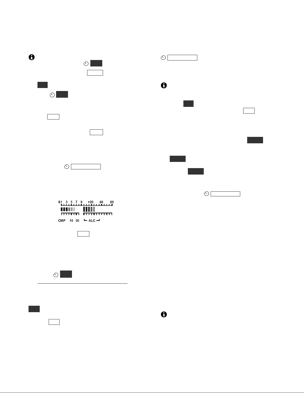
Transmit and ATU Control
The switches in the group shown below perform
various transmit control functions.
MSG and REC play/record messages (pg. 16, 21).
ATU TUNE starts automatic antenna matching if a
KXAT3 internal ATU is installed (pg. 25). The
ATU MD menu entry must be set to AUTO mode.
Matching takes an average of 4 seconds, initially.
Settings are then recalled instantly on band change,
as well as when you transmit after moving the VFO
a significant distance. The ATU icon will flash
briefly whenever new L-C network settings are
recalled. In CW mode, recall of settings is delayed
until a brief pause in keying (about 0.5 seconds).
With difficult loads, tap ATU TUNE a second
time within 5 seconds to search for a lower SWR.
ANT controls ANT1/2 selection on the KXAT100
external ATU. ANT does not switch between
antenna jacks on the KX3 itself. The BNC jack is
always used on the 160-6 m bands, and the SMA
jack is used only with the KX3-2M/4M module.
XMIT is equivalent to PTT (push-to-talk). Tapping
this switch places the KX3 into transmit mode.
TUNE is used to put out a CW signal at the power
level selected by the
PWR control. This is useful
with external wattmeters and antenna tuners. If the
TUN PWR menu entry is set to a numeric value,
rather than NOR, then this value—if lower—
overrides the power control setting.
15
Voice Modes (SSB, AM, FM)
Basic Voice-Mode Setup
To avoid transmitting a signal during voice-
mode setup, you can set PWR to 0.0 watts.
! Choose a mode: Tap MODE to select
LSB/USB, AM, or FM mode. In SSB modes,
ALT alternates between LSB and USB.
! Hold
MON to set the voice monitor level.
High MON settings may result in audio
clipping or distortion. Start with 3 to 5.
! Tap CMP and set it to 0 using the knob above.
Tap it again to exit the CMP display.
! Enable transmit: Tap XMIT or hold in the
mic’s PTT switch. Note: Hand mics like the
Elecraft MH3 should nearly touch your mouth
when you are speaking (about 1/8” [3 mm]).
! Adjust mic gain level: While speaking into the
mic, adjust KEYER/MIC (mic gain). This
will turn on the transmit CMP and ALC bar
graphs. While speaking, adjust mic gain for
about 5 ALC bars (see below). Mic gain for
the Elecraft MH3 is typically 15-25.
! Speech compression (optional): To use speech
compression, tap CMP and adjust the level
using the knob above the switch. While you’re
speaking, the CMP scale (see above), shows
compression level. High CMP settings may
result in distortion. Start with 1 to 10.
! Set the power level: Exit transmit mode and
adjust PWR to the desired output level.
Do not use MIC gain to set power level. Set
mic gain to a fixed level as described above.
Voice Mode VOX Setup
VOX selects push-to-talk (PTT) or voice-operated
(VOX) transmit (VOX icon on). VOX hold time is
set with DLY (pg. 14).
MENU:VOX GN (VOX gain) should be set to
trigger at normal speech level, but not in response
to incidental noise. Start with low settings (10-20).
MENU:VOX INH (VOX inhibit, or anti-vox) can
prevent speaker audio from triggering VOX.
Transmit Metering in Voice Modes
In voice modes, you can switch the transmit bar
graph from SWR / RF to CMP / ALC by tapping
KEYER/MIC. This also occurs automatically if
you adjust mic gain or speech compression level.
FM Operation
To disable FM mode, use MENU:FM MODE.
To setup for repeater use:
! Hold ALT to select simplex, TX up (+ ), or TX
down (-). If an offset is in effect, REV swaps
RX/TX frequencies and offset direction.
! Set up the repeater offset (MENU:RPT OFS).
! Select FM VFO step size (MENU:VFO CRS).
! If PL tone encode is required, hold PITCH to
turn it on (T icon), and rotate the knob above
this switch to select the tone frequency. Hold
PITCH again to turn PL tone encode off.
Selecting 1750 Hz adds EU 0.5-s tone burst;
holding PITCH during TX extends the tone.
! To change the FM deviation level for voice and
PL tones, see MENU:FM DEV.
! Squelch: Tap AF / RF-SQL, then rotate the
knob to select the desired squelch threshold. (In
other modes, the alternate knob function is RF
gain.) Tap the knob again to return to AF gain.
DTMF (dual-tone, multi-frequency): To send
DTMF tones to activate repeater functions: (1) hold
PTT; (2) tap FREQ ENT to enable/disable DTMF
entry; (3) tap 0-9 (use numeric keypad) or special
characters (use MSG = #, ATU TUNE = *, MODE
= A, A/B = B, DATA = C, A>B = D); (4) release
PTT. Note: If transmit is started via the XMIT
switch rather than PTT, and FREQ ENT is then
tapped to enter DTMF tones, tap FREQ ENT again
before exiting transmit via the XMIT switch.
Otherwise XMIT will still be assigned to keypad
digit ‘0’, so it can’t be used to end transmit.
AM Operation
To disable AM mode, use MENU:AM MODE.
AM receive on the KX3 uses envelope detection.
You can also listen to AM signals in SSB modes.
In AM transmit, the RF bar graph will indicate
about 1/3 to 1/2 the power set by the power control.
Transmit efficiency is lower in AM mode than SSB
as discussed on pg. 10.

16
CW Mode
Basic CW-Mode Setup
! Mode selection: Tap MODE to select CW
(CW normal). In some cases an interfering
received signal can be eliminated by switching
to CW REV (CW reverse) using ALT. This
doesn’t affect transmit.
! Transmitter keying method: The VOX
switch selects either VOX or PTT keying for
CW mode. Most operators use VOX, allowing
the transmitter to be keyed immediately
whenever a hand key or keyer paddle is used.
To manually enable transmit via the XMIT
switch, select PTT.
! Set sidetone pitch using PITCH. The ideal
pitch for most operators falls in the range of
400-600 Hz. The receiver’s passband will be
centered at the pitch you select.
! Set sidetone volume using MON.
! Adjust the break-in delay: Tap DLY to set
the break-in or QSK delay (the time before the
receiver recovers after key-up). A setting of 0
provides “full break-in” or “full QSK.” (The
QSK icon will appear.) This allows the receiver
to recover quickly so you can hear another
station transmitting between your characters.
CW Receive Filtering
As conditions change, you may need to adjust the
filter passband as described on pg. 12. Also, you’ll
find the audio peaking filter (APF) to be very useful
with weak CW signals.
Off-Air Code Practice
Sending CW normally produces both a sidetone and
a transmitted signal. If PTT-CW is selected (by
holding VOX), hitting the key will generate only a
sidetone (unless you tap XMIT). This is useful for
code practice or keyer speed adjustment.
CW-Mode Menu Settings
Use the menu to set up iambic keying (CW IAMB),
keying weight (CW WGHT), and paddle
normal/reverse or hand key (CW KEY1 for the
KEY jack, and CW KEY2 for the KXPD3). Also
use CW WGHT for CW transmit in SSB mode.
CWT, SPOT and Auto-Spot
When calling a station, you should try to match
your frequency to theirs. To facilitate this, the KX3
provides both manual and automatic spotting for
CW, FSK-D, and PSK-D signals. See pg. 13.
CW Text Decode/Display
The KX3 can decode transmitted and received CW
signals, displaying the text on VFO B (pg. 19). This
is especially useful when you’re learning CW, or if
someone who doesn’t know CW is looking over
your shoulder while you make CW QSOs. It’s also
indispensable for CW-to-DATA operation (pg.18).
CW/DATA Message Record/Play
There are 6 text message buffers, each holding up to
250 characters. These apply to CW and to DATA
modes FSK D and PSK D.
Messages can be recorded using the KX3’s
built-in keyer function (using either your keyer
paddle or the KXPD3). An external keyer cannot be
used. Messages can also be created or edited using
the KX3 Utility computer application.
Message Record: To start recording, hold REC ,
then select a message buffer by tapping any of
switches 1 through 6 on the numeric keypad. The
remaining buffer space will be displayed as you
send. Tap MSG to terminate record.
Message Play: To play, tap MSG , then select a
message buffer (1 through 6 ). To cancel, tap XMIT
or hit the keyer paddle or hand key.
Message Erase: Hold REC , then select a message
buffer (1 through 6 ), then hold CLR.
Auto-Repeat: To auto-repeat a message, tap MSG ,
but then hold rather than tap a message switch (1
through 6 ). MENU:MSG RPT sets the message
repeat interval (1 to 255 seconds).
Chaining: Tapping a message switch during
playback chains another message onto the message
being played. Holding a message switch during
playback chains a repeating message.
17
Advanced Operating Features
Frequency Memories
The KX3 has 100 general-purpose frequency
memories (00-99), plus four quick memories
on each band, accessed by tapping 1 - 4 on the
numeric keypad. Each memory stores VFO A and B
frequencies, modes, and other settings.
Quick memories provide an easy way to get to
segments used for each operating mode. For
example, you could use quick-memory 1 as an SSB
starting point, use 2 for CW, 3 for data, etc., on
each band.
To store a general-purpose memory (00-99):
First hold STORE , then locate the desired memory
by rotating the VFO A knob. The VFO A
frequencies presently stored in each memory will be
shown as you scroll through them. When you reach
the desired memory number, hold STORE again to
finish, or tap any other switch to cancel.
To recall a general-purpose memory: Hold
RCL (recall), then select memory 00-99 using
VFO A. Tap any switch to exit.
To store a per-band quick memory: Hold
STORE, then tap the target quick memory (1 - 4 ).
To recall a per-band quick memory: Hold
RCL, then tap the target quick memory (1 - 4 ).
To erase a general-purpose memory: While
scrolling through memories to save or recall, hold
CLR. (Not applicable to quick memories.)
To add a text label to a general-purpose
memory: First hold RCL , then select a memory
(00-99) using VFO A. Next, rotate VFO B to
select each text label position in turn as indicated by
the flashing cursor. Use VFO A to change label
characters (A-Z, 0-9, and various symbols). After
editing, hold STORE to finish the operation.
Adding an asterisk (*) at the start of a label
designates a memory that is part of a channelhopping group (described at right).
The K3 Memory program (pg. 28) can be used
to simplify setup and labeling of memories.
Scanning
Scanning allows the KX3 to tune any portion of a
band continuously. Normal scanning mutes the
receiver until a modulated signal is found. “Live”
scanning keeps the receiver unmuted, and is
stopped by the operator. This is useful on very quiet
bands.
To use scanning:
! Set VFO A and VFO B to the desired start/end
frequencies. Also select an operating mode.
! Select a tuning rate for the scan using RATE
(10 Hz or 100 Hz), or KHZ (for fast scanning).
! Store this setup in any frequency memory.
! To start scanning:
! Recall a scanning memory using RCL.
! Hold SCAN to start scanning. To scan with the
receiver live (unmuted), continue to hold
SCAN until you see AF ON (about 2 seconds).
To stop scanning: Rotate VFO A or tap any
switch. To restart, hold SCAN.
Channel Hopping
Scanning (or manually tuning) among a group of
memories is referred to as channel hopping. This is
most useful on channelized bands (e.g., 60, 6, and 2
meters). The memories in the group must all be in
the same band, but can have different modes.
To set up channel hopping:
! Set up VFO A for the first target frequency and
mode. Store this setup in a general-purpose
memory (00-99) as described at left.
! Set up and store the remaining frequencies in
the next successive numbered memories.
! Add a text label to each memory in the group,
using an asterisk (*) as the first character.
To start manual channel hopping, RCL any one of
the memories in the target group. VFO A will now
hop among the grouped memories as you turn it.
You can then start scan (or live scan) among the
grouped memories using SCAN. To disable channel
hopping, tap RATE or change bands.
18
Data Modes
The KX3 supports data operation via a computer
and special software. But it can also be used in
RTTY and PSK31 modes without a computer via
the KX3’s built-in FSK D and PSK D modes.
5.0 watts or lower is recommended in all
data modes. The KX3 will reduce power, if
necessary, to maintain a safe operating temperature.
FSK D Mode (RTTY)
MIC gain, RX/TX EQ, and CMP are not
applicable to FSK D and PSK D modes.
FSK D (RTTY1) is the easiest data mode to use:
! Tap DATA to select data mode.
! Tap DATA again and rotate
OFS/VFO B to
select the FSK D sub-mode. Tap the switch
again to exit the sub-mode display. A dualpassband (mark/space) filter will appear:
! Hold TEXT to turn on text decode.
! Hold CWT to turn on the tuning aid (pg. 13).
You’ll now be able to copy RTTY signals. RTTY
can often be found on 20 meters from 14080-14090
kHz. (If you see only numbers and punctuation, try
tapping DATA twice to restore “letters” mode.)
To transmit in FSK D mode (CW-to-Data): Plug
a keyer paddle into the KEY jack, or attach a
KXPD3 paddle. (See the CW KEY1 and CW
KEY2 menu entries.) When you send CW, the KX3
will convert it to RTTY. (You’ll hear the CW
sidetone as well as weak RTTY tones.) You can use
CW message memories in FSK D mode, as well as
KX3 Utility’s Terminal function (pg. 28).
You cannot use a hand key for this function.
The KX3 adds a 4-second “idle time” (giving
you time to decide what to say next) after you stop
sending. To terminate the idle period quickly, send
the character
. .
- - in CW. This “IM” prosign can
also be inserted at the end of message buffers.
1
FSK stands for frequency-shift keying, used with RTTY
(radioteletype). The KX3 uses a 170 Hz shift. RTTY
signals are encoded using a 5-level code called baudot, at
a baud rate of 45 baud, or about 60 words per minute.
PSK D Mode (PSK31)
PSK D is the KX3’s built-in implementation of
PSK312, a narrow-band data mode which is reliable
even at very low power levels. 5 watts or less is
strongly recommended to keep distortion low.
To use PSK D, set up the KX3 as described at left
for FSK D, but select the PSK D sub-mode. Before
attempting to transmit in this mode, you should
practice tuning in signals. Try 14070-14073 kHz.
CWT can be used in this mode (see pg. 13).
DATA A and AFSK A (Audio Data Modes)
Many audio-generated data transmissions can be
heard on the bands, using PSK31, RTTY, Pactor,
Olivia, MFSK, JT65 and other modes. A computer,
sound card, and appropriate software are normally
used. DATA A mode is provided for this purpose.
Unlike SSB modes, DATA A disables compression
and RX/TX EQ. Upper sideband is the default.
For audio-based RTTY, you can also use AFSK A.
Like FSK D, AFSK A provides a dual-passband
RTTY filter and text decode. The VFO is tuned to
the mark frequency. Lower sideband is the default.
To use these audio data modes:
! Tap DATA twice; rotate
OFS/VFO B to
select the DATA A or AFSK A. Tap the
switch again to exit the sub-mode display.
! In AFSK A mode, optionally hold TEXT to
turn on text decode, and CWT to turn on the
CW/data tuning aid.
! Connect your computer’s audio output to the
MIC jack. (You can either wire the plug to
activate the PTT line on transmit, or use VOX.)
Connect the KX3’s PHONES jack to your
computer’s audio input. High-quality shielded
cables should be used. You may need an
attenuator if the drive levels are too high.
! Refer to your data communications software
manual to determine how to set up the KX3’s
VFO for accurate frequency display.
! While transmitting audio data, adjust MIC gain
for no more than 4 to 5 bars of ALC indication.
! RX/TX EQ and CMP are not applicable.
2
PSK stands for phase-shift keying. 31 refers to the baud
rate, 31.25 baud. PSK31 signals are encoded using a very
efficient representation called varicode.
 Loading...