

ELECRAFT KX2 Owner's Manual
ELECRAFT
Ò
KX2
POCKET-SIZED, 80-10 M SSB/CW/DATA TRANSCEIVER
OWNER’S MANUAL
Rev. A8, June 6, 2019 © 2019, Elecraft, Inc. All Rights Reserved

2
Contents
Introduction 4!
Key to Symbols and Text Styles 4!
Installation 5!
Operating Position 5!
Power Supply 5!
Internal Battery 6!
Utility Mounting Points (Bottom Cover) 7!
CW Key/Keyer Paddle 8!
Headphones and Speakers 8!
Internal Microphone 8!
External Microphone 8!
Computer/Amp Keying (ACC) 9!
Auxiliary Outputs (AUX) 9!
Program/Test (PGM) 9!
Antennas 10!
Control Panel Reference 12!
Display (LCD) 13!
Basic Operation 14!
Getting Started 14!
Band Selection 15!
Mode Selection 15!
VFO A and B 16!
Incremental Tuning (RIT and XIT) 16!
Special VFO B Displays 16!
Receive Settings 17!
Transmit Settings 19!
SSB Mode 20!
CW Mode 21!
AM Mode 22!
Advanced Operating Features 23!
Special VFO B Displays 23!
Frequency Memories 24!
Scanning 24!
Audio Effects 25!
Dual Watch 25!
Programmable Function Switch (PFn) 25!
Receive Audio Equalization (RX EQ) 26!
Transmit Audio Equalization (TX EQ) 26!
SSB/CW VFO Offset 26!
Data Modes 27!
Text Decode And Display 29!
Split Operation 30!
Digital Voice Recorder (DVR) 30!
Transmit Noise Gate 31!
Cross-Mode Operation 31!
Custom Power-On Banner 31!
Logging (CW/Data Modes) 32!
Transverter Bands 32!
Options and Accessories 33!
Firmware Upgrades 34!
Remote Control of the KX2 35!
Configuration 36!
Option Module Enables 36!
Menu Settings 36!
Calibration 38!
Reference Frequency 38!

3
Receive Opposite Sideband 39!
Transmit Bias 39!
Transmit Gain 39!
Transmit Carrier 40!
Transmit Opposite Sideband 40!
Menu Functions 41!
Troubleshooting 54!
Parameter Initialization (EEINIT) 58!
Error Messages (ERR nnn) 59!
Scrolling Alert Messages 62!
Theory Of Operation 63!
Glossary of Selected Terms 66!
Specifications 68!
Customer Service and Support 70!
Index 72!

4
Introduction
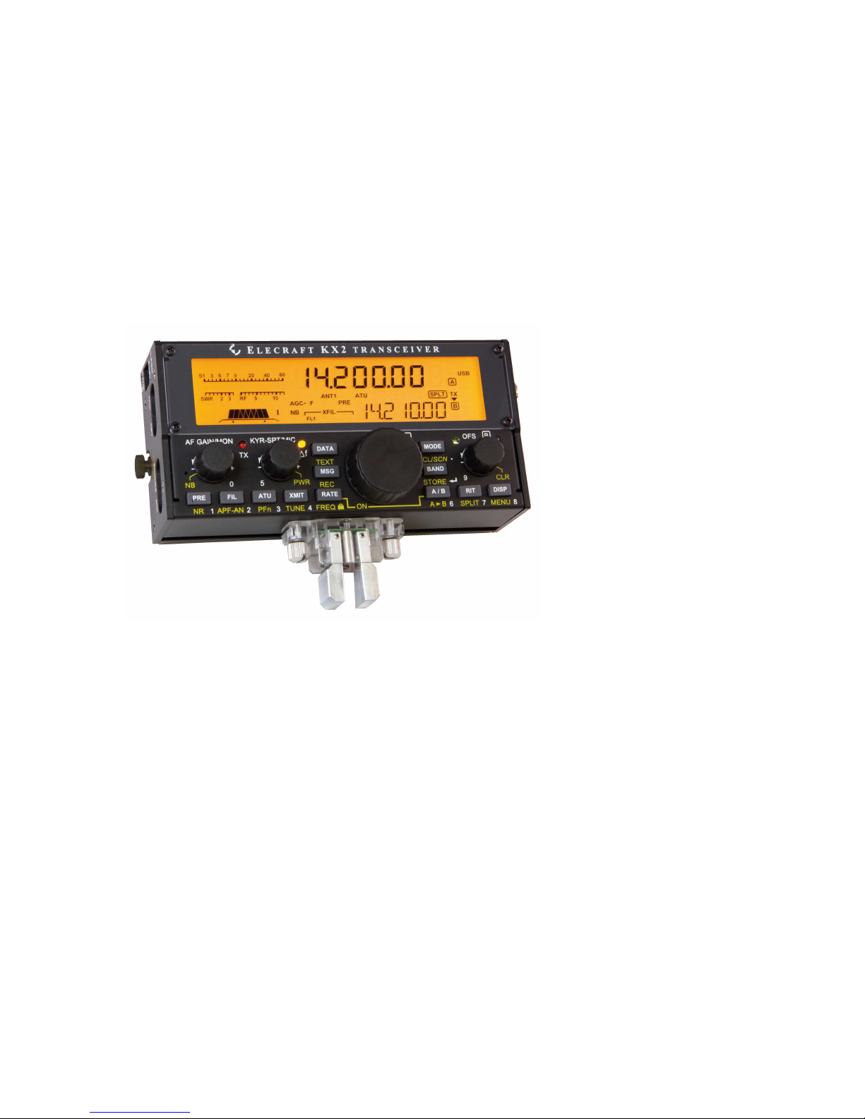
The Elecraft KX2 is a pocket-sized, 80-10 m, SSB/CW/data transceiver designed specifically for portable,
mobile, and hand-held operation. Weighing just 13 oz. (0.35 kg), it’s the perfect “grab and go” HF radio.
Despite its small size, the KX2 is a full-featured HF transciever, with up to 10 W output. Its powerful digital
signal processor (DSP) provides dual watch, built-in PSK and RTTY modes, digital voice recorder, stereo
audio, noise reduction, and various filtering functions. The KX2 can be configured as a complete station,
with internal antenna tuner (ATU), whip antenna (AX1), attached keyer paddle (KXPD2), and internal
battery (KXBT2). Current drain is about 150 mA, far lower than other DSP-based portable transceivers.
Since the KX2 is a software-defined-radio (SDR), you’ll be able to add new features via free firmware
upgrades. For mobile and home use, you can boost the KX2’s output to 100 watts with the optional
KXPA100 amplifier. The KXIO2 option adds a real-time clock, as well as two outputs that can be used for
antenna switching or other applications.
When your next adventure begins—whether at home or in the field—your KX2 will be ready.
73,
Wayne, N6KR
Eric, WA6HHQ
Key to Symbols and Text Styles
Important – read carefully
Operating tip
XMIT
TUNE
Tap function of a knob or switch
Hold function (hold switch 0.5 s)
LSB
.
Icon or text shown on the display
Enter keypad function
Locked (VFO or menu parameter)
MIC
BKLIGHT
Rotary control (knob) function
Menu entry
5
Installation
CAUTION
§ Be careful when plugging in cables. Avoid
sideways pressure that might damage the jacks.
§ Avoid direct exposure to rain or snow (the KX2
is not waterproof).
§ Avoid operating at very high temperatures.
§ Prior to opening the enclosure, touch a grounded,
unpainted metal surface to avoid static discharge.
Operating Position
As shown below, the tilt leg on the back of the KX2 can
be used to optimize the viewing angle. Loosen the rear
thumbscrew to adjust the tilt leg. The KX2 can also be
operated hand-held, either vertically or horizontally.
Power Supply
For fixed-station use, a low-noise 12-14 VDC power
supply or battery is recommended. For lightweight
portable operation, an internal battery can be used.
See next page for internal battery installation.
Batteries or power supplies can be plugged in from
inside, outside, or both. The internal and external DC
jacks are identical, and are diode-isolated from each
other. The higher voltage will power the transceiver.
Power output varies with supply voltage.
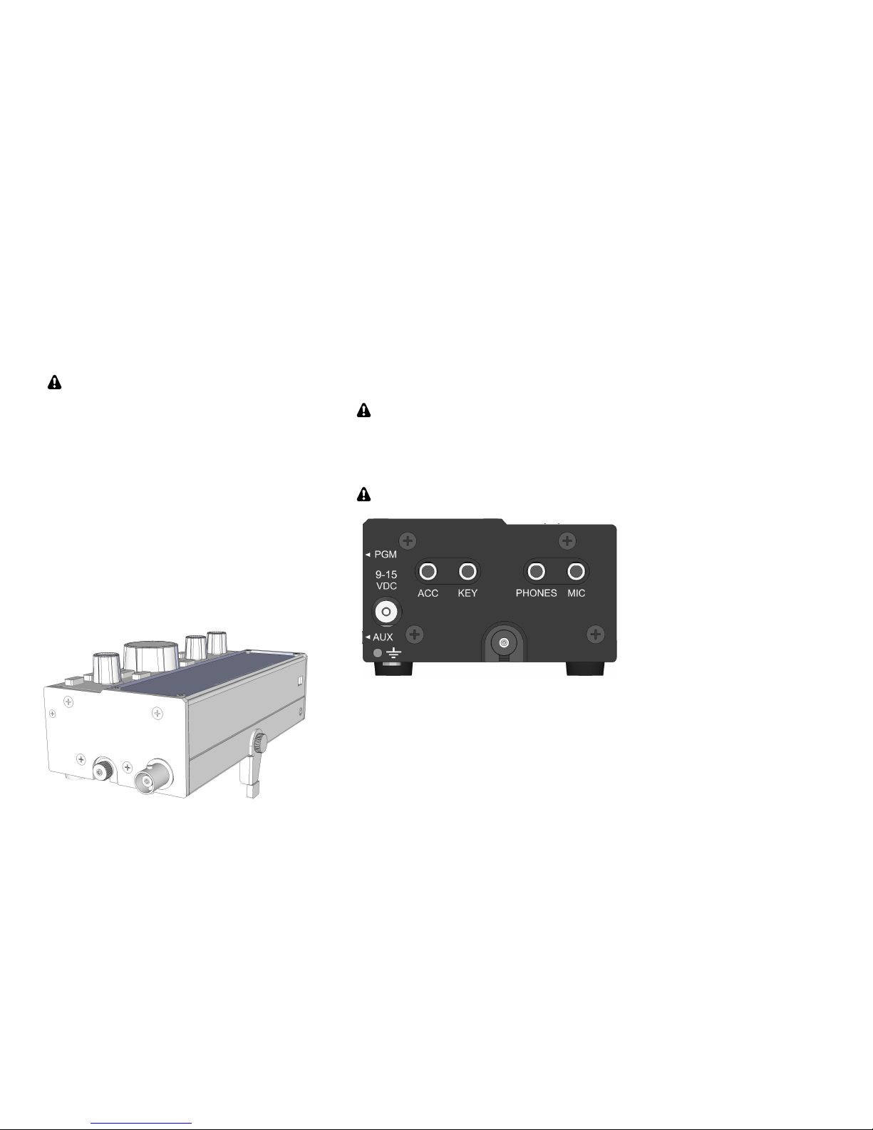
An external power supply or battery can be connected
to the 9-15 V jack on the left side panel (see above).
The center pin is (+). The plug can be a Switchcraft
model S760 or similar (2.1 mm aperture, 5.5 mm dia.).
The white striped wire on the supplied cable is (+).
Trim the cable to the desired length.
(+)
6
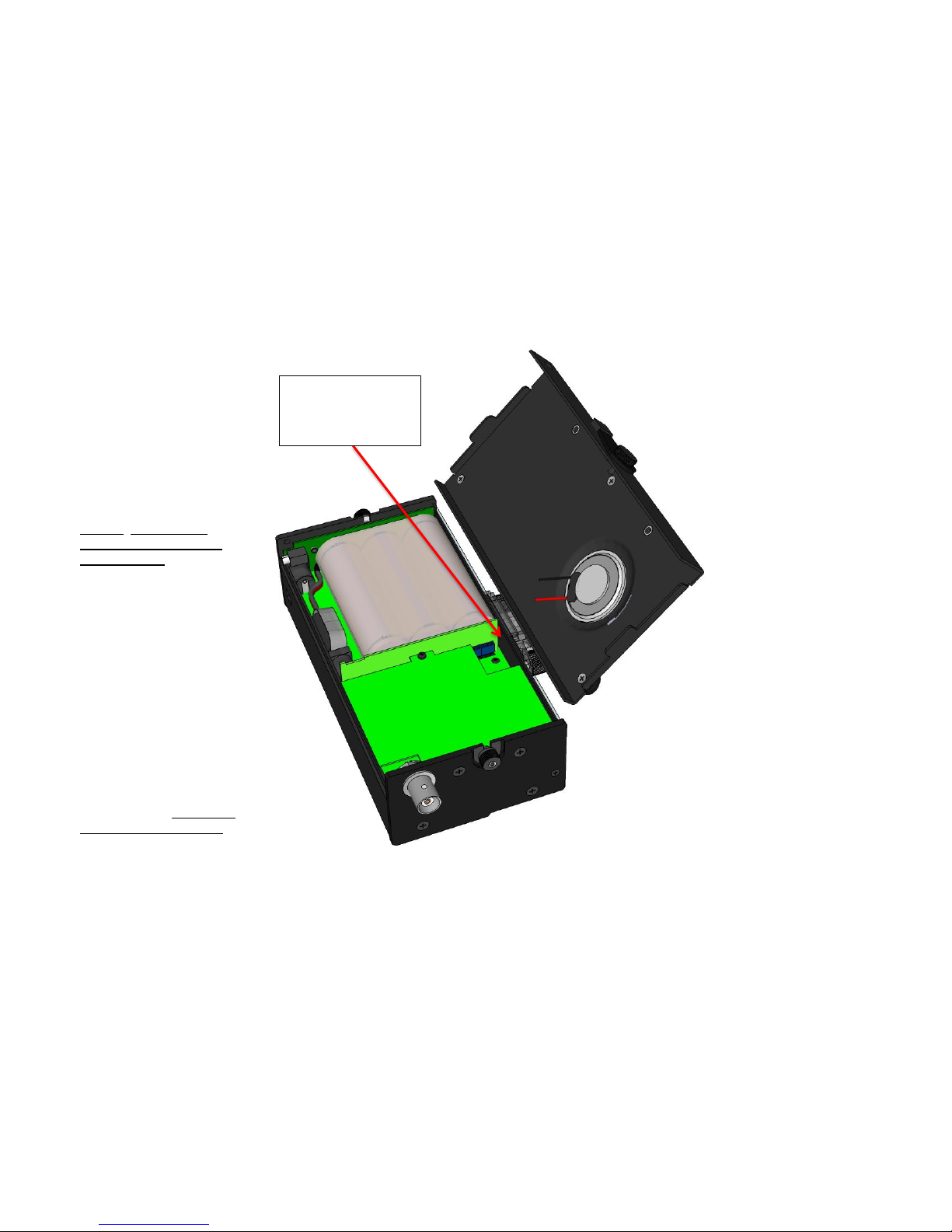
Internal Battery
The KXBT2, shown here installed,
is an 11 V, 2.6 Ah li-ion battery
with protective circuitry.
Battery installation:
• Loosen the two thumb nuts at
the ends of the bottom cover.
• Rotate the cover open,
keeping speaker wires
captivated in the location
shown at right.
• Place the battery as shown and
plug it into the internal jack.
• Make sure battery wires are
tucked inside, beside the plug.
• Install the bottom cover.
• Tighten the two thumb nuts
firmly to keep the bottom
cover in place.
Battery removal:
• Open the bottom cover as
described above.
• Pull the battery plug out
slowly, using the provided
nylon pull-loop. Do not pull
on the battery pack wires.
• Replace the bottom cover and
tighten the thumb nuts firmly.
Note: Speaker wires are
routed between the small
band-pass filter board
and the chassis.

7
Using the Battery Safely
Misusing a lithium-ion battery may cause it to
get hot, rupture, or ignite and cause serious injury;
or result in loss of performance and shortened life.
The KXBT2 battery pack weighs only 4.8 oz, and can
provide up to 8 hours of typical transceive operation
and up to 10 W power output. To ensure safe
operation, please take a moment to read the
information sheet supplied with the battery.
The pack is fitted with a 2.1 mm DC barrel plug. The
KX2 has two DC barrel jacks: one inside, and one on
the left side panel. These jacks are isolated from each
other, but either can power the KX2. You can plug in
an internal battery and an external supply, and the
radio will operate from whichever is higher in voltage.
Battery Charging
The battery must be charged using only the
matching KXBC2 smart-charger.
To charge the battery, you must first remove it as
described on the previous page. It cannot be charged
while inside the KX2. The power jack on the left side
panel is isolated from the internal power jack, and
cannot supply power to the battery.
Plug the battery into the jack on the charger, then plug
the charger into a 120 VAC outlet. The charger’s LED
will be red during charging, and GREEN when charge
is complete. A full charge cycle typically takes 1 to 2
hours depending on the state of charge.
Amp Hour Metering
The KX2 includes an amp hour meter function that
allows you to better estimate remaining battery life.
See pg. 16 for the associated special display function,
as well as the AMP HRS menu entry.
Preserving Clock Time During Charging
The KXIO2 option module includes a real-time clock
(RTC), useful for logging (see LOGGING menu
entry). RTC circuitry is powered by the battery or
power supply connected to the KX2 (internal or
external).
When no power supply or battery is connected, the
RTC’s time registers are preserved for up to 2 hours by
a supercapacitor on the KXIO2. In most cases this
allows sufficient time to remove the battery from the
KX2, charge it, and reinstall it without losing the time
setting.
Utility Mounting Points (Bottom Cover)
The KX2’s bottom cover has two threaded fasteners
(4-40 PEM nuts) for light-duty applications. For
example, they could be used to attach the transceiver to
a clipboard for field logging, or for storage of a
counterpoise wire (see pg. 10, right column).
CAUTION: These fasteners are not intended
for use with a mobile mount. Also, do not allow
screws or other hardware to protrude more than
0.1” into the interior of the KX2.
8
CW Key/Keyer Paddle
The KX2 has two CW keying inputs:
Attached Keyer Paddle: An Elecraft KXPD2 (or
KXPD3) keyer paddle can be attached at the front of
the KX2 via two thumb screws. Use the CW KEY2
menu entry to reverse the dot/dash sides.
KEY Jack: This jack can be used with any hand key,
keyer paddle, or other keying device, as configured by
the CW KEY1 menu entry.
A stereo plug is required at the KEY jack, even
if only the tip contact is being used.
Headphones and Speakers
The 3.5 mm PHONES jack accommodates
headphones or one or two externally amplified
speakers. Mono or stereo plugs can be used. Stereo
audio allows the use of dual watch and audio effects
(pg. 25).
Built-In Speaker: The speaker, located on the bottom
cover, sounds best when the tilt foot is used.
Headphones or external speakers will provide
greater bass response than the internal speaker.
Mobile installations: For mobile use, amplified
mobile speakers or an aux input on your car’s stereo
can be connected to the PHONES jack. Another
alternative is to use a device that retransmits the KX2’s
audio output in the FM broadcast band.
Internal Microphone
For emergency or hand-held use, the KX2 includes a
built-in mic, located to the left of the AF/MON control.
(There’s a small hole in the panel at this location.) The
built-in mic is automatically turned on when no
external mic is plugged in. Tap XMIT to transmit.
To prevent acoustic feedback, the transmit voice
monitor function (MON) is disabled when using the
internal mic with the internal speaker.
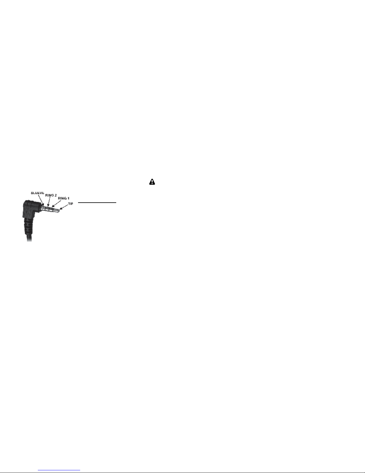
External Microphone
The 3.5 mm MIC jack is compatible with the Elecraft
MH3 hand mic, which provides PTT as well as VFO
UP/DN buttons. For the MH3, set the MIC BIAS menu
entry to ON, and MIC BTN to PTT UP.DN.
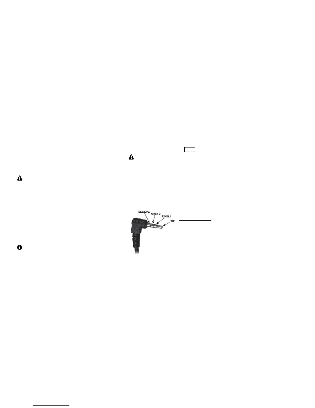
MIC Jack Pinout
Sleeve: Shield ground
Ring2: Logic ground
Ring1: PTT/UP/DN
Tip: Mic audio
The KX2 will work with many other mics, including
“mini” mics intended to plug directly into a computer.
Refer to the MIC BIAS and MIC BTN menu entries to
set up the KX2 for use with your mic or headset.
9
Computer/Amp Keying (ACC)
The 3.5 mm accessory jack (ACC) facilitates firmware
updates and remote control of the KX2 via a computer,
and/or connection to an Elecraft KXPA100 amp. In
either case, a standard stereo plug can be used (see
sleeve, ring 1, and tip connections below). The
supplied KXUSB cable can be used for this purpose.
ACC Jack Pinout
Sleeve: Ground
Ring 2: *Key Out
Ring 1: TX Data
Tip: RX Data
* For external ampflier keying, the ACC jack’s key out
signal (on Ring 2) may also be needed, as described at
right. In this case a 4-circuit (TRRS) plug is required.
Computer Applications
KX2 Utility is required for firmware configuration and
updates (pg. 34). The utility program also provides a
CW/data terminal function. Our Elecraft Frequency
Memory Editor can be used to set up frequency
memories.
Many logging, contesting, and control programs are
available from third parties. If the KX2 is not
specifically supported, try using Elecraft KX3 or K3.
Amplifier Keying
The ACC jack provides a key out signal (Ring 2
contact, shown at left). Key out goes low during
transmit, and can be used for transmit/receive
switching of linear amplifiers and transverters. For
keyline voltage and current limits, see Specifications.
If the key out signal is not required, a regular stereo
plug can used (3-circuit). This will short the key out
signal to the sleeve (ground), but will not cause any
damage or consume additional current.
An Elecraft KX2 Accessory Cable (KX2ACBL) can
be used to break out the computer control and key out
signals separately. These can then be connected to both
an Elecraft KXPA100 ampflier via its supplied cable.
Auxiliary Outputs (AUX)
If the KX2 is fitted with a KXIO2 (pg. 33), then a 2.5
mm AUX jack will be available. This jack provides
two general-purpose outputs that can be programmed
on a per-band basis to control equipment such as an
antenna switch or transverter. On the connector, the
sleeve is ground, tip is AUX 1, and ring is AUX 2.
Program/Test (PGM)
This jack is reserved for Elecraft factory test use.
10
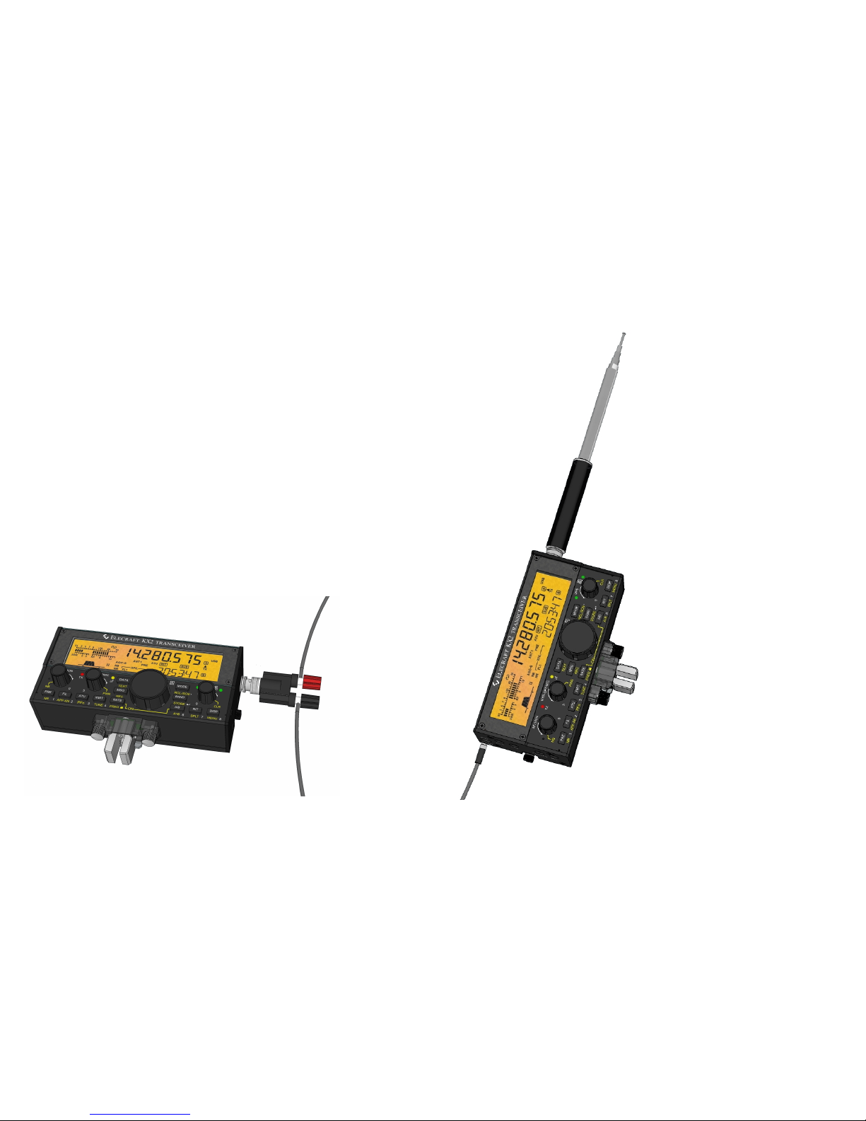
Antennas
General information on antennas can be found on the
next page. Here, we show two examples of antennas
for portable operation that can be set up quickly.
The illustration at left shows a simple wire antenna
connected to a KX2 via a BNC-to-binding post adapter
(Elecraft BNC-BP or equivelant). The wire tied to the
red post (antenna hot lead) is attached to a tree or other
tall support. The wire tied to the black post (radio
chassis ground) is the equally important counterpoise,
which is typically laid on the ground.
A length of about 25 feet for each wire, matched to the
KX2’s output using an antenna tuner (see ATU, pg. 11)
will typically provide good performance on 40-10 m.
(Without an ATU, resonant lengths are required for
each band.) This antenna is ideal for outings where all
gear must fit into a small bag (e.g, our model CS-40).
At right, a KX2 is shown in hand-held orientation
with a telescoping whip antenna. An Elecraft AX1
or similar lightweight whip is recommended.
(Such antennas are electrically short, making
contacts more challenging. Best results will
be obtained on 20 meters and higher.)
When using a whip antenna, you’ll also need a
counterpoise wire, shown here attached via
a mini-banana plug (Elecraft model
KX2GNDPLUG). A length of about
13 feet is a good compromise for 20-10
meters. This is sometimes called a
“trailing ground” by those who operate
pedestrian mobile (/PM). If you step
on the counterpoise wire, or get it
snagged, the mini-banana plug
will pull out safely, avoiding
damage to the KX2.
Wire to tree or
other support
Counterpoise
Wire
BNC-to-binding
post adapter
Counterpoise
Wire
Mini-banana plug

11
General Antenna Information
An antenna must be connected to the BNC jack via
either coax or an adapter. If an antenna tuner is not
used (either an external tuner or an internal KXAT2),
then a resonant antenna having a 50 ohm
(approximate) load impedance on each band of
operation is required. Examples can be found in the
ARRL Antenna Handbook and other sources. A coaxfed inverted “V” or dipole can be very effective.
SWR: One measure of how close an antenna is to
resonance is its SWR (standing wave ratio). The KX2
displays SWR when you use the TUNE switch (pg.
19). An SWR of 1:1 (1.0-1 on the KX2’s display) is
considered a “perfect” match. To ensure safe operation,
the KX2 reduces power output if SWR is too high.
Using An Automatic Antenna Tuner (ATU): An
ATU will allow the KX2 to “see” a good match in
many cases (i.e., a low SWR) even with non-resonant
antennas. This allows the transmitter to deliver full
power, and can improve receiver sensitivity. An ATU
may allow one antenna to be used on multiple bands.
You can use an external or internal ATU. The KXAT2
(ATU option, pg. 33), stores matching data for each
band; retuning takes less than 1 second. Data sets are
provided for home/field use (MENU:ATU DATA).
Antenna Wire: Insulated, stranded wire works well
for portable antennas. We recommend #26 “Silky”
from The Wireman (catalog #534). To avoid kinks,
wire can be wound in a figure-8 pattern. For tossing
wire into tree branches, attach a 1 to 2 oz. weight (such
as stainless-steel hex nut) to the end of the wire.
Feedline: When using low power, antennas can often
be directly connected to the KX2 without any coax or
other feedline. This is shown in both of the simple
portable antennas on the previous page. However,
balanced antennas such as dipoles and inverted Vs will
function better when their feed point is physically well
above ground.
Resonant antennas (those which are cut to length for a
given frequency) are typically fed with 50 ohm coax.
RG-174 is a good choice when light weight is required.
Random-length antennas can be fed with twin-lead,
then connected to a balun (balanced-to-unbalanced
converter), such as the Elecraft BL1 or BL2. The balun
can then be connected directly to the transceiver (if an
internal ATU is used) or to an external ATU.
Ground and Counterpoise Systems: A ground or
counterpoise is needed with many antennas. The ARRL
Antenna Book provides examples. This is definitely
needed when you use a whip, vertical, or random wire.
The ground or counterpoise can be connected to the
KX2 via the bottom cover thumb nuts or to the outer
shield of the BNC jack. There’s also a hole in the left
side panel, identified by a ground symbol, that is sized
for a mini-banana plug. This is ideal for a quickdisconnect trailing ground wire used during pedestrian
mobile operation. See example on previous page.
For improved performance, use at least one 1/4wavelength radial for each band when possible.
Adding more radials on a given band will further
reduce losses, especially when transmitting.
12
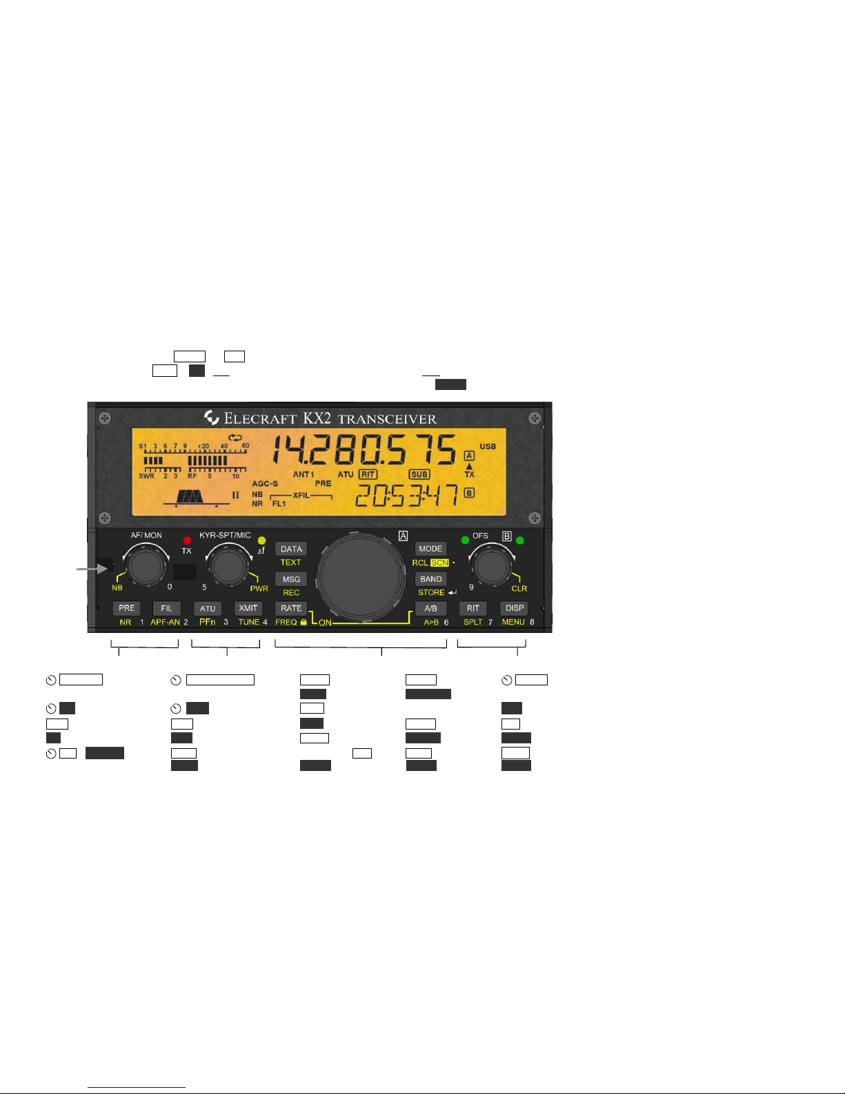
Control Panel Reference (For details, refer to page numbers shown in parentheses)
Power ON/OFF: Hold both the RATE and A/B switches for 2 seconds (see “ON” label below the VFO A knob).
Tap / Hold Functions, e.g. PRE / NR: Tap to use the function labeled on or above a control; hold ½-sec for the function labeled below it.
Numeric Keypad: Twelve of the switches and knobs form a keypad (0-9/decimal/enter) for use with FREQ, etc.
Receive Transmit VFO A / Band / Mode VFO B / Misc.
AF/MON AF gain (17); KYR- SPT /MIC DATA Data mode (27) MODE CW/SSB (15) OFS/B Coarse VFO
tone/monitor level (17) Keyer (19); Spot (21); Mic gain (19) TEXT Text decode (29) RCL/SCN F. recall tuning (16);VFO B (16)
NB Noise blanker (18) PWR Power level (19) MSG Msg play (19, 30) (24), Scanning (24) CLR Clear RIT (16)
PRE Preamp / attenuator (17) ATU ATU tune (19) REC Msg record (19, 30) BAND Band (15) RIT Receive offset (16)
NR Noise reduction (18) PFn Prog. switch functions (25) RATE VFO tuning (16); STORE F. store (24) SPLIT Split RX/TX (30)
FIL / APF- AN Filtering XMIT TX/PTT (19) ON/OFF (with A/B) A / B A/B swap (16) DISP Special disp. (23)
(17); APF (18); auto-notch (18) TUNE CW carrier (19) FREQ Freq. entry (15) A > B A>B copy (16) MENU Menu (14)
Internal
Mic
13
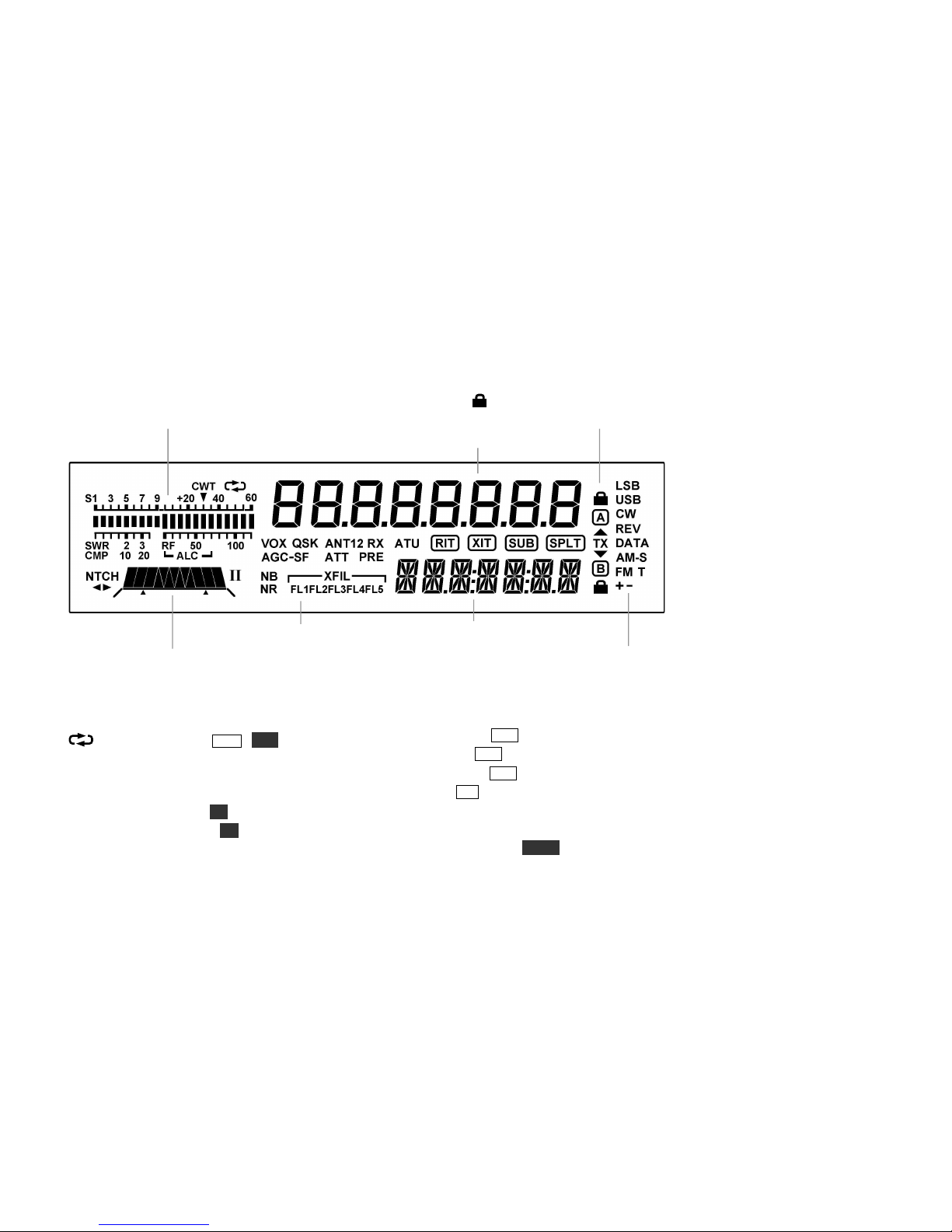
Display (LCD) (For Details, refer to page numbers shown in parentheses)
RX: S-meter and CW tuning aid (18);
TX: SWR/RF output or compression/ALC (19)
VFO Icons: Shows that a VFO is locked.
TX icon points to the transmit VFO, A or B (30).
VFO A
XFIL (FL1 only in KX2)
VFO B
Filter Passband Graphic (17):
NTCH Auto-notch (18); I/II (not used)
Mode Icons
Other icons:
CWT CW/data tuning aid on (MENU:CWT, 18)
Message play/rec (MSG / REC, 19, 30), or
logging enabled (MENU:LOGGING)
VOX VOX enabled (MENU:VOX MD, 20, 21)
QSK Full break-in CW (MENU:VOX DLY,21)
NB Noise blanker on (NB, 18)
NR Noise reduction on (NR, 18)
ANT KXPA100 antenna (19)
RX Automatic RX attenuation in effect (17)
ATT Attenuator on (PRE, 17)
PRE Preamp on (PRE, 17)
ATU ATU enabled (ATU, 19)
RIT RIT on (RIT, 16)
XIT XIT on (MENU:XIT, 16)
SUB Dual-watch enabled (MENU:DUAL RX, 25)
SPLT Split mode in effect (SPLIT, 30)
14
Basic Operation
This section describes basic KX2 features. Once
you’ve mastered these, you’ll be ready to explore
Advanced Operating Features (pg. 23) including
built-in text decode, memories, and dual watch.
Getting Started
Before using the KX2, you’ll need to connect a power
supply and an antenna. See Installation (pg. 5).
Turning the KX2 On/Off
To turn the KX2 on or off, press and hold the RATE
and A/B switches simultaneously for about two
seconds, then release. The switches are identified by an
“ON” label below the large knob (VFO A). This dualswitch power on/off method reduces the likelihood of
accidental power-on in a backpack or carrying case.
Always turn the KX2 off as described above
before turning off or disconnecting the power
source. This will ensure that settings are saved.
Switch TAP and HOLD Functions
All KX2 switches have two functions:
§ Tap to activate the function labeled on a switch,
e.g. RATE
§ Hold for about 0.5 second to activate the function
labeled below a switch, e.g. FREQ
AF Gain and other Knob Functions
Each small knob has two primary functions. For
example,
AF/MON normally controls receiver AF
gain. The setting is displayed in the VFO B area during
knob rotation. Tapping this knob briefly switches to
the MON function (sidetone or voice monitor level).
Holding the knob—pushing it for over 0.5 seconds—
switches to its secondary function,
NB (pg. 18).
Knobs may also be used in conjunction with nearby
switches. For example, if you tap DISP, rotating
OFS/B selects special VFO B displays (pg. 23).
Using the Configuration Menu
To access the menu, hold MENU until the
BKLIGHT (LCD brightness) menu entry appears in the
VFO B area. The setting appears in the VFO A area.
To change a setting, rotate VFO A (large knob). In the
case of BKLIGHT, this selects backlight ON or OFF.
To scroll through menu entries, use the small knob
above the menu switch,
OFS/B. To exit the menu,
tap DISP.
While in the menu, holding MENU for ~3 seconds
displays information about the current menu entry.
Configuration and Calibration Functions
Once you’ve mastered the menu, you should review
your KX2’s Configuration settings (pg. 36). The
menu is also used for factory Calibration (pg.38).
15
Band Selection
The KX2 transmits and receives in the 80-10 m
amateur bands. It also provides general coverage
receive from 0.5 to 32 MHz, which includes the AM
broadcast band and 160 m.. (Sensitivity and image
rejection are reduced below 3 MHz; see
Specifications, pg. 68.)
Characteristics of each amateur band are briefly
summarized below. For further information, see the
ARRL band plan (www.arrl.org/band-plan-1).
To change bands: Tap BAND, rotate the VFO A knob
to select the desired band, then tap any switch to exit.
You can also change bands using direct frequency
entry (described at right) and memory recall (pg. 24).
Band
(m)
Range
(MHz)
Best
DX
Other
Characteristics
160
1.8-2.0
(RX only)
Night
Challenging “Top Band”; high
power often used to counter noise
80
3.5-4.0
Night
Excellent regional band; many
CW and SSB nets; AM ~3.870
60
~5.3-5.4
Night
Shared with government services;
power level and modes restricted
40
7.0-7.3
Night
Excellent local CW/SSB band by
day; QRP & data modes, 7.03-7.04
30
10.1-10.15
Both
DX possible anytime; no contests
20
14.0-14.35
Both
Very popular DX & contest band;
many nets on SSB; Data modes:
PSK ~14.070; RTTY ~14.085
17
18.068-
18.168
Day
Long-haul DX band; no contests;
“HF Pack” at 18.1575 (often QRP)
15
21.0-21.45
Day
DX/contest band; low power very
effective when band is open
12
24.89-24.99
Day
Excellent DX band; no contests
10
28.0-29.7
Day
Great QRP DX band; CW beacons
(28.2-28.3) show if band is open
Direct Frequency Entry
A subset of the controls functions as a numeric keypad
for use with FREQ. See white secondary switch and
knob labels 0 - 9, decimal point, and enter ( ).
First, hold FREQ . Then enter one or two MHz digits,
optionally followed by a decimal point and up to three
kHz digits. Next tap . (BAND) to accept, or any
other switch to cancel. Examples:
14.255 MHz: FREQ 1 4 . 2 5 5 . . .
7.000 MHz: FREQ 7 .
Mode Selection
Tap MODE to select SSB, CW, or AM mode. Tap
DATA to select data mode (pg. 15). To select alternate
modes (USB/LSB, CW normal/reverse, or DATA
normal/ reverse) use the ALT MD menu entry.
SSB (pg. 20) is either LSB (lower sideband) or USB
(upper sideband). LSB is normally used on 160, 80,
and 40 m, while the other bands normally use USB.
CW mode (pg. 21) uses much less bandwidth than
SSB, providing a high signal-to-noise ratio ideal for
low-power (QRP) operation.
AM mode (pg. 22) has a characteristic “warm” tone. It
can be used for listening to broadcast stations.
DATA modes (pg. 27) are often used with a computer
connected to the KX2 to send/receive text. However,
there are also three built-in data modes that use the
KX2’s display for received text, and a keyer paddle for
transmit, converting the CW you send into data.
16
VFO A and B
The KX2 provides two VFOs (see glossary, pg. 66).
Each VFO has its own frequency, mode, and filter
settings. Use of VFO B (
OFS/B) is optional.
VFO A normally controls both the receive and
transmit frequency. If you use VFO A to tune in a
signal clearly, you’ll also be on-frequency for transmit.
VFO B can serve as a holding register for a frequency
of interest (see A / B swap below). It is also used with
SPLIT (pg. 30) and Dual Watch (pg. 25). To tune
VFO B, first make sure the B LED above the knob is
lit. If not, tap the
OFS/B knob.
Tuning rates: Tapping RATE normally alternates
between 10 Hz and coarse-tuning steps (MENU:VFO
CRS). The default coarse step size for CW is 0.1 kHz,
and for SSB, 0.5 kHz. In DATA modes, or when the
audio peaking filter is in use in CW mode (APF, pg.
18), RATE alternates between 1 Hz and 10 Hz steps.
OFS/B is used to tune VFO A in coarse steps.
For this purpose, the OFS LED must be lit (if not, tap
the knob), and RIT (see at right) must be turned off.
To lock VFO A: Hold FREQ for about 3 seconds. Tap
RATE to unlock. To lock VFO B, first swap it with
VFO A, lock A, then swap again.
To copy VFO A’s frequency to VFO B: Hold
A > B. Tap twice to copy mode and filter settings as
well.
VFO A and B swap: Tap A / B to exchange VFO
frequencies, modes, and all other settings.
Incremental Tuning (RIT and XIT)
RIT, or receive incremental tuning, adjusts the receive
frequency without affecting your transmit frequency.
RIT is sometimes called a clarifier since it can be used
to tune in voice signals clearly. It is also useful in CW
and DATA modes when a station calls off-frequency.
XIT, or transmit incremental tuning, adjusts the
transmit frequency without affecting the receive
frequency. (An alternative is to use SPLIT, pg. 30.)
∆ F (Delta-F) LED : This LED turns on whenever
RIT, XIT, or SPLIT is in use as a reminder that your
receive and transmit frequencies may be different.
To use RIT: First, tap RIT . This turns on the RIT
icon and the OFS LED. Adust using
OFS/B .
To use XIT: XIT is controlled using MENU:XIT.
Setting the menu entry to ON turns on the XIT icon
and the OFS LED. Adjust using
OFS/B .
To zero the RIT/XIT offset: Hold CLR.
You can still use the
OFS/B control to tune
VFO B, even if RIT or XIT is turned on. Just tap the
knob to turn the B LED back on. The RIT/XIT icons
on the LCD will retain their current states.
Special VFO B Displays
To see special information on VFO B, tap DISP , then
rotate
OFS/B. Available displays include time,
supply voltage, supply current, amp hours used, logged
text review, etc. (see pg. 23).
17
Receive Settings
The Receive controls group, which includes the
AF/MON knob and the two switches below it, is
used to set up the KX2’s receiver. On the display,
directly above these controls, is the filter passband
graphic. This shows the receiver’s audio passband.
AF Gain / Monitor Level Control
The
AF/MON knob normally controls receiver AF
gain. Tapping the knob switches its function to MON
(monitor volume level). In CW mode, this turns on the
sidetone (also see Spot, pg. 21). In SSB mode, you’ll
hear your microphone audio (pg. 17).
Switch activation tones, if used, have the same
volume level as the CW sidetone (as set in CW mode
using
MON ). Switch tones can be set to off, on, or
Morse code characters (MENU:SW TONE).
Preamp and Attenuator
On successive taps, PRE cycles through preamp on
(attenuator off), both off, and attenuator on (preamp
off). PRE and ATTN icons are updated accordingly.
Typically the preamp is used on the higher bands or
with low-gain antennas. If interference is heavy, turn
the preamp off, and if necessary, turn the attenuator on.
You can improve sensivitity by using the internal
ATU to resonate the antenna. Tap ATU.
The KX2 will automatically reduce receive gain in
the presence of very strong signals. The overload icon
(RX) will turn on. Also see MENU:COR LVL.
Filter Passband Control
Tapping FIL places the KX2 in FIL ADJ mode. In
this mode, the
AF/MON and KYR/MIC knobs
can be used to adjust the filter passband as described
below. Settings are stored per-mode.
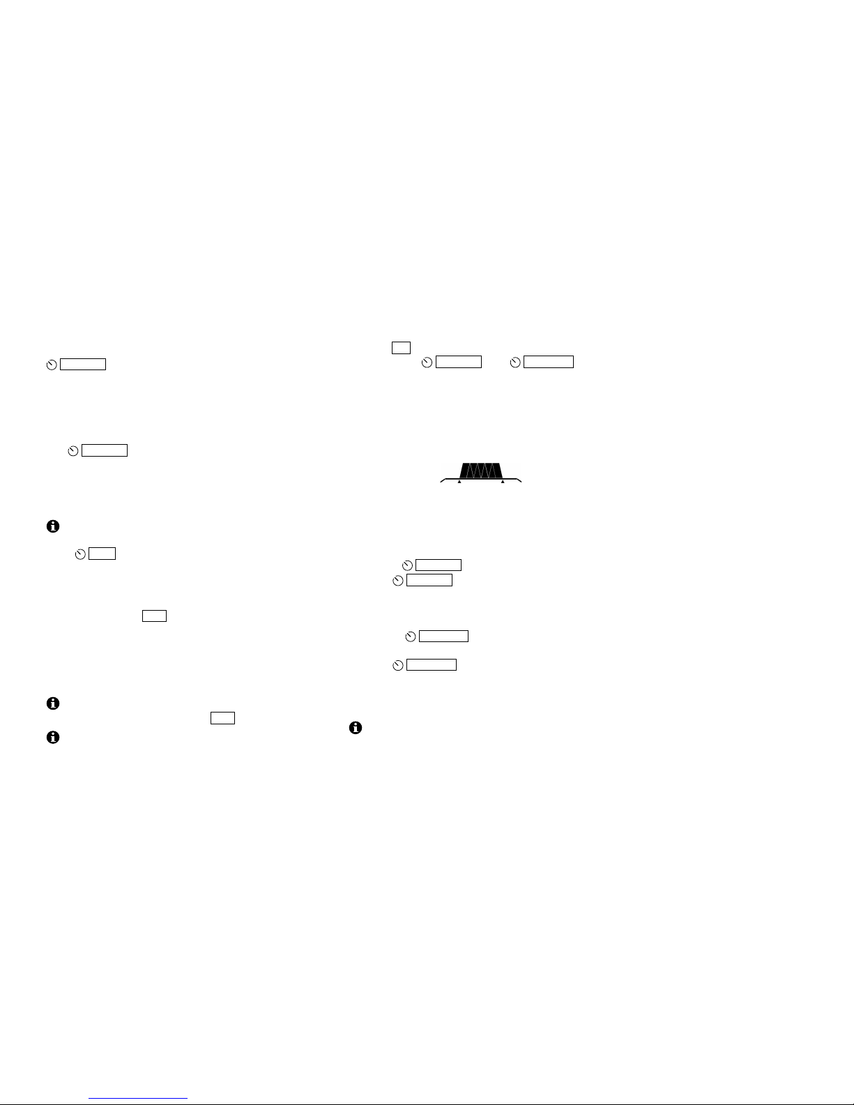
The passband graphic shows an approximation of the
width and centering of the current filter. The example
below shows a medium-width filter that is centered
(not shifted):
In general, a narrow passband reduces interference
(QRM) and noise (QRN), while a wider passband can
reduce listening fatigue and improve fidelity.
Using FIL ADJ mode:
• Rotate
AF/MON knob to adjust the filter width.
• Tap
AF/MON to normalize the filter to the
standard per-mode setting. This turns on the two
“wings” shown at the left and right ends of the
graphic as shown above.
• Rotate
KYR/MIC to shift the passband left or
right.
• Tap
KYR/MIC to center the filter without
changing the bandwidth.
• To exit FIL ADJ mode, tap any other switch, key
the transmitter, or rotate VFO A.
Filters in the KX2 are implemented entirely within
the digital signal processor (DSP).
18
Noise Reduction
Noise reduction (NR) removes random background
noise (hiss or static). It has a characteristic “hollow”
sound. Higher settings may attenuate weak signals.
Holding NR turns on noise reduction and displays its
setting, which can then be adjusted using the knob
above the switch. Tap any switch to exit the setting
display. Hold NR again to turn noise reduction off.
Noise Blanking
Noise blanking can eliminate repetitive noise such as
that from power lines, appliances, and vehicle ignition
systems. Use the lowest effective setting.
Holding NB (a function of the
AF/MON knob) turns
on the noise blanker. The setting can then be adjusted
using this knob. Tap any switch to exit the setting
display. Hold NB again to turn the blanker off.
Audio Peaking Filter (APF) and Notch Filter
In CW mode, holding APF- AN turns on a very narrow
filter to improve copy of weak CW signals right at the
receiver’s noise floor. The filter graphic changes as
shown below, and VFO tuning is set to 1 Hz.
In SSB and AM modes, APF- AN turns on auto-notch
(AN). Auto-notch can suppress one or more audible
carriers (continuous tones) automatically, while having
little impact on speech signals.
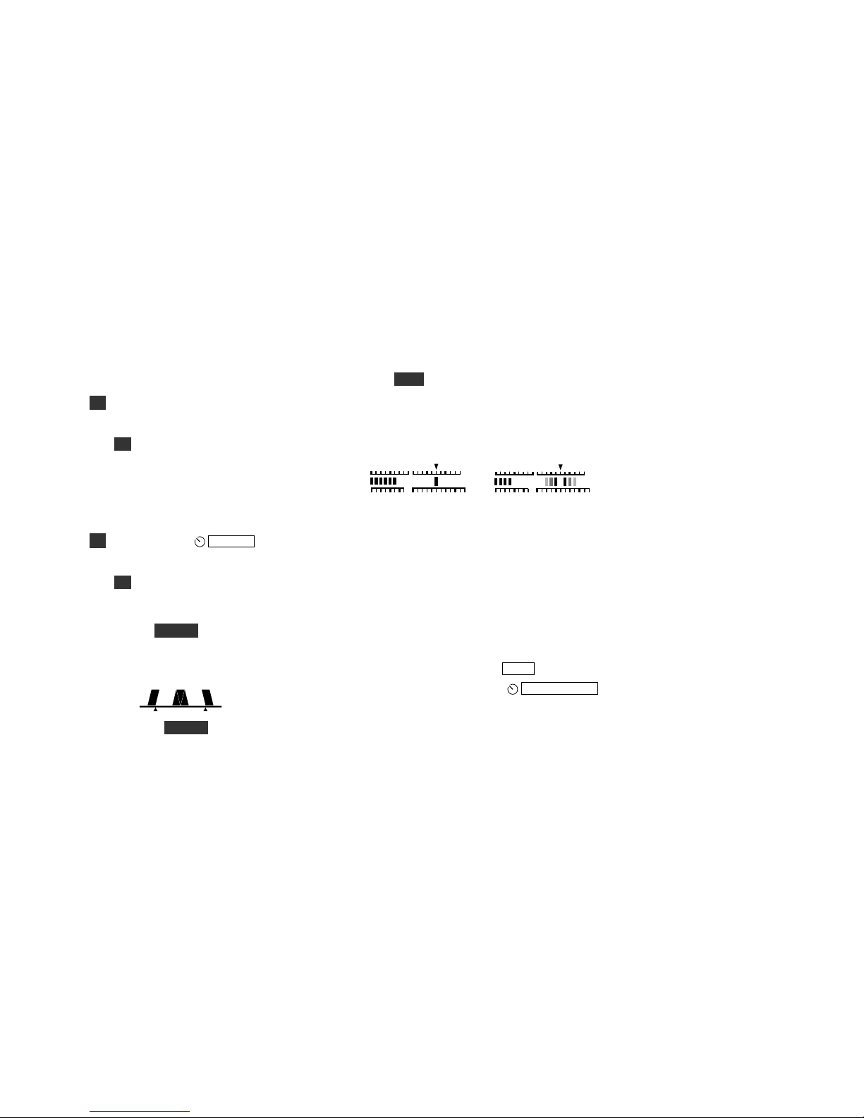
CW/DATA Tuning Aid (CWT)
Accurate tuning of received signals is required before
you call a station, or when you’re using built-in text
decode (TEXT, pg. 21). Signals can always be tuned in
by ear, but the KX2 also provides a visual tuning aid
(CWT). With CWT on (MENU:CWT), the upper half
of the S-meter changes as shown below.
CW and PSK31/PSK63 RTTY
A CW signal appears as a single bar. Tune the signal
until the bar is centered beneath “CWT” as shown.
This single-bar display also applies to PSK-D (pg. 28).
In RTTY or radioteletype modes, mark and space tones
appear as bars on either side of the CWT pointer (see
FSK D and AFSK A data modes, pg. 28). With no
signal, you’ll see a “ghosting” effect (above). As you
tune in a signal, solid bars will appear on both sides.
To optimize CW/data text decode, you may need to
fine-tune the VFO position. This is especially true in
PSK-D mode. Use 1 Hz steps (RATE).
Spot and Auto-Spot: Tapping
KYR-SPT/MIC
generates an audible spot tone in CW, PSK-D, and
FSK-D modes. Tune the VFO until the signal pitch
matches the spot tone. If CWT (see above) is turned on
in CW and PSK-D modes, tapping this knob will tune
in the signal automatically, if possible (auto-spot).
50
100
23SWR
RF
CWT
S135
7
9
50
100
23SWR
RF
CWT
S135
7
9

19
Transmit Settings
The Transmit controls group (to the left of the VFO A
knob) is used to set up the KX2’s transmitter. The
nearby TX LED turns on during transmit.
This section provides an overview of transmit
controls. Detailed per-mode instructions follow.
Keyer Speed-Spot/Mic Gain and Power Output
In CW mode,
KYR- SPT/MIC sets the keyer speed
(in WPM). Tapping the knob spots a signal (pg. 21). In
SSB mode, this knob sets mic gain. A typical seting is
15-25 for use with the Elecraft MH3 microphone.
Holding this knob for ~0.5 seconds selects
PWR
(power output control). Power level is shown on the
RF bar graph during transmit. Maximum power output
is typically 10 W on 80-17 m, and 8 W+ on 15-10 m.
A power supply voltage of 12 V or higher is
recommended for SSB use at full power.
If a KXPA100 amplifier is connected, power can be
set up to 100 W (see KXPA100 owner’s manual).
The right side of the KX2 may become quite
warm during transmit. If the amplifier temperature is
too high, power will be automatically reduced.
Maximum power output varies with supply
voltage and other factors. If output is lower than
expected, use the special VFO B displays (pg. 23) to
check supply voltage, current drain, and PA
temperature. The selected parameter will be shown on
VFO B during TUNE. (SWR is shown on VFO A.)
Transmit Controls and ATU Tuning
Tap
AF/MON to set the transmit monitor volume
(speech in voice modes, sidetone in CW mode).
XMIT switches from receive to transmit. However, in
CW modes, MENU:VOX MD is usually set to ON, so
you can simply hit the key or keyer paddle to transmit.
(VOX is always on in PSK-D/FSK-D modes.) In SSB
mode, tapping XMIT is an alternative to using mic PTT
or VOX. (See pg. 20 for SSB VOX setup.)
TUNE is used to transmit a CW signal at the power
level selected by the
PWR control. This is useful
with external wattmeters and antenna tuners. The
TUN PWR menu entry can be used to override the
PWR control setting and transmit at a lower level.
ATU starts automatic antenna matching if a KXAT2
internal ATU is installed (pg. 19), or if a KXPA100
amp with KXAT100 ATU is connected (pg. 33).
MENU:ATU MD must be set to AUTO. Matching
takes an average of 4 seconds, initially. Settings are
recalled on band change, or when you transmit after
moving the VFO a significant distance. The ATU icon
flashes briefly when settings are recalled. In CW mode,
recall is delayed until a pause in keying. Also see
MENU:ATU DATA for selection of ATU data sets.
With difficult loads, try tapping ATU a second
time within 5 seconds to search for a lower SWR.
PFn (programmable functions): See pg. 25.
MSG and REC are used to play and record CW, data,
or digital voice messages (pgs. 22 and 30).
20
SSB Mode
Use the steps below to do initial SSB setup:
§ Set PWR to 0.0 W.
§ Tap MODE to select SSB (either LSB or USB).
To change SSB modes, use MENU:ALT MD.
§ Tap
AF/MON to set the voice monitor level.
Start with 3. High settings may sound distorted.
§ Set MENU:TX CMP (speech compression) to 0
initially. Exit the menu.
§ Tap XMIT or hold in the mic’s PTT switch. Note:
Hand-held mics like the Elecraft MH3 should
nearly touch your mouth when you are speaking.
§ While speaking into the mic, adjust mic gain
( MIC). This will turn on the transmit CMP and
ALC bar graphs. While speaking, adjust mic gain
for about 5 ALC bars (see below). Mic gain for
the Elecraft MH3 is typically set to 15-25, and
30-40 for the internal mic.
§ To use speech compression, set MENU:TX CMP
to 10-20 initially. Compression increases average
“talk power” with only slightly decreased fidelity.
§ Exit transmit mode. Set PWR to the desired
level. Do not use MIC gain to set power level.
Set mic gain to a fixed level as described above.
VOX Setup
Several menu entries are used to configure SSB VOX
(voice-operated transmit):
If MENU:VOX MD is OFF (PTT, or push-to-talk
mode), the transmitter must be enabled by tapping
XMIT or by holding the mic’s PTT button. With VOX
on, the VOX icon turns on, and transmit starts by
speaking. If VOX is on, the remaining menu entries
below should also be set up.
VOX cannot be used with the built-in
microphone. Use the XMIT switch to transmit.
MENU:VOX GN (VOX gain) should be set to trigger
at normal speech level, but not in response to
incidental noise. Start with low settings (10-20).
MENU:VOX DLY sets the VOX (voice-operated
transmit) delay time in seconds. A setting of about 0.5
seconds will keep the radio in transmit mode during
typical continuous speech.
MENU:VOX INH (VOX inhibit, or anti-vox) can
prevent speaker audio from triggering VOX.
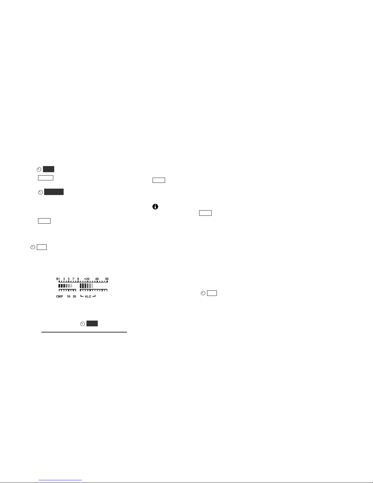
Transmit Metering
In SSB mode, tapping MIC switches the transmit
bar graph from SWR / RF to CMP / ALC.
The CMP / ALC scale is selected automatically when
you adjust mic gain or speech compression. The
SWR / RF scale is restored after a few seconds.

21
CW Mode
Basic CW-Mode Setup
§ Tap MODE to select CW (normal CW mode).
Some operators prefer to use CW reverse (CW
REV). See MENU:ALT MD for details.
§ MENU:VOX MD can be set to ON (VOX) or OFF
(PTT) for CW mode. Most operators use VOX,
allowing the transmitter to be keyed immediately
whenever a hand key or keyer paddle is used. PTT
requires manual transmit start/stop using XMIT.
§ Set sidetone pitch using MENU:PITCH. 500-700
Hz is typically used with headphones.
§ Set sidetone volume using
MON.
§ MENU:VOX DLY sets the break-in or QSK delay
(the time before the receiver recovers after keyup). A setting of 0.00 provides full break-in, also
known as “full QSK.” (The QSK icon will appear.)
MENU:CW WGHT provides two variations on
QSK; CW operators may wish to try both.
CW Receive Filtering
As conditions change, you can adjust the filter
passband using FIL as described on pg. 17. A narrow
passband can improve copy in the presence of noise or
interference, while a wider passband can be less
fatiguing to listen to. You’ll also find the audio
peaking filter (APF, pg. 18) to be very useful with
weak CW signals.
Off-Air Code Practice
Sending CW normally produces both a sidetone and a
transmitted signal. If PTT-CW is selected (by setting
MENU:VOX MD to OFF), hitting the key without
first tapping XMIT will generate only a sidetone. This
is useful for code practice or keyer speed adjustment.
CW-Mode Menu Settings
You can use the menu to change the settings for iambic
keying (CW IAMB), keying weight (CW WGHT), and
paddle normal/reverse or hand key (CW KEY1 for the
KEY jack, and CW KEY2 for an attached KXPD2 or
KXPD3 keyer paddle).
CWT, SPOT and Auto-Spot
When calling a station, you should try to match your
frequency to theirs. To facilitate this, the KX2 provides
both a visual tuning aid (CWT), as well as manual and
automatic spotting in CW and some data modes. See
pg. 18.
CW Text Decode/Display
The KX2 can decode transmitted and received CW
signals, displaying the text on VFO B (pg. 29). This is
especially useful when you’re learning CW, or if
someone who doesn’t know CW is looking over your
shoulder while you make CW QSOs. It’s also
indispensable for CW-to-DATA operation (pg. 27).
The KX2 can also capture transmitted CW for logging
purposes. See MENU:LOGGING.

22
CW/DATA Message Record/Play
There are 3 text messages, each having up to 250
characters. These apply to CW as well as DATA
modes FSK D and PSK D.
Messages can only be recorded using the KX2’s
built-in keyer function (using either an external keyer
paddle, KXPD2, or KXPD3). An external keyer cannot
be used. Messages can also be viewed or edited using
the KX2 Utility computer application.
Message Record: To start recording, hold REC , then
select a message by tapping any of switches 1 through
3 of the numeric keypad (the PRE, FIL, and ATU
switches, respectively). The remaining text space will
be displayed as you send. Tap MSG to finish
recording.
Message Play: To play, tap MSG , then select a
message (1 through 3). To cancel, tap XMIT or hit the
keyer paddle or hand key.
Message Erase: Hold REC, select a message (1
through 3), then hold CLR.
Auto-Repeat: To auto-repeat a message, tap MSG ,
but then hold rather than tap a message switch (1
through 3). MENU:MSG RPT sets the message
repeat interval (1 to 255 seconds). To cancel autorepeat, tap XMIT or hit the keyer paddle or hand key.
Chaining: Tapping a message switch during playback
chains another message onto the message being played.
Holding a message switch during playback chains a
repeating message.
AM Mode
To select AM, tap the MODE switch.
To disable AM mode, use MENU:AM MODE.
AM Receive: AM mode can provide a “warmer”
sound that SSB mode when used to copy shortwave
broadcast stations. Also, VFO tuning is less critical.
MENU:VFO CRS provides coarse-tuning selections
of 1, 5, 9 and 10 kHz for AM mode.
A good place to look for AM amateur signals is around
3.870 MHz at night.
AM Transmit: Setup for AM transmit is the same as
for SSB (pg 20). However, speech compression should
in general be turned off for AM mode (MENU:TX
CMP). The RF bar graph will indicate about 1/3 to 1/2
the power set by the power control.
AM is far less power-efficient than SSB, so at QRP
levels, SSB is preferred for most communication
purposes.

23
Advanced Operating Features
Special VFO B Displays
The KX2 can display time of day and other parameters
on the VFO B display. To access these displays, tap
DISP , then rotate the OFS/B control.
The following special displays are available:
§ 24-hour time, obtained from the real-time-clock
on the KXIO2 option module. If a KXIO2 is not
installed, the time since last power-on will be
displayed. Set the time using MENU:TIME.
§ Power supply voltage. If you have both an
internal battery and an external power source
connected to the KX2, the display will show the
higher of the two voltages. This display, as well as
the next two, stay visible even when using TUNE,
so you can check key-down conditions.
§ Supply current. Typical receive-mode current is
0.15-0.20 A. It can be reduced by turning off the
LCD backlight and preamp, and by using
headphones. Transmit current is typically 1 to 3 A.
§ Power Amplifier (PA) temperature. The KX2’s
internal PA temperature is shown as PA.I nnC
(Internal). If a KXPA100 is connected via the
remote-control cable, MENU:PA MODE is ON,
and
PWR is set to > 10 W, the KXPA100’s PA
temperature is shown, as PA.X nnC (eXternal).
PA temperatures rise gradually as you transmit.
§ Audio Signal level (AFV). Shows the KX2’s
audio output level, prior to the AF gain control
(the AF gain control has no effect on this reading).
The reading will vary with preamp and attenuator
settings. AFV is used along with dBV (below).
§ Relative audio signal (dBV). Used to measure
receiver sensitivity or or to compare signals. First
select AFV (described above) and allow the
voltage reading to stabilize. (This may not be
possible with rapidly changing signals.) Once the
signal appears stable, select dBV. You should now
see a reading of around 0 dBV (see Glossary)
relative to the last AFV reading. If you change the
setting of the preamp or attenuator, you should see
this reading change. However, it may not change
as much as you expect unless you also turn AGC
off using the AGC menu entry. (Be sure to turn
AF gain down before turning AGC off, as the
signal may become very loud.)
§ Amp hours: Shows total amp hours used since
the value was last reset (for details, see
MENU:AMP HRS). Used to test batteries or
estimate remaining battery charge.
Hold CLR while in the AMP HRS menu
entry to zero the amp hours value.
§ Log Data: Use VFO A to scroll through recorded
outgoing CW/DATA text. Also shows time stamps
and band/mode. See MENU:LOGGING.
Hold CLR to erase all log data.
 Loading...