

Page 1
Elecraft K3
KSYN3 DDS Gain Modification
Revision A1, May 27, 2010
Copyright © 2010, Elecraft, Inc., All Rights Reserved
The KSYN3 synthesizer uses a direct digital synthesizer (DDS) circuit. In rare cases, at certain frequencies the
DDS driving signal to the Phase Locked Loop (PLL) may be marginal, resulting in a sudden shift in frequency
(commonly called “chirp”). This modification adds a resistor to the KSYN3 board that increases the DDS drive
level prevent this condition. This is an optional modification and is not required unless you are experiencing this
condition.
If you chose to make this modification and your K3 is equipped with the KRX3 subreceiver it will have two
KSYN3 synthesizers. Although only the main synthesizer is used for transmitting, both boards should be
modified to in case they are reversed at some future date.
This modification involves adding a single leaded resistor to the pc board. No SMD work is required. If needed,
the resistor may be ordered from Elecraft. See Parts Required below.
Tools Needed
A temperature controlled ESD-safe soldering iron with a fine tip and fine rosin core solder, diagonal cutters and
Phillips screwdrivers for opening the case and a DMM for making resistance measurements. An ESD wrist strap
is strongly recommended.
Does My K3 Have This Modification?
If the modification was made using a leaded resistor as described in this document, the resistor will be visible on
the side of the KSYN3 board closest to the front panel shield. You need to loosen the KSYN3 board mounting
screws and tilt the board away from the front panel shield slightly to see the resistor. If the resistor is not
present, you may have a board that was modified at the factory by replacing a SMD resistor. In that case,
measure the actual resistance as described under Installing the New Resistor on page 3.
Parts Required
Photo Description Quantity Part
Number
Resistor,51 ohms, 1/8 watt, (grn-brn-blk) 1 E500415
Elecraft • www.elecraft.com • 831-662-8345
Page 2
Removing the KSYN3 Board(s)
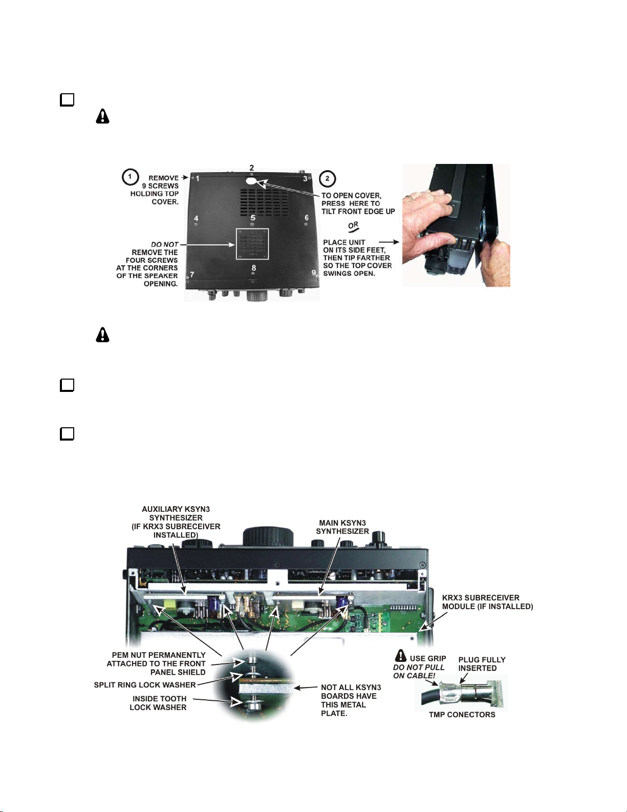
Remove the K3 top cover as shown in Figure 1.
Whenever you remove screws from a panel, if one screw seems too tight to loosen
without damaging it, first loosen the other screws then try again. Sometimes one screw
binds in its hole when the other screws are tightened
Figure 1. Removing the Top Cover.
.
CAUTION:
before touching components or circuit boards inside the K3.
If you are modifying the main KSYN3 board (see Figure 2) and the K144XV 2-meter option is installed,
remove the K144XV module. Remove the three screws securing it to the right side panel. You can move it out
of the way while removing the synthesizer or you can unplug the connectors and set it aside.
Remove the KSYN3 board(s) to be modified (see Figure 2). If the optional K144XV 2-meter module is
installed, remove it to gain access to the mounting screws for the main KSYN3 board. Each board plugs into the
RF board on bottom of the K3 and is held in place with two screws at the top. Loosen the screws and tip the
boards to remove the split lock washers. Unplug the TMP coaxial cables as you lift each board out. The TMP
connectors are held by friction. Pull only on the metal ears of the TMP plug. Do not pull on the coaxial cables.
Touch an unpainted metal ground or wear a grounded wrist strap
Figure 2. Removing the KSYN3 Boards.
K3 KSYN3 Gain Modification Page 2 of 5
Page 3

Installing the New Resistor
Use your DMM to check the resistance of R20. R20 is shown in Figure 3 below. If the resistance is close to
25 ohms your synthesizer has already been modified. Do not install the 51 ohm resistor. If the resistance is about
50 ohms, install the 51 ohm 1/8 watt resistor (grn-brn-blk) across it as shown in the figure. Note that:
One end of the leaded resistor is connected directly to R20. Do not hold your iron on the connection for
more than one or two seconds. Longer times may cause the SMD to pop off of the board. It is a 51 ohm
resistor and the low value allows heat to conduct quickly, desoldering both ends at once. Tin the lead on
your resistor first, then while holding it in place, quickly tack it onto the end of R20
The other end of the leaded resistor is soldered to a via (plated hole) in the KSYN3 board. This hole
may be open or already filled with solder. It is not necessary (or desirable) to poke the lead through the
via. If via is open, trim the lead so it will just enter the via without passing all the way through. If the via
is already filled with solder, lay the lead against the existing solder and tack it in place just as you did
with the end at R20.
Figure 3. New Resistor Installed on KSYN3 Board.
K3 KSYN3 Gain Modification Page 3 of 5
Page 4

Reassembling the K3
Replace the KSYN3 board(s) in the K3, ensuring all the pins of the multi-pin connectors mate properly
with the connectors on the RF board. Secure the KSYN3 assemblies to the front panel shield with the hardware
shown in
panel shield. This washer is required to ensure proper spacing between the KSYN3 board and the shield. If your
K3 did not have washers installed here, washers are included with his mod kit. Do not use inside tooth lock
washers behind the board. They are large enough to short out to nearby traces and solder pads on the KSYN3
board.
Figure 4 at each top corner. Note that a split ring lock washer is used between the board and the front
Figure 4. KSYN3 Assembly Mounting Hardware.
Reconnect the TMP cables to the KSYN3 board(s) as shown in Figure 5. Ensure all the cables are properly
seated.
Figure 5. TMP Cable Connections
K3 KSYN3 Gain Modification Page 4 of 5
Page 5

If your K3 is equipped with the K144XV 2-meter option, replace the module. Refer to Installing the
K144X V in the K3 in your K144XV Installation and Operation manual for details on reconnecting the
cables and mounting the module.
Hold the top cover above the K3, route the speaker wire under the stiffener bar and plug it into P25 on
the KIO3 board at the left rear of the K3 as shown in Figure 6. If the K144XV module is installed, the
cable connector will fit under the stiffener bar at the dimple in the top of the K144XV module.
Figure 6. Connecting Speaker Cable.
Replace the nine flat head screws in the top cover shown in Figure 1.
IMPORTANT: The cabinet screws are essential for the K3 shielding to work properly.
Leaving one loose may result in unwanted birdies in the receiver and other hard-totroubleshoot problems.
Update Firmware. This modification requires firmware rev 3.88 or later, available from the Elecraft
web site (www.elecraft.com). This revision controls the DDS range to ensure correct operation.
This completes your KSYN3 Synthesizer Modification.
K3 KSYN3 Gain Modification Page 5 of 5
 Loading...