

ELECRAFT K-POD Owner's Manual
ELECRAFT
CONTROL PANEL
OWNER’S MANUAL
Rev D, October 17, 2016
Copyright © 2016, Elecraft, Inc.
All Rights Reserved
E740285
K•POD

2
Important – read carefully
Operating tip
CONFIG:SQ MAIN
Typical K3/K3S menu entry
Key to Symbols and Text Styles

3
Contents
Key to Symbols and Text Styles ............................................................................................................... 2
Introduction ............................................................................................................................................... 5
In the Box ................................................................................................................................................. 5
Installation ................................................................................................................................................ 5
Placing the K-Pod ............................................................................................................................................... 5
Adjusting the Knob Drag .................................................................................................................................... 5
Data Connection .................................................................................................................................................. 6
Optional Power Connection ................................................................................................................................ 7
USB Interface to PC ............................................................................................................................................ 7
Auxiliary Outputs ................................................................................................................................................ 7
Controls and Indicators ............................................................................................................................. 7
Operating the K-Pod ................................................................................................................................. 8
Controlling a K3S/K3 from the K-Pod ............................................................................................................... 8
Contest Operation Macros ............................................................................................................................... 8
DXer Macros ................................................................................................................................................... 9
DX-Pedition Macros ..................................................................................................................................... 10
Data Mode Macros ........................................................................................................................................ 11
General Use Macros ...................................................................................................................................... 11
Controlling the K-Pod LEDs and Auxiliary Outputs ........................................................................................ 12
Examples of Controlling the Auxiliary Outputs............................................................................................ 12
Controlling your PC from the K-Pod ................................................................................................................ 13
Firmware Upgrades ................................................................................................................................ 14
Connecting the K-Pod To your Computer ........................................................................................................ 14

4
Customer Service and Support .......................................................................................................................... 15
Technical Assistance ..................................................................................................................................... 15
Repair / Alignment Service ........................................................................................................................... 15
Appendix A: Modifying Earlier K3S and K3 Transceivers to Power the K-Pod through the Data
Connector. ............................................................................................................................................... 16
Introduction ....................................................................................................................................................... 16
Parts and Tools Required .................................................................................................................................. 16
Procedure .......................................................................................................................................................... 16
Removing the K3 or K3S Front Panel Assembly.......................................................................................... 16
Installing the Modification and Reassembling the Transceiver. ................................................................... 18
Appendix B: Data Cable Wiring ............................................................................................................ 19
Appendix C: K3S/K3 Macro Basics ....................................................................................................... 20
Switch Macros ................................................................................................................................................... 20
Knob (Encoder) Macros .................................................................................................................................... 21
Other Macros ..................................................................................................................................................... 21
Elecraft manuals with color images may be downloaded from
www.elecraft.com.

5
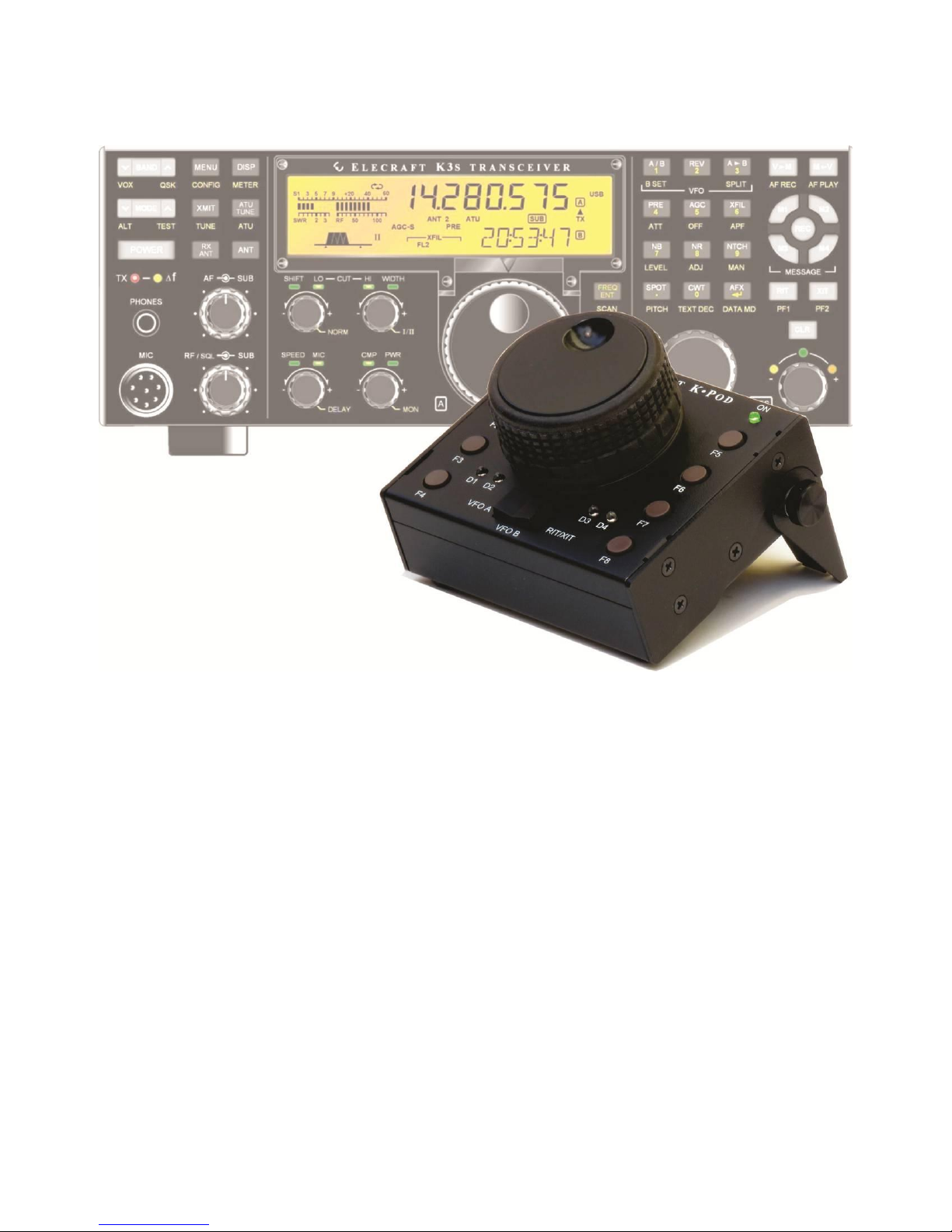
Introduction
The K-Pod control panel is an ideal companion to your Elecraft K3 or K3S transceiver, maximizing convenience
and operating efficiency. It’s small enough to be placed anywhere the action is, typically next to a computer
keyboard. It’s versatile enough to integrate multiple transceiver and station control functions.
Features include:
A heavy, free-spinning knob that can be assigned to VFO A, VFO B, or RIT/XIT offset.
Control of 16 functions using tap and hold operation of 8 programmable switches.
Switch functions can be easily set up using K3 Utility to perform diverse functions such as selecting
bands, modes, frequencies, or power levels; sending messages; clearing RIT; changing tuning rates, etc.
Many examples are provided in this manual.
Additional capabilities will be provided with future firmware releases, such as direct control of the unit’s three
general-purpose relay drive outputs.
In the Box
K-Pod module.
DC Power Cable, 2.1 mm Barrel Connector to RCA Connector, 24” (61 cm), E850427
K3S/K3 Data Cable, 6P6C Connectors, 30” (76 cm), E980326
Cable, USB A to B Connector, 36” (91 cm), E850629
Allen Wrench (for Knob Set Screw), 5/64” (2 mm), E980004
K3 Modification Kit (for some older K3 Transceivers, see page 16), E850755
Installation
Placing the K-Pod
The K-Pod module may be operated in any position. A built-in tilt stand may be deployed by loosening the two
thumb screws to hold it at a convenient angle (see image on page 1). In addition two threaded holes for 8-32
screws are provided for mounting it on a user-supplied bracket or support.
Adjusting the Knob Drag
Friction to limit the ease with which the knob turns is provided by two felt washers between the knob and the
K-Pod panel, just as is done on the K3S or K3 VFO A knob.
To adjust the friction, remove the finger grip to access the set screw holding the knob on the encoder shaft. Place
your thumbs on the center of the knob and pull forward on the edge of the grip to slide it off of the knob. Avoid
using tools since they can scratch the knob finish.
Use the supplied Allen wrench to loosen the set screw and position the knob for the desired friction. A popular
technique is to loosen the knob, lay the K-Pod flat on the desk, and then tighten the set screw. This allows the
amount of friction to be determined by the weight of the knob. Then, if further adjustment is desired, loosen the
set screw again and either press the knob toward the panel to increase the friction of move it slightly away to
reduce the friction.

6
Data Connection
Connect the supplied data cable between the RADIO connector on the K-Pod and the data connector on your
K3S or K3. The K3S/K3 data connector is on the bottom of the K3S/K3 near the front panel as shown in
Figure 2. If you need a data cable length different from the 30” (76 cm) supplied, you can make your own as
shown on page 19).
The data connector on a K3S serial number 10787 (kit) or 10801 (factory assembled) or later will power the
K-Pod through the data cable, eliminating the need for providing power to the 12-15 VDC connector. Earlier
K3S transceivers or any K3 can be modified to power the K-Pod through the data connector by changing one
resistor inside the K3/ K3S. This is a simple mod that you can do yourself if you are equipped with a suitable
soldering iron (see Appendix A on page 16), or you can have Elecraft do it for you (see Customer Service and
Support on page 15).
Figure 1. Interface Connectors.
Figure 2. K3S/K2 Data Connector

7
Optional Power Connection
If you are not powering the K-Pod through the data connector (see above), connect a 9-15 Vdc power supply to
the optional dc power connector shown in Figure 1. The K-Pod requires about 50 mA. This power can be taken
from the switched 12VDC OUT connector on the K3S/K3 rear panel. If you are powering other equipment such
as a P3 Panadapter you can use a Y-cable to power both providing you do not exceed the current limit shown
next to the connector. Some older K3 transceivers are limited to a maximum of 0.5A from this connector and
will be labeled that way. A modification kit to increase the current limit to 1A is available, order the
K312VMDKT, or you can have Elecraft do it for you (see Customer Service and Support on page 15).
Also you can power the K-Pod from any 9-15 Vdc power supply capable of providing 50 mA.
USB Interface to PC
This connector is not used currently except that it will power the K-Pod if connected to a live USB port. Future
firmware updates will allow you to program the K-Pod and interface the K-Pod directly with your personal
computer.
Auxiliary Outputs
A 3.5 mm tip-ring-ring-shield connector provides three programmable outputs to control external devices. Each
output is an open drain connection to a ring contact that can handle up to 50 Vdc at 100 mA.
Controls and Indicators
 Loading...