

Page 1
E
LECRAFT
KPA500
500-W
O
Copyright © 2011, Elecraft, Inc.
ATT AMPLIFIER
WNER’S MANUAL
Draft, March 3, 2011
All Rights Reserved
Page 2

Contents
Key to Symbols and Text Styles...............................................................................................................3
Installation ................................................................................................................................................4
Operation ..................................................................................................................................................7
Power On ..................................................................................................................................................... 7
Band Switching............................................................................................................................................ 8
Transmitting................................................................................................................................................. 8
Monitoring ................................................................................................................................................... 9
Fault Conditions..........................................................................................................................................10
Menu...........................................................................................................................................................11
Firmware Updates...................................................................................................................................12
Specifications..........................................................................................................................................13
Customer Service and Support ...............................................................................................................14
Theory of Operation ...............................................................................................................................15
2
Page 3

Key to Symbols Abbreviations and Text Styles
Important – read carefully
Operating tip
TEMP
PK HOLD
LED
LCD
Tap switch function (labeled above a switch)
Hold switch function (labeled below a switch; hold for 1/2 sec. to activate)
Light Emitting Diode
Liquid Crystal Display
3
Page 4
Installation
The following text uses braces to refer to numbered elements in the front- and rear-panel illustrations below. For
example, {1} refers to 1, the
RF OUTPUT
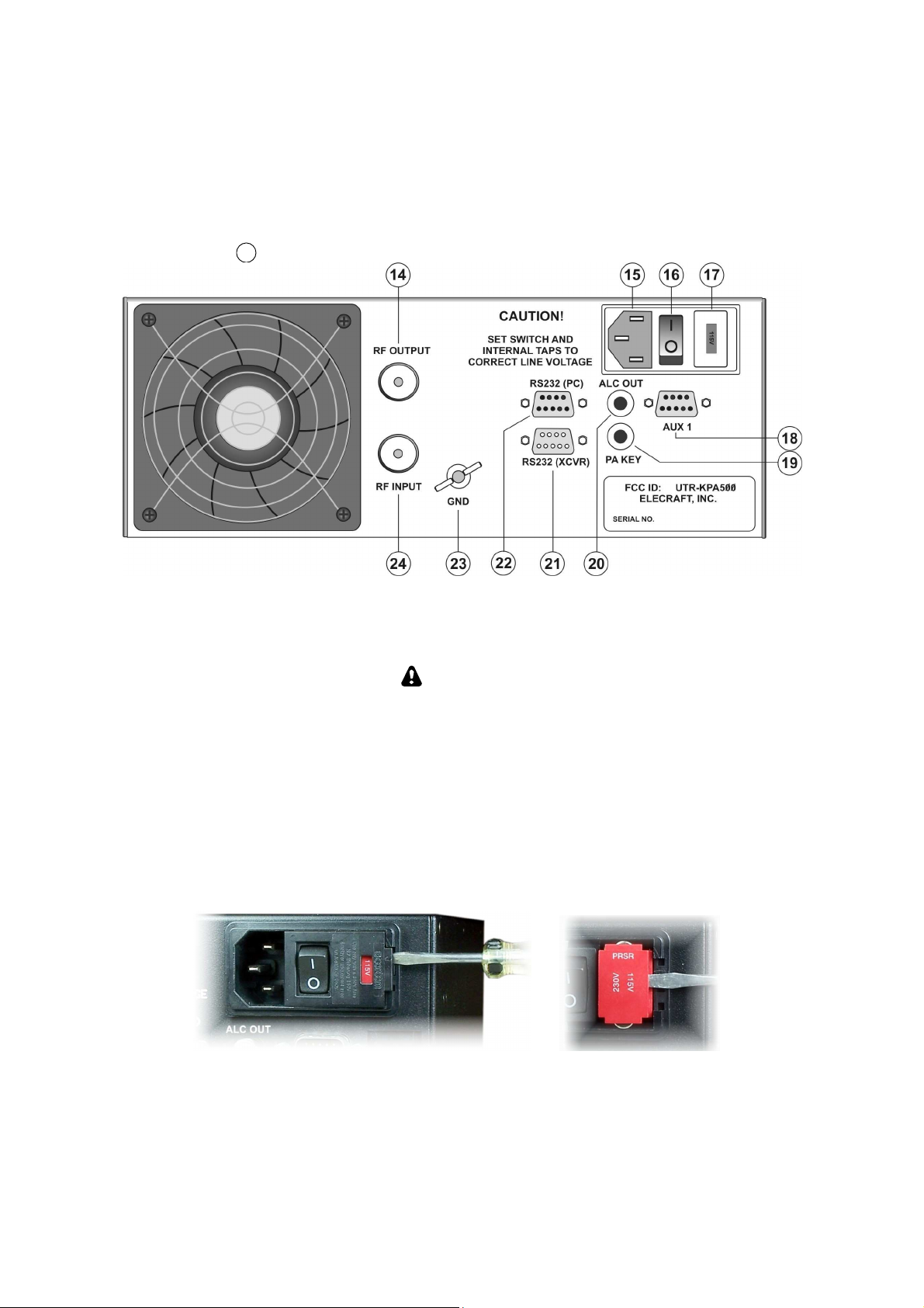
Figure 1. KPA 500 Rear Panel
connector.
Mains Voltage Settings
CAUTION!
Do not connect mains power to your KPA500 or attempt to turn it on before
setting the fuse block switch and internal jumpers to match your supply
voltage as described below; otherwise you may do extensive damage to your
amplifier.
1. Check to ensure the fuse block {4} is set for either 120 VAC or 240 VAC to match your mains voltage.
The current voltage setting is shown in the red window. If needed, change the fuse block setting as
follows:
• Open the door covering the fuse block and then carefully pry the red fuse block out of the holder as
shown below:
• Install the proper fuses in the block. Use 12A fuses for 115V and 6A fuses for 230V.
• Replace the fuse block so that the correct mains voltage appears in the window in the cover.
4
Page 5
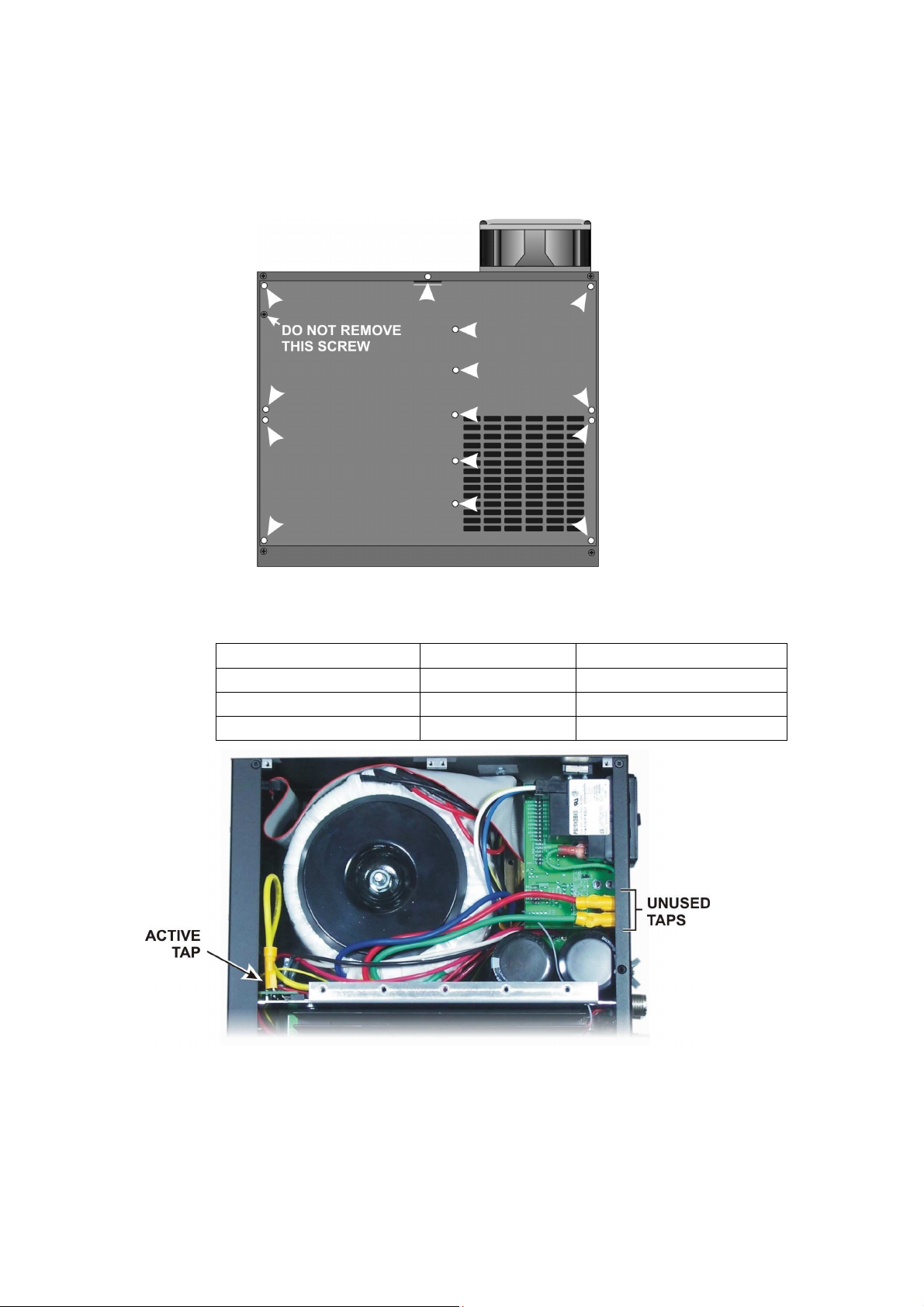
2. Set the internal transformer tap for the specific voltage within the 120 or 240 VAC ranges as follows:
• Remove the 14 screws securing the KPA500 top cover as shown below. Do not remove the screw
indicated. It is part of the safety interlock switch mechanism. Lift the top cover off.
• Three taps are provided via red, green and yellow wires. Choose the tap according to the actual
mains voltage at the outlet you plan to use for the KPA500. If you cannot measure your mains
voltage, use the yellow tap.
115V Nominal Mains TAP 230V Nominal Mains
95V to 105V GREEN 190V to 210V
106V to 115V RED 211V to 230V
115V to 125V YELLOW 231V to 250V
• Be sure to place the unused taps side-by-side on the terminals at the back panel as shown. Do not
leave them floating loose inside the unit.
• Replace the top cover before proceeding. An interlock switch prevents operating the amplifier with
the top cover removed.
5
Page 6

3. Test the power supply voltage output as follows:
• Connect the mains supply cable to {15} on the rear panel and plug the cable into the mains outlet.
(At this point this may be the only cable connected to the rear panel.)
• Position the rear-panel power switch to On (I).
• Tap the front panel ON switch. The LCD should light.
• Tap the HV switch ({3} on Figure 2) and note the voltage displayed on the LCD. It must be between
65 and 80 volts. If it is outside of this range, immediately tap the ON switch to turn the KPA500 off,
and position the rear panel power switch to Off (O). Open the top cover again and select a different
transformer tap. If the voltage was too low, select a tap further up the list in the above table. If the
voltage was too high, select a tap further down the table.
NOTE: If the red FAULT LED lights when you tap the
power supply voltage is above the upper limit. Use a power transformer tap lower on the
above table and retry the test.
Cabling
1. Connect your station ground to the
safety and to minimize local radio frequency interference (RFI).
2. Attach the
RF INPUT
{11} to the output of your driving transceiver or transmitter using a 50 ohm
coaxial cable with an PL-259 male connector on the KPA500 end. The driving transmitter must supply
up to 40 watts for full output from the KPA500.
3. Attach the
RF OUTPUT {1}
to a suitable load with an SWR of less than 1.5:1. A dummy load is strongly
recommended for initial testing.
4.
Connect the PA KEY
{8} to the driving transmitter Key Output. This line must be grounded to transmit,
and 1 mA of current is sourced. The KPA500 PA KEY jack is pulled up to 5VDC when not
transmitting.
5. Optional: If the driving transceiver is an Elecraft K3, connect
K3 using the optional cable. This cable is not required to operate your KPA500. It allows full use of the
control functions on the K3. Note: This is not a common VGA computer cable.
6. Optional:
RS232 (PC)
connects the KPA500 to your personal computer with a standard 9-pin serial
cable. Required for updating the KPA500 firmware.
GND
thumbscrew {10}. A good station ground is important for
ON
switch, that indicates the
AUX1
{5} to the AUX connector on the
7. Optional:
RS232 (XVCR)
connects the KPA500 to a Kenwood transceiver using a standard 9-pin serial
cable.
8. Optional:
ALC OUT
{6} provides level information to control the driving transmitter RF level. The
output is negative-going from -4 VDC to -9VDC.
IMPORTANT: Position the amplifier so there is at least 2 inches (5 cm) clearance behind and
above the amplifier for proper air flow.
6
Page 7

Operation
Power On
1. Ensure a suitable 50 ohm load is attached to the
1, {1}). A dummy load is strongly recommended for initial tests.
2. Enable the power supply by pressing the rear panel rocker switch (Figure 1, {3}) to the On (I)
position.
Switches with a legend above and below the pushbutton have two functions. Tap
(press briefly) to activate the function labeled above a switch. Hold to activate the
function labeled below the switch. In the text, tap functions are shown like this:
TEMP
. An example of a hold function is
RF OUTPUT
IMPORTANT
PK HOLD
connector on the rear panel (Figure
.
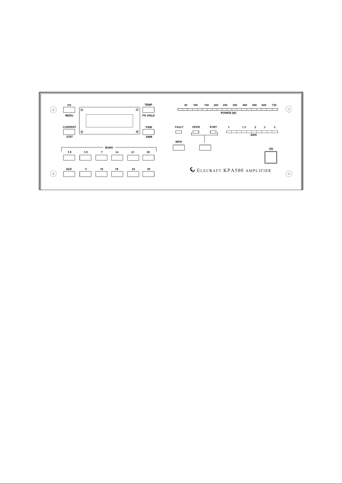
Figure 2. KPA500 Front Panel.
3. Tap the
7
ON switch
NOTE: If at any time the
. The LCD {4} and
STBY
FAULT
LED should light.
LED {7} lights, refer to Fault Conditions, pg. 10.
Page 8

Band Switching
Automatic Band Switching: The KPA500 automatically measures the frequency of the RF drive
and selects the proper band. The
Manual Band Switching: Tap any of the front-panel BAND switches to select that band.
Coordinated Transmitter and KPA500 Band Switching:
• The KPA500 will follow the band selected on a K3 transceiver when the AUX cable is
attached between the KPA500 AUX connector and K3 AUX connector. (pg 6.)
• Tapping a BAND switch on the KPA500 will cause the driving K3 transceiver to change
bands accordingly when the AUX cable is connected.
Important: The automatic band selection function is active whenever PA KEY is low (in transmit
mode) and overrides band selection made by any other means to protect the KPA500 from damage by
wrong-band operation.
Transmitting
PA KEY
input must be connected to the driving transmitter.
1. Tap the OPR/STBY switch {10} and confirm the
2. Apply a few watts of RF drive and note that the
STBY
LED goes out and the
POWER (W)
OPER
LED lights.
LEDs illuminate to indicate the RF
output power.
3. Increase the drive power and confirm that the
indicated by the
SWR
LEDs are green from 1 to 1.5. The 1.5 to 2.1 SWR LEDs are yellow and the LEDs for
POWER (W)
LEDs increases. For ease in reading the critical SWR levels, the
SWR
LEDs indicate less than 1.5 while the output
SWRs above 2.1 are red. Up to 40 watts of drive is required to produce the full 500 watts output
from the KPA500.
Important: Never exceed 40 watts of drive to the KPA500 at any time.
8
Page 9

Monitoring
KPA500 operation is monitored by the LEDs {7}, {8} and {9}and reported in text on the LCD.
LEDs
Standing wave ratio (SWR) of the load and output power are displayed on LED bar graphs. The bar graphs are
color-coded: green for normal operating range, yellow for marginal levels and red for excessive levels.
Excessive levels may trigger a fault and shut the KPA500 off (see Fault Conditions below). A red LED lights if
a fault condition occurs. Also two green LEDs indicate whether the amplifier is in standby (STBY) or operating
(OPER) mode.
LCD
Normally the LCD displays the band currently selected. The four switches around the LCD select other
information to be displayed on the screen and the behavior of the LEDs. Note that these switches have both tap
and hold functions (pg 7). Repeat the tap or hold action to return the LCD to the band display.
• HV {3} displays the PA voltage on the LCD. Must be between 65 and 80 V when the KPA500 is in
standby (STBY) .
•
CURRENT
•
TEMP
•
PWR
•
MENU
{2} displays the PA current on the LCD. Must never exceed 20 A.
{5} displays the heat sink temperature on the LCD. Must be less than 90C.
{6} displays the output power numerically on t he LCD. Must not exceed 650 W
{3} displays the menu system (see pg. 11).
•
EDIT
{2} enables editing menu parameters (see pg. 11).
•
PK HOLD
{5} toggles the peak power output display on the bar graph. When enabled, the LED
corresponding to the peak power output remains lighted for 1 second.
•
SWR
{6} displays the load SWR numerically on the LCD. Must not exceed 2:1.
9
Page 10

Fault Conditions
The
FAULT
switched to standby mode.
indicator {7} lights to indicate a fault condition has occurred and the KPA500 is automatically
Tapping the
INFO
switch displays a text description of the fault condition on the LCD.
Low Level Faults
If the
FAULT
indicator is blinking, one of the following low level faults has occurred and will clear
automatically when the condition is corrected.
Fault Cause/Correction
Over Drive RF Drive > 40 Watts / Reduce RF drive to the KPA500
Over Output Excessive RF Output / Reduce RF Drive to KPA500.
High Reflected Power Reflected Power > 60 Watts
Invalid Frequency Frequency counter detected transmissions in a restricted frequency band. Amp
is automatically bypassed until the counter detects this error has been corrected.
High Level Faults
If the indicator is on steady, one of the following high-level faults has occurred and the KPA500 has
automatically switch to
Fault Cause/Correction
STBY
mode. Clear the fault, then tap the OPR/STBY switch to resume operation.
HV Error Top Cover Interlock Switch Open / Replace and secure KPA500 top cover.
Over Drive RF Drive > 40 Watts over a period of time, or over 60 Watts momentarily. /
Reduce RF drive to the KPA500
Over Temp Power Amp Heat Sink > 90°C / Check to ens ure top and rear air vents clear.
Over Current Excessive Current to Power Amplifier / Check and reduce SWR.
High Reflected Power Reflected power > 60W for an extended period of time or > 100W momentarily.
Open Load Indicated SWR > 18:1
Over Dissipation Finals are dissipating more than 600W of heat
10
Page 11

Menu
Holding
MENU
{3} enables the menu function to allow the following parameters to be set. With the menu
function enabled, the MENU, EDIT and switches next to the and symbols all respond to a simple tap. Use
the and switches to scroll through the menu items. Tap
parameter and tap
Entry Default Description Notes
ALC THR -4 ALC Threshold Adjustment
ATTN REL
FAN CTL NOR Minimum Fan Speed Allows fan to turn off when not
FW REV Displays firmware revision
MENU
again to save the parameter and again to exit the menu.
1
Attenuator Release Time in Seconds/8
EDIT
and the and switches to select the
needed.
LCD ADJ 50 LCD Contrast Adjustment
LCD BRT 6 LCD Backlight Brightness
LED BRT 6 LED Brightness Adjustment
PWR ADJ 100 Wattmeter Calibration By-band calibration factor
RADIO K3 Specifies driving transceiver model
RS232 A 38400 Serial Port A Speed in Baud
RS232 B 38400 Serial Port B Speed in Baud
TR TIME 0 QSK Delay Time Slows T>R release time. For
transceivers with poor transmit
timing characteristics
11
Page 12

Firmware Updates
New features and improvements are available to all KPA500 owners via firmware upgrades.
Please visit the Elecraft K3 software page (www.elecraft.com) to obtain our free firmware download
application, KPA500 Utility. Versions of the Utility program are provided for PCs, Macs, and Linux platforms.
Some applications or peripheral devices may interfere with P3 downloads; check the Help information
in KPA500 Utility if you have difficulty.
If you don’t have Internet access, you can obtain a firmware upgrade on CD. If you don't have a computer, you
can send your P3 to Elecraft to be upgraded. See Customer Service, pg.14.
Checking your Firmware Revision
Use the MENU entry FW Rev to determine your firmware revision.
Updating K3 Firmware
12
Page 13

Specifications
Frequency Range
All Amateur Bands from 1.8 to 29.7 MHz and 50 to 54 MHz
Supply Voltage and
Current
Weight
Size
Power Output
Duty Cycle at 500 Watts
Drive Power
Input VSWR
ALC Out
Metering
100 to 125 VAC or 200 to 250 VAC, 50/60 Hz, approx. 1000 VA
26 lbs
Enclosure only, 4.0 x 10.7 x 10.0 in., HWD (10.2 x 27.2 x 25.4 cm). With projections,
4.4 x 11.1 x 11.8 in. (11.2 x 28.2 x 30.0 cm)
500 watts
10 minutes key down / 5 minutes off
30 to 40 watts for 500 watts output
Less than 1.5:1
Negative-going, adjustable.
Power Output, SWR (bargraph and on the LCD display), supply voltage and current,
temperature, frequency band.
SWR
PA Current
PA Voltage
Heat Sink Temperature
Key In
Efficiency
TBD
20A maximum
60 VDC, nominal
90°C, maximum
+5V open circuit on receive, closed to ground on transmit (1 mA max.)
Approximately 50%
13
Page 14

Customer Service and Support
Technical Assistance
You can send e-mail to k3support@elecraft.com and we will respond quickly – typically the same day
Monday through Friday. If you need replacement parts, send an e-mail to parts@elecraft.com. Telephone
assistance is available from 9 A.M. to 5 P.M. Pacific time (weekdays only) at 831-763-4211. Please use e-mail
rather than calling when possible since this gives us a written record of the details of your problem and allows us
to handle a larger number of requests each day.
Repair / Alignment Service
If necessary, you may return your Elecraft product to us for repair or alignment. (Note: We offer unlimited email
and phone support, so please try that route first as we can usually help you find the problem quickly.)
IMPORTANT: You must contact Elecraft before mailing your product to obtain authorization for the
return, what address to ship it to and current information on repair fees and turn around times. (Frequently we
can determine the cause of your problem and save you the trouble of shipping it back to us.) Our repair location
is different from our factory location in Aptos. We will give you the address to ship your kit to at the time of
repair authorization. Packages shipped to Aptos without authorization will incur an additional shipping charge
for reshipment from Aptos to our repair depot
.
Elecraft 1-Year Limited Warranty
This warranty is effective as of the date of first consumer purchase (or if shipped from the factory, the date the
product is shipped to the customer). It covers both our kits and fully assembled products. For kits, before requesting
warranty service, you should fully complete the assembly, carefully following all instructions in the manual.
Who is covered: This warranty covers the original owner of the Elecraft product as disclosed to Elecraft at the time
of order. Elecraft products transferred by the purchaser to a third party, either by sale, gift, or other method, who is
not disclosed to Elecraft at the time of original order, are not covered by this warranty. If the Elecraft product is being
bought indirectly for a third party, the third party’s name and address must be provided at time of order to ensure
warranty coverage.
What is covered: During the first year after date of purchase, Elecraft will replace defective or missing parts free of
charge (post-paid). We will also correct any malfunction to kits or assembled units caused by defective parts and
materials. Purchaser pays inbound shipping to us for warranty repair; we pay shipping to return the repaired
equipment to you by UPS ground service or equivalent to the continental USA and Canada. For Alaska, Hawaii, and
other destinations outside the U.S. and Canada, actual return shipping cost is paid by the owner.
What is not covered: This warranty does not cover correction of kit assembly errors. It also does not cover
misalignment; repair of damage caused by misuse, negligence, or builder modifications; or any performance
malfunctions involving non-Elecraft accessory equipment. The use of acid-core solder, water-soluble flux solder, or
any corrosive or conductive flux or solvent will void this warranty in its entirety. Also not covered is reimbursement
for loss of use, inconvenience, customer assembly or alignment time, or cost of unauthorized service.
Limitation of incidental or consequential damages: This warranty does not extend to non-Elecraft equipment or
components used in conjunction with our products. Any such repair or replacement is the responsibility of the
customer. Elecraft will not be liable for any special, indirect, incidental or consequential damages, including but not
limited to any loss of business or profits.
14
Page 15

15
Theory of Operation
When the KPA500 is in Operating (OPER) mode, RF is routed by the Transmit-Receive (TR) switch to the
Power Amplifier (PA) module where it is amplified by a pair of VRF2933 FETs.
The PA module output is routed to the Low Pass Filter (LPF) bank input. The LPF bank provides filters for each
frequency band. The frequency of the incoming signal is monitored and the appropriate filter is automatically
switched into the signal path. The filter also may be selected by band data provided by the transceiver or by
front panel switches on the KPA500. However, the automatic selection based on the incoming signal frequency
over-rides either of those inputs to ensure the correct bandpass filter is always in the signal path.
The output of the LPF bank is routed to the RF Output via the TR Switch.
During receive or when the KPA500 is in Standby (STBY), the TR switch routes the RF Input directly to the RF
Output, bypassing both the PA Module and the Low Pass Filter Bank.
The MCU in the Display and Control module monitors and makes critical measurements of a number of
operating conditions including two levels of fault conditions that automatically alter the operation of the
KPA500:
1. If an undesirable, but not critical, fault conditions occurs, a 3 dB attenuator is switched in line with the
PA input and the red FAULT LED is blinked at a 1 Hz rate to alert the operator. An example of such a
fault is overdriving the KPA500 input. When the fault is corrected, such as reducing the driving power,
the 3 dB attenuator is switched out automatically and FAULT light stops blinking.
2. If a critical fault occurs, the amplifier is automatically switched to STANDBY, passing the RF drive
directly through to the RF Output. The red FAULT LED is lighted continuously and the fault
conditions are displayed on the front panel.
Page 16

16
INTERFACE CABLES
Aux Connector
The KPA500 AUX connector has the following pin assignment.
(PINOUT TABLE)
AUX Interface Cable
An optional interface cable is available for Elecraft K3 users. The pin assignments are as follows.
(PINOUT TABLE)
Page 17

17
KIT ASSEMBLY PROCEDURE
TBD
 Loading...