

Page 1
ELECRAFT
HIGH-PERFORMANCE 160 – 6 METER
T
RANSCEIVER
KDVR3 DIGITAL VOICE RECORDER OPTION
NSTALLATION INSTRUCTIONS
I
Rev C, February 16, 2012
Copyright © 2012, Elecraft, Inc.
K3
All Rights Reserved
Page 2

Contents
Introduction ............................................................................................................................................... 3
Customer Service and Support ............................................................................................................................ 3
Technical Assistance ....................................................................................................................................... 3
Repair / Alignment Service ............................................................................................................................. 3
Preventing Electrostatic Discharge Damage ............................................................................................ 4
How ESD Damage Occurs .................................................................................................................................. 4
Preventing ESD Damage ..................................................................................................................................... 4
Preparing for Installation .......................................................................................................................... 5
Tools Required .................................................................................................................................................... 5
Parts Included ...................................................................................................................................................... 5
Installation Procedure ............................................................................................................................... 6
Removing the Front Panel Assembly .................................................................................................................. 6
Removing the DSP Board(s) ............................................................................................................................... 8
Installing the KDVR3 Board ............................................................................................................................... 9
Hardware Upgrades ........................................................................................................................................... 10
Reassembling the K3 ......................................................................................................................................... 11
Preparing the KDVR3 for Operation ...................................................................................................... 13
Using the Digital Voice Recorder ..................................................................................................................... 14
2
Page 3

Introduction
The KDVR3 Digital Voice Recorder allows you to prerecord voice messages to be transmitted and to record
received audio. The KDVR3is contained on a single circuit board that plugs into the main DSP board.
This manual describes how install the KDVR3 in your K3. See Digital Voice Recorder (DVR) in your K3
Owner’s Manual for instructions for using the KDVR3.
Only a few basic hand tools are needed (see page 5) to perform the installation. No soldering or wiring is
required.
Customer Service and Support
Technical Assistance
You can send e-mail to K3support@elecraft.com and we will respond quickly - typically the same day Monday
through Friday. Telephone assistance is available from 9 A.M. to 5 P.M. Pacific time (weekdays only) at 831662-4211. Please use e-mail rather than calling when possible since this gives us a written record of the details
of your problem and allows us to handle a larger number of requests each day
Repair / Alignment Service (We want to make sure everyone succeeds!)
If necessary, you may return your Elecraft product to us for repair or alignment. (Note: We offer unlimited email
and phone support to get your kit running, so please try that route first as we can usually help you find the
problem quickly.)
IMPORTANT: You must contact Elecraft before mailing your product to obtain authorization for the
return, what address to ship it to and current information on repair fees and turnaround times. (Frequently we
can determine the cause of your problem and save you the trouble of shipping it back to us.) Our repair location
is different from our factory location in Aptos. We will give you the address to ship your kit to at the time of
repair authorization. Packages shipped to Aptos without authorization will incur an additional shipping charge
for reshipment from Aptos to our repair depot
.
.
Elecraft's 1-Year Limited Warranty
This warranty is effective as of the date of first consumer purchase (or if shipped from factory, date product is shipped
to customer). It covers both our kits and fully assembled products. For kits, befor e requesting warranty service, you
should fully complete the assembly, carefully following all instructions in the manual.
Who is covered: This warranty covers the original owner of the Elecraft product as disclosed to Elecraft at the time of
order. Elecraft products transferred by the purchaser to a third party, either by sale, gift or other method, who is not
disclosed to Elecraft at the time of original order, are not covered by this warranty. If the Elecraft product is being
bought indirectly for a third party, the third party's name and address must be provided to Elecraft at time of order to
insure warranty coverage.
What is covered: During the first year after date of purchase, Elecraft will replace defective or missing parts free of
charge (post-paid). We will also correct any malfunction to kits or assembled units caused by defective parts and
materials. Purchaser pays inbound shipping to Elecraft for warranty repair, Elecraft will pay shipping to return the
repaired equipment to you by UPS ground service or equivalent to the continental USA and Canada. Alaska, Hawaii
and outside U.S. and Canada actual return shipping cost paid by owner.
What is not covered: This warranty does not cover correction of kit assembly errors. It also does not cover
misalignment; repair of damage caused by misuse, negligence, or builder modifications; or any performance
malfunctions involving non-Elecraft accessory equipment. The use of acid-core solder, water-soluble flux solder, or any
corrosive or conductive flux or solvent will void this warranty in its entirety. Also not covered is reimbursement for loss
of use, inconvenience, customer assembly or alignment time, or cost of unauthorized service.
Limitation of incidental or consequential damages: This warranty does not extend to non-Elecraft equipment or
components used in conjunction with our products. Any such repair or replacement is the responsibility of the customer.
Elecraft will not be liable for any special, indirect, incidental or consequential damages, includ ing but not limited to any
loss of business or profits.
3
Page 4

Preventing Electrostatic Discharge Damage
There is no climate or work location where the components of your K3 are safe from Electrostatic Discharge
(ESD) unless you take specific steps to prevent such damage. Many of the components in your K3 can be
damaged by static discharges of only a few volts: far too little for you to notice. It is those low-voltage but
destructive discharges that easily happen anywhere and under virtually any environmental conditions.
ESD damage may not be apparent at first. The damaged components may not fail completely. Instead, the
damage may result in below-normal performance for an extended period of time before you experience a total
failure.
How ESD Damage Occurs
Whenever an object containing a static charge touches a circuit in your K3, current will rush into the circuit until
the components reach the same voltage as the source of the static charge. If the voltage or current that passes
through a component during that brief period exceeds its normal operating specifications, it may be damaged or
destroyed.
Preventing ESD Damage
ESD damage cannot occur if there is no voltage difference between the components in your K3 and any object
that touches them. That is how anti-static packaging works. Anti-static bags allow the static charge to flow over
their surface, so that any part of the bag that touches the components inside are all at the same potential at all
times. Anti-static foam keeps the leads of sensitive components at the same potential.
At your work bench, avoiding a dangerous voltage is achieved most easily by tying everything together and
connecting them to a common mains safety ground. This includes your K3, individual boards or other sensitive
components as well as everything they may touch at the work table.
Inexpensive static dissipating work mats are readily-available that will steadily and safely drain off any charges
built up on parts or circuit boards placed on them. They are supplied with a lead that connects the mat to the
common workbench ground. Also, metal cabinets on test equipment used on the bench should be tied together
and connected to the common ground.
Most importantly, you must have a way of continuously draining off any static charges that occur on your body.
Such charges are easy to create, even while sitting quietly at the work bench. Moving your feet on the floor,
shifting position in your chair or even moving your arms so that clothing rubs against itself can produce
destructive static charges. You can discharge yourself by touching an unpainted metal ground, but that will last
only until you move in a way that produces a new static charge. The safest technique is to wear a grounded wrist
strap with a series 1-megohm resistor that continuously drains off any charges. Such wrist straps are readilyavailable and inexpensive.
WARNING
DO NOT attach a ground directly to yourself without a current-limiting resistor as this poses
a serious shock hazard. A wrist strap must include a 1-megohm resistor to limit the current
flow. If you choose to touch an unpainted, metal ground to discharge yourself, do it only
when you are not touching any live circuits with your other hand or any part of your body.
We strongly recommend you take the following anti-static precautions (listed in order of importance) to avoid
trouble:
Leave ESD-sensitive parts in their anti-static packaging until you install them. The packaging may be a
special plastic bag or the component’s leads may be inserted in conductive foam. Parts which are
especially ESD-sensitive are identified in the parts list and in the assembly procedures.
4
Page 5
Wear a conductive wrist strap with a series 1-megohm resistor. If you do not have a wrist strap, touch a
ground briefly before touching any sensitive parts to discharge your body. Do this frequently while you
are working. You can collect a destructive static charge on your body just sitting at the work bench. DO
NOT attach a ground directly to yourself as this poses a serious shock hazard.
Use a grounded anti-static mat on your work bench.
If you choose to use a soldering iron to work on your K3 for any reason, be sure your iron has an ESD-
safe grounded tip tied to the same common ground used by your mat or wrist strap.
Preparing for Installation
Tools Required
1. #0 and #1 size Phillips screwdrivers. To avoid damaging screws and nuts, a power screwdriver is not
recommended. Use the screwdriver that best fits the screw in each step.
2. Blade screwdriver to fit the pry slots when removing the front panel assembly (see Figure 6 on page 8).
3. Pliers for installing 1/4” (6.4mm) nuts and standoffs
4. Small diagonal cutters.
5. Soft cloth or clean, soft static dissipating pad to lay cabinet panels on to avoid scratching.
The following tools are strongly recommended:
1. ESD wrist strap.
2. Static dissipating work pad.
Parts Included
The following parts should be included in your kit. Check to ensure you have them all. If any parts are damaged
or missing, contact Elecraft for replacements (see Customer Service and Support, page 3).
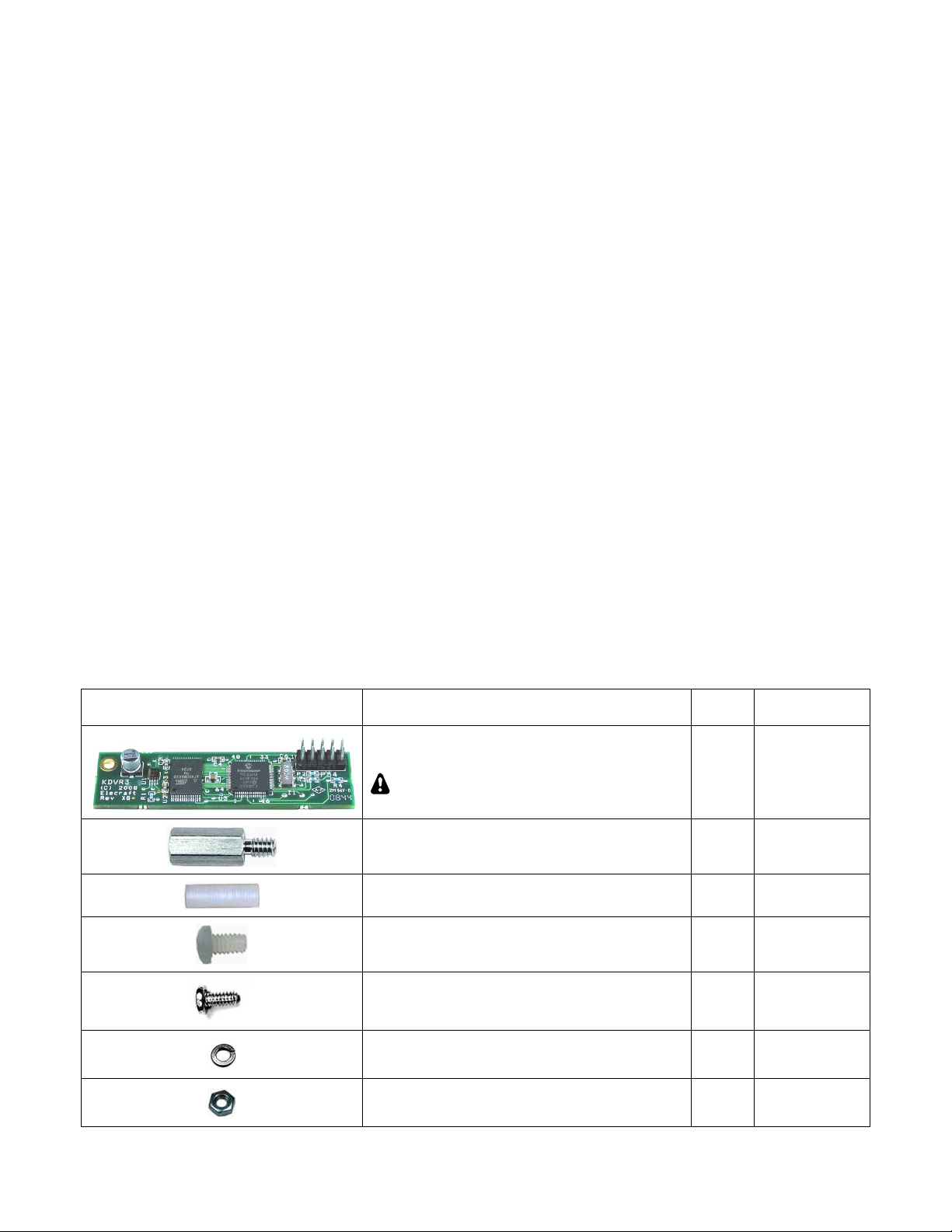
ILLUSTRATION DESCRIPTION QTY.
KDVR3 Printed Circuit Board Assembly
ESD Sensitive.
Standoff, Hex Male/Female, 7/16” (11mm) 1 E700017
Standoff, Nylon, 5/8” (15.9 mm) 1 E700163
Screw, Nylon, Pan Head 4-40, 1/4” (6.8 mm) 3 E700166
Screw, Zinc, Pan Head 4-40 1/4” (6.8mm) 1 E700005
Lock Washer, 4-40, Split 3 E700004
1 E850246
ELECRAFT
PART NO.
Nut, 4-40 1 E700011
5
Page 6

Installation Procedure
Removing the Front Panel Assembly
Disconnect power and all cables from your K3.
Remove the nine screws to free the top cover as shown in Figure 1. After the cover is open, lift it gently to
reach the speaker wire connector. Unplug the speaker then set the top cover aside in a safe place.
Whenever you remove screws from a panel, if one screw seems too tight to loosen
without damaging it, first loosen the other screws then try again. Sometimes one screw
binds in its hole when the other screws are tightened.
Figure 1. Removing K3 Top Cover.
CAUTION:
before touching components or circuit boards inside the K3. See Preventing ESD Damage on
page 4 for more information.
Stand the K3 on its side feet, remove the seven screws shown in Figure 2 and lift the left side panel off. Set
the side panel aside in a safe place to avoid scratches.
Touch an unpainted metal ground or wear a grounded wrist strap
Figure 2. Removing the Left Side Panel.
6
Page 7

Remove the screw shown in Figure 3. It is located directly behind the front panel microphone connector.
There may be a lock washer under the screw. If so, save it with the screw. Removing the screw ensures the pc
boards on the front panel assembly will have adequate clearance when the front panel assembly is removed in a
later step. Remove only the screw shown. Leave the other screw in place as shown in the figure.
Figure 3. Removing the 2D Screw.
Remove the three screws securing the top of the front panel assembly as shown in Figure 4.
Figure 4. Removing the Top Front Panel Screws.
Turn the K3 upside down. Place it on a clean, soft surface to avoid scratching the top of the front or rear
panels.
it in a safe place to avoid scratches.
Refer to Figure 5 and remove screws 1 through 7, then lift the forward section of the bottom cover off. Put
Figure 5. Removing Bottom Cover and Front Panel Assembly Screws.
Refer to Figure 5 and remove screws 8 and 9 that secure the bottom of the front panel assembly.
7
Page 8

CAUTION:
three top Front Panel Assembly screws shown in Figure 4. You may bend and damage the
front panel or shield assemblies if the screws are not removed!
Use a screwdriver in the pry tool openings to press back against the circuit board while pushing the lip on
the front panel assembly toward the front as shown in Figure 6. Do not insert the screwdriver any farther
than necessary to avoid damaging components! When you have the front panel assembly free, set the main
chassis aside in a safe place.
Before continuing on with the next step, be sure you have removed the
Figure 6. Separating the Front Panel Assembly from the Chassis.
Removing the DSP Board(s)
On the front panel, remove the knurled nut
from the PHONES jack directly above the MIC
connector (see Figure 7). Be very careful not to
scratch the paint on the front panel.
Place the front panel assembly face down on a
smooth, clean soft surface to avoid scratches to the
LCD cover or front panel paint
Remove the three screws and split lock washers shown in Figure 8.
Figure 7. Phones Jack Knurled Nut.
Figure 8. Removing DSP Board Assembly.
8
Page 9

With the three screws removed, the main DSP board is held on to the front panel board by two multi-pin
connectors. Slip your finger tips between the boards and pull the main DSP board away from the front panel
board to unplug it.
A large, thick spacer washer should be lying on
the front panel near the hole for the phones jack
(see Figure 9). This spacer fits between the phones
jack and the back of the front panel board to
provide a solid mechanical ground connection when
the boards are in place. Remove the washer and set
it aside. If it’s lying on the inside of the front panel
you can tip the panel so it will slide out at the end.
Figure 9. Phones Jack Washer
Installing the KDVR3 Board
Install the KDVR 3 board on the main DSP board as shown in Figure 10. Be sure you use the nylon screw.
A metal screw here may short to the front panel board after reassembly. Do not over tighten the nylon screw. It
is easy to strip the threads. Look at the split in the lock washer and tighten the screw only until the washer is
compressed flat.
Figure 10. Installing the KDVR3 Board on the Main DSP Board.
9
Page 10

Hardware Upgrades
The following changes have been implemented in newer K3s to avoid the possibility of shorts or intermittent
operation in some K3s. All the hardware needed is supplied with your KDVR3 kit.
If you have the KRX3 installed, check the three screws securing the auxiliary DSP board to the main DSP
board to see if they are nylon or metal (see Figure 11). A nylon screw was originally used in one location. If the
other two are metal, replace them with the 4-40, 1/4” (6.4mm) nylon screws supplied. Use the same metal split
lock washers under each screw. This change eliminates the possibility of one of the metal screw heads shorting
to a live circuit on the front panel board.
Figure 11. Aux DSP Board Screws.
Check to see if the nylon standoff shown below near J51 is mounted on the main DSP board (see Figure
12). If not, install the nylon standoff supplied with your KDVR3 parts as shown. Be sure you place it in the
correct hole near the corner of the board. This standoff ensures that the main DSP board does not flex when the
front panel assembly is mounted on the chassis.
CAUTION: To avoid damaging a circuit trace very close to the metal ring around the screw hole, position the
lock washer under the screw so the split faces away from the trace. Tighten the hardware by turning the standoff
while holding the screw and lock washer stationary. Do not over-tighten the screw. It is easy to strip the
threads in the nylon standoff.
Figure 12. Installing Nylon Standoff on Main DSP Board.
10
Page 11

Check the VFO B encoder and trim the pins as shown below if they haven’t been trimmed already to ensure
they cannot short against the main DSP board. If trimming is needed, remove the encoder to ensure clipped ends
don’t get lost in the front panel assembly. To remove the encoder, loosen the set screws and remove the knob,
then remove the felt washer and nut and lift the encoder out. You need trim only the five pins shown close to the
back of the pc board. Replace the encoder by reversing the process. Be sure the spacer nut on the inside is tight
against the shoulder of the ferrule.
Figure 13. Checking and Trimming the VFO B Encoder Pins.
Reassembling the K3
Mount the DSP board assembly on the front panel board as follows.
Place the front panel assembly face down on a soft, clean surface to protect the finish. The back
side of the front panel board should be facing upward.
Position the large flat washer on the inside of the front panel over the PHONES jack hole (see
Figure 9 on page 9). This is easily done by sliding the washer into place from the end of the
front panel.
Gently position the DSP board assembly on the front panel board so that the large jack fits
through the cutout in the front panel board with the threaded section passing through the large
flat washer and the circular opening in the front panel. Adjust the position of the board as
needed so you can see the standoffs on the front panel board lined up with the screw holes in the
main DSP board. Note: The nylon standoff next to J51 rests against the front panel board, but is
not attached to it.
Pick up the assembly while holding the DSP assembly board in place and inspect the position of
the two male plugs on the DSP board. They should mate with J31 and J32 on the front panel
board. J31 is near the encoder for VFO A and J32 is between the two dual potentiometers.
Adjust the DSP board’s position as needed so the pins enter the corresponding holes in the
sockets on the front panel board.
Squeeze the boards together while ensuring the pins are mating with the connectors until the
DSP board is resting against the three standoffs on the back of the front panel board that you
installed earlier. The two connectors will not mate completely. About 1/4” (6.4mm) of the pins
may be visible when the DSP board is positioned against the standoffs.
Replace the three 4-40 1/4” (6.4 mm) zinc pan head screws you removed earlier with a split lock washer
under each screw head (see Figure 8 on page 8).
Replace the knurled nut on the PHONES jack (see Figure 7 on page 8).
11
Page 12

Turn the chassis upside down and position the front panel so the pins of P30 and P35 on the bottom of the
RF board just begin to engage the connectors on the lower edge of the front panel assembly as shown in Figure
14). Do not fully mate them yet.
Figure 14. Mounting the Front Panel Assembly- Mating P30 and P35.
Hold the front panel in place against the chassis assembly and turn the unit over to look at the two multipin connectors on the top of the RF board. See if they are engaging the corresponding connectors on the front
panel assembly (see Figure 15). Adjust the position of the RF board or the front panel assembly to ensure they
are mating properly.
Figure 15. Mounting Front Panel Assembly - Mating P50 and P51.
With the pins of all four connectors started, press the front panel onto the RF board connectors. Press only
from the bottom of the front panel to avoid flexing the RF board. You can use your fingers to press on the back
side of each multi-pin connector on the top of the RF board while holding the front panel to engage them. There
may be small areas of pins showing even after they are mated. You will know they are properly mated when the
screw holes on the bottom lip of the front panel assembly line up with the screw holes in the 2D fasteners on the
bottom of the RF board.
Secure the front panel assembly at the bottom lip to the 2D fasteners at the forward edge of the RF board
with the two 4-40 3/16” (4.8 mm) black pan head screws you removed earlier. No lock washers are used on the
external case screws.
Fasten the top of the front panel assembly with three 4-40 3/16” (4.8 mm) black flat head screws (see
Figure 4).
Replace the 3/16” (4.8 mm) black pan head screw and, if used, lock washer in the 2D fastener (see Figure 3
on page 7).
12
Page 13

Replace the left side panel (with the handle) as follows:
Start the seven 4-40 3/16” (4.8 mm) black flat head screws through the panel: three along the bottom,
one at the top rear, one at the top front, and one just below the front end of the handle. It is normal to
adjust the position of the panels slightly when assembling so the screw holes line up. The cabinet will
become structurally sound and rigid when all the panels, including the top and bottom covers, are
mounted.
Tighten all seven screws. Be sure all the screws are tight, including the screw near the forward end of
the handle that threads into the front panel shield.
Replace the forward bottom cover using seven 3/16” (4.8 mm) black pan head screws (see Figure 5 on
page 7).
Hold the top cover above the K3, route the speaker wire under the stiffener bar and plug it into P25 on the
KIO3 board at the left rear of the K3 as shown in Figure 16.
Figure 16. Connecting Speaker Cable.
Replace the nine top cover screws shown in Figure 1on page 6. Replace and tighten all the screws. Loose or
missing screws may result in birdies or other hard-to-locate problems with your K3.
Preparing the KDVR3 for Operation
Enable the K3DVR module as described in your K3 Owner’s Manual under Option Module Enables.
Your KDVR3 will not operate until you have enabled it as described in the step above.
That completes the installation of your KDVR3 digital voice recorder. Detailed instructions for using your
digital voice recorder are on the following page.
13
Page 14

Using the Digital Voice Recorder
Note: You must have MCU firmware version 2.73
or later installed.
The KDVR3 option allows you to record and play
voice messages as well as capture received audio.
Transmit Message Record and Playback
MIC gain must be set to show 5 bars on the
ALC display on voice peaks for the proper
recording level.
You cannot transmit and record at the same time:
Using PTT: You do not need to press the PTT
unless that is required for your mic to produce
audio. In that case, press the PTT after starting
record or you will transmit, not record. Once
recording starts, you will not transmit even if you
are still holding the PTT closed at the end of the
recording time period.
Using VOX: Either disable VOX while recording or
take care not to trip the VOX until after starting
record or you will transmit, not record. Stop
speaking at the end of the recording period to avoid
accidentally transmitting.
Hold AF PLA Y to start play. The
icon will
flash quickly. A seconds counter will be displayed
on VFO B, along with an asterisk (*) if you’re
within the most recently recorded audio segment.
Rotating VFO B jumps forwards/backwards
through recorded audio. To stop play, tap any
button.
To transmit recorded audio, press the PTT or tap
XMIT. If you tap the XMIT button, do so before
starting playback since tapping any button stops
playback.
IMPORTANT NOTES:
1. Messages may be at least 10 seconds long.
2. The recorder takes the audio after the MIC
gain control but before it is filtered and
processed. Compression and equalization
may be applied to playback audio.
To start recording, tap
M4 . The remaining buffer time in seconds will be
REC then tap any of M1 -
displayed as you speak. Tap REC again to stop.
Hold REC to select bank 1 or 2 (4 messages each).
Tap M1 – M4 to play. To cancel, tap REC .
To auto-repeat a message, hold (rather than tap) M1
– M4 . MAIN: MSG RPT sets the message repeat
interval (1 to 255 seconds).
To play back two memories in a continuous chain,
hold the memory button for the first message until
REPEAT appears, then tap the memory button for
the second message. CHAIN will appear briefly.
The second message will start automatically after
the first message ends.
Receive Audio Record and Playback
Hold AF REC to start record. The
icon will
flash slowly. To stop recording, hold AF REC
again. The most recent 90 seconds of recorded
audio will be available for playback.
14
 Loading...