

Page 1
ELECRAFT
KAT500 AUTOMATIC ANTENNA
TUNER
OWNER’S MANUAL
Revision A, November 1, 2012
Copyright © 2012, Elecraft, Inc.
All Rights Reserved
Page 2

Contents
Introduction ............................................................................................................................................... 3
Quick Start ................................................................................................................................................ 3
Customer Service and Support ................................................................................................................. 3
Technical Assistance ....................................................................................................................................... 3
Repair / Alignment Service ............................................................................................................................. 3
Specifications ............................................................................................................................................ 4
Setup ......................................................................................................................................................... 5
Cabling ................................................................................................................................................................ 5
Elecraft K3 Transceiver and KPA500 Amplifier using DB15 Interface Cables. ............................................ 5
Elecraft K3 Transceiver and KPA500 Amplifier with Separate Key Line ..................................................... 7
General Cabling Requirements ....................................................................................................................... 9
Interface Cable Wiring ...................................................................................................................................... 10
DB15 Interface Cable .................................................................................................................................... 10
Icom AH-4 Interface ..................................................................................................................................... 10
Operation ................................................................................................................................................ 11
Tuning ............................................................................................................................................................... 11
Fine Tuning ................................................................................................................................................... 12
Cancel Tuning ............................................................................................................................................... 12
Alternate Tuning Commands ........................................................................................................................ 12
Bandswitching ................................................................................................................................................... 13
Turning the KAT500 Off .................................................................................................................................. 13
Fault Conditions ................................................................................................................................................ 13
Utility Program ....................................................................................................................................... 14
KAT500 Configuration ..................................................................................................................................... 14
Antennas ........................................................................................................................................................ 14
Thresholds ..................................................................................................................................................... 14
Memories....................................................................................................................................................... 14
Saving Configuration .................................................................................................................................... 14
Parameter Initialization (EEINIT) ..................................................................................................................... 15
Updating Firmware ........................................................................................................................................... 15
i
Elecraft manuals with color images may be downloaded from
www.elecraft.com
2
.
Page 3

Introduction
The KAT500 Automatic Antenna Tuner is designed to be closely integrated with the Elecraft K3
transceiver and the Elecraft KPA500 amplifier although it may be easily used with other transceivers and
amplifiers. Features include:
Automatic band switching, covering the spectrum from 1.8 through 54 MHz.
Automatic antenna switching to connect one of three antennas according to the band selected.
L and C settings for lowest SWR are stored in memory for extremely rapid frequency and band
changes.
Robust self-protection circuits that guard against damage from switching high-power RF or trying
to match loads outside of its tuning range.
Static bleed resistor built in to avoid damage from normal static buildup on antennas.
Low profile enclosure that matches the footprint of the KPA500 and K3, allowing the KAT500 to
be placed on top or under either unit (the KAT500 is designed to support the weight of the
KPA500).
Quick Start
To quickly set up and get started with your KAT500 Automatic Antenna Tuner, turn to page 5 to hook up
the unit and page 10 for operating instructions.
Customer Service and Support
Technical Assistance
You can send e-mail to k3support@elecraft.com
Monday through Friday. Telephone assistance is available from 9 A.M. to 5 P.M. Pacific time (weekdays
only) at
831-763-4211. Please use e-mail rather than calling when possible since this gives us a written record of
the details of your problem and allows us to handle a larger number of requests each day.
Repair / Alignment Service (We want to make sure everyone succeeds!)
If necessary, you may return your Elecraft product to us for repair or alignment. (Note: We offer
unlimited email and phone support to get your kit running, so please try that route first as we can usually
help you find the problem quickly.)
IMPORTANT: You must contact Elecraft before mailing your product to obtain authorization for the
return, what address to ship it to and current information on repair fees and turnaround times. (Frequently
we can determine the cause of your problem and save you the trouble of shipping it back to us.) Our
repair location is different from our factory location in Aptos. We will give you the address to ship your
kit to at the time of repair authorization. Packages shipped to Aptos without authorization will incur an
additional shipping charge for reshipment from Aptos to our repair depot
and we will respond quickly - typically the same day
.
3
Page 4

Elecraft's 1-Year Limited Warranty
This warranty is effective as of the date of first consumer purchase (or if shipped from factory, date product is
shipped to customer). It covers both our kits and fully assembled products. For kits, before requesting warranty
service, you should fully complete the assembly, carefully following all instructions in the manual.
Who is covered: This warranty covers the original owner of the Elecraft product as disclosed to Elecraft at the
time of order. Elecraft products transferred by the purchaser to a third party, either by sale, gift or other method,
who is not disclosed to Elecraft at the time of original order, are not covered by this warranty. If the Elecraft
product is being bought indirectly for a third party, the third party's name and address must be provided to
Elecraft at time of order to insure warranty coverage.
What is covered: During the first year after date of purchase, Elecraft will replace defective or missing parts
free of charge (post-paid). We will also correct any malfunction to kits or assembled units caused by defective
parts and materials. Purchaser pays inbound shipping to Elecraft for warranty repair, Elecraft will pay shipping
to return the repaired equipment to you by UPS ground service or equivalent to the continental USA and Canada.
Alaska, Hawaii and outside U.S. and Canada actual return shipping cost paid by owner.
What is not covered: This warranty does not cover correction of kit assembly errors. It also does not cover
misalignment; repair of damage caused by misuse, negligence, or builder modifications; or any performance
malfunctions involving non-Elecraft accessory equipment. The use of acid-core solder, water-soluble flux solder,
or any corrosive or conductive flux or solvent will void this warranty in its entirety. Also not covered is
reimbursement for loss of use, inconvenience, customer assembly or alignment time, or cost of unauthorized
service.
Limitation of incidental or consequential damages: This warranty does not extend to non-Elecraft equipment
or components used in conjunction with our products. Any such repair or replacement is the responsibility of the
customer. Elecraft will not be liable for any special, indirect, incidental or consequential damages, including but
not limited to any loss of business or profits.
Specifications
Frequency Range
Supply Voltage and
Current
Weight
Size
Typical Matching
Range and Power
Limits
Autotune Power Range
1.8 to 54 MHz, continuous.
11 to 15 VDC, 1.5A max (200 mA typical).
4.6 lbs (2.1 kg).
Enclosure only, 1.5 x 10.8 x 10.0 in., HWD (3.8 x 27.4 x 25.4 cm). With projections, 1.75
x 10.8 x 11.8 in. (4.4 x 28.4 x 30.0 cm). The projections are the bottom feet and the cable
connectors on the rear.
3 — 30 MHz 600W into 5 Ω to 500 Ω (10:1 SWR).
1000W into 16 Ω to 150 Ω (3:1 SWR).
1.8 — 2 MHz 600W into 10 Ω to 500 Ω (5:1 Low Impedance, 10:1 High Impedance
SWR).
30 — 60 MHz 1000W into 16 Ω to 150 Ω (3:1 SWR).
500W into 5:1 SWR (10 Ω to 250 Ω).
Matching specified to a 1.0:1 to 1.6:1 output SWR. Power rating is ICAS (Intermittent
Commercial and Amateur Service).
10W —100W.
For better matching accuracy, tune with >20W.
4
Page 5

Setup
NOTE: Although the KAT500 works equally well with either a transceiver or a
stand-alone transmitter, transceiver is used throughout this manual for simplicity.
The KAT500 can be used with any 1.8 through 54 MHz transceiver in the 20 to 1000 watt output range,
although the KAT500 integrates most closely with the Elecraft K3 transceiver and the KPA500 amplifier.
The KAT500 may be placed under or above either the Elecraft K3 transceiver or the KPA500 solid state
amplifier. The KAT500 can easily handle the weight of the KPA500 amplifier. The KPA500’s footprint
matches both units and the feet provide adequate spacing for proper cooling of the K3 or KPA500.
Cabling
When using the KAT500 with non-Elecraft equipment, refer to General Cabling
Requirements on page 9.
Diagrams are provided below for stations using the Elecraft K3 and KPA500.
Elecraft K3 Transceiver and KPA500 Amplifier using DB15 interface cables.
Elecraft K3 Transceiver and KPA500 Amplifier with a separate Key line that can be used to
control external equipment (e.g. a Stepper-IR antenna controller).
Elecraft K3 Transceiver and KPA500 Amplifier using DB15 Interface Cables.
Refer to Figure 1(page 6) and the following notes:
50-ohm coaxial RF cables with PL-259 connectors. When using a transceiver with multiple
antenna outputs such as the K3, be sure the correct antenna connection is selected. The KAT500
allows up to three antenna connections, selected from the front panel (See Operation, pg 10).
Two wire power cable with a female 2.1 mm coaxial connector (supplied). Connect to the station
11 to 15 VDC power supply with the white striped lead to the positive terminal. Do not take this
power from the K3’s 12 VDC output connector, even if it has been upgraded for 1 Ampere.
DB15 interface cables with male and female connectors (one cable supplied). Do not use
common VGA cables; they are not wired correctly for this use (See Interface Cable Wiring on page
10). One cable is supplied with the KAT500. If you need a second cable, you can order E850463 from
Elecraft or you can make your own. These cables provide the best integration of the KAT500 with the
K3 and KPA500 by:
Including the essential Key line that inhibits the KPA500 amplifier. The Key line circuit
passes through the KAT500 where it is automatically opened whenever a KAT500 tune
operation occurs. This inhibits the KPA500 to avoid applying excessive RF power while the
KAT500 is tuning. If you need access to the key line to control external equipment, see
Elecraft K3 Transceiver and KPA500 Amplifier with Separate Key Line on page 7.
Providing band data from the K3 to the KAT500 that allows it to switch to the current band at
the same time as the K3 instead of waiting until RF is applied and allows the KPA500
amplifier to send the K3 status information (see the KPA500 Owner’s Manual for complete
details).
5
Page 6

Computer interface cable with a 3.5 mm T-R-S connector at one end and USB connector at the
other end supplied with the KAT500 (supplied). Not required for normal operation, but used for
controlling the KAT500 from a personal computer, customizing the KAT500’s operation or for
updating firmware (see Utility Program on page 14).
Figure 1. Cabling Diagram: Elecraft K3, KPA500 and KAT500 Using DB15 Interface Cables.
6
Page 7

Elecraft K3 Transceiver and KPA500 Amplifier with Separate Key Line
Refer to Figure 2 (page 8) and the following notes:
50-ohm coaxial RF cables with PL-259 connectors. When using a transceiver with multiple
antenna outputs such as the K3, be sure the correct antenna connection is selected. The KAT500
allows up to three antenna connections, selected from the front panel (See Operation, pg 10).
Two wire power cable with a female 2.1 mm coaxial connector (supplied). Connect to the station
11 to 15 VDC power supply with the white striped lead to the positive terminal. Do not take this
power from the K3’s 12 VDC output connector, even if it has been upgraded for 1 Ampere.
Power Amplifier Key cables with RCA connectors (one cable supplied). These cables inhibit the
amplifier to avoid applying excessive RF power while the KAT500 is tuning. You may add other
equipment that requires the amplifier be inhibited in series with this circuit at any point. The circuit
inside the KPA500 is a simple relay closure, so it does not matter which connector goes into each
jack.
DB15 interface cables with male and female connectors (one cable supplied). Do not use
common VGA cables; they are not wired correctly for this use. These cables are optional since a
separate PA Key line is used, but they provide band data from the K3 to both the KAT500 and
KPA500, allowing them to switch bands instead of waiting the them to sense the frequency and
switch bands when RF power is applied.
IMPORTANT:
The key line in the DB15 interface cable must be opened so that external equipment
inserted in the key line can inhibit the amplifier when needed. If you need a second
cable, order the KPAK3AUX Elecraft cable set which includes the key line
interrupter. If you make your own cable you can leave pin 10 at the connectors open
(see Interface Cable Wiring on page 10).
Computer interface cable with a T-R-S connector at one end and USB connector at the other end
supplied with the KAT500. Not required for normal operation, but used for controlling the KAT500
from a personal computer, customizing the KAT500’s operation or for updating firmware (see Utility
Program on page 14).
7
Page 8

Figure 2. Cabling Diagram: Elecraft K3, KPA500 and KAT500 Using DB15 Interface Cables with
Separate Key Line.
8
Page 9

General Cabling Requirements
The KAT500 works well with equipment other than the Elecraft K3 transceiver and KPA500 amplifier.
Figure 3 shows the basic cabling required to work with any transceiver or transceiver and amplifier
combination. See notes below for details about each cable.
Figure 3. General Cabling Requirements.
50-ohm coaxial RF cables with PL-259 connectors. When using a transceiver with multiple
antenna outputs such as the K3, be sure the correct antenna connection is selected. The KAT500
allows up to three antenna connections, selected from the front panel (See Operation, pg 10).
Two wire power cable with a female 2.1 mm coaxial connector (supplied). Connect to the station
11 to 15 VDC power supply with the white striped lead to the positive terminal.
Power Amplifier Key cables with RCA connectors (one cable supplied). These cables inhibit the
amplifier to avoid applying excessive RF power while the KAT500 is tuning. You may add other
equipment that requires the amplifier be inhibited in series with this circuit at any point. The circuit
inside the KPA500 is a simple relay closure, so it does not matter which connector goes into each
jack.
Optional user-supplied cable with a 3.5 mm T-R-S jack that allows Icom transceivers using the
AH-4 protocol to control the KAT500 via a user-supplied cable.
Computer interface cable with a T-R-S connector at one end and USB connector at the other end
supplied with the KAT500 (supplied). Not required for normal operation, but used for controlling the
KAT500 from a personal computer, customizing the KAT500’s operation or for updating firmware
(see Utility Program on page 14).
9
Page 10

Interface Cable Wiring
DB15 Interface Cable
The DB15 Interface cable may be ordered from Elecraft (order E850463). Optionally, you can construct
your own cable using male and female DB-15 connectors wired as follows.
CONNECTOR PINS SIGNAL
2 2 AUXBUS
3 3 BAND 1
5 5 GND
9 9 BAND 2
10 10 PTT (See Note)
11 11 Inhibit
12 12 GND
13 13 BAND0
14 14 BAND3
15 15 ALC (Normally not used. See your KPA500 Owner’s Manual)
NOTE: If you have devices that need access to the PA Key line (e.g. SteppIR controllers, etc.),
leave pin 10 open and use the external key line cable (see Figure 2, cable
KPAK3AUX cable set which includes the DB15 Interface Cable, a key line interrupter is provided
that plugs in between the cable and the K3 to interrupt the pin 10 circuit without modifying your
cable.
. If you purchased the
Icom AH-4 Interface
This cable uses a 4-pin Icom Molex connector at one end and a 2.1 mm coaxial power connector and a
3.5mm T-R-S plug at the other end. The cable is wired as follows:
MOLEX CONNECTOR SIGNAL T-R-S CONNECTOR POWER CONNECTOR
Pin 1 Key Tip NC
Pin 2 Start Ring NC
Pin 3 +12 VDC NC Center
Pin 4 Ground Shield Outer Shell
NOTES: Pin 1 is at the triangular end of the Molex connector. NC = No connection.
10
Page 11

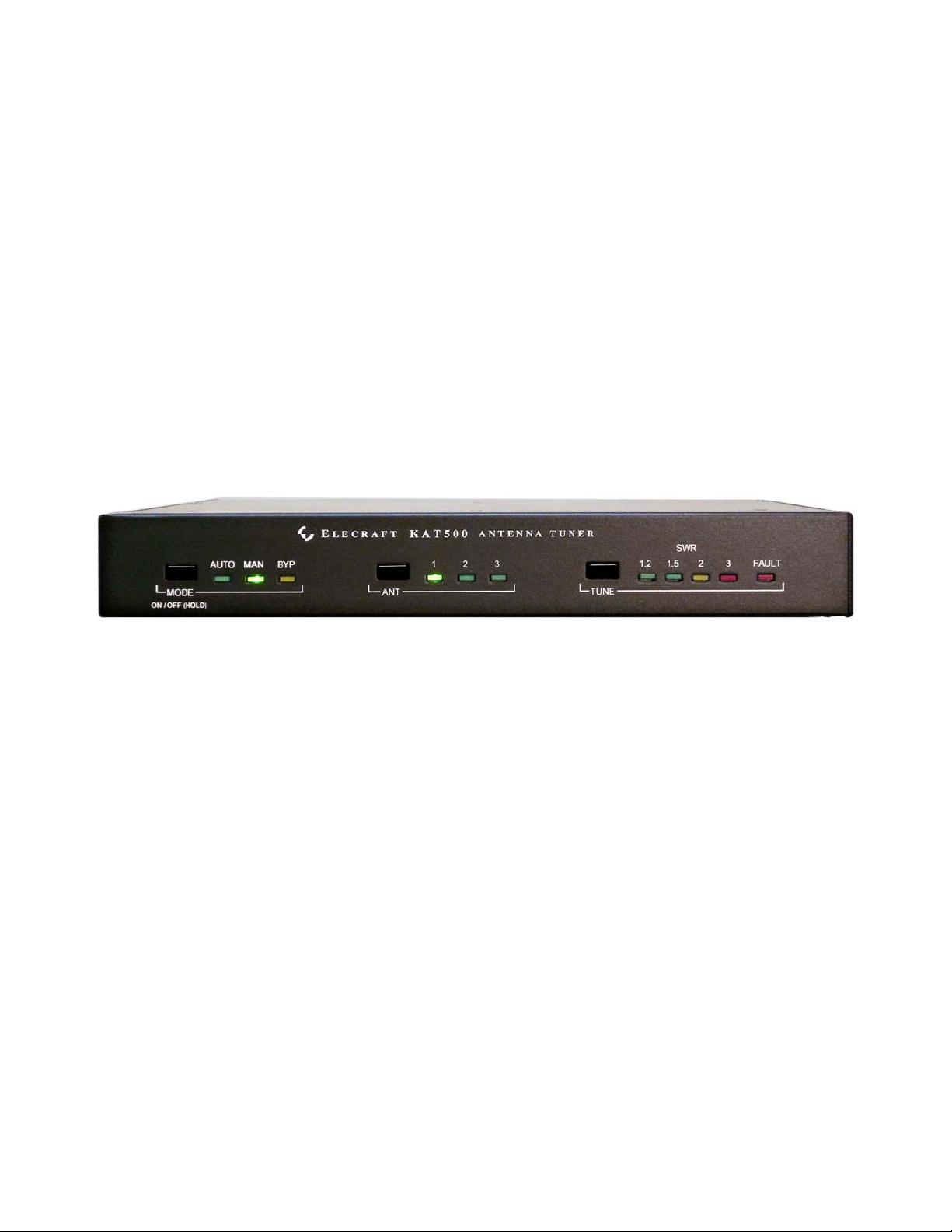
Operation
Figure 4. KAT500 Front Panel Controls.
Tuning
Be sure the KAT500 is connected to your station equipment as shown under Cabling (pg 5).
Apply power to the KAT500. It will turn on automatically.
Tap
Tap
Tap
Apply RF power between 10 and 100 watts. Most transceivers produce RF in this range when
After successfully tuning, the KAT500 stores the settings and antenna selected in memory from which it
is recalled almost instantly when returning to that frequency later. The entire spectrum from 1.8 through
54 MHz is divided into frequency segments and the tuning information is stored for each segment. Since
retuning is normally required over a narrower frequency range on the lower frequencies to maintain a low
SWR, the lower frequencies have narrower segments assigned as follows:
Below 3 MHz the segments are 10 kHz wide.
From 3 MHz through 26 MHz the segments are 20 kHz wide.
From 26 MHz to 38 MHz the segments are 100 kHz wide.
From 38 MHz to 54 MHz the segments are 200 kHz wide.
MODE, if necessary, to select AUTO.
ANT to select the antenna you wish to use.
TUNE. AUTO will begin to flash.
driving an external amplifier. The KAT500 will open the key line to disable the external amplifier
so the transceiver drives the KAT500 directly during the tune cycle. You will hear relays
operating until the selection of inductance and capacitance has been found that yields a low SWR.
(See Fault Conditions on pg 13 if the
the
TUNE LEDs. The KPA500 Utility program (pg 14) may be used to display a more accurate
SWR reading.
FAULT LED lights.) An approximate SWR is indicated on
AUTO mode, if you QSY such that the SWR rises above 1.8:1 the KAT500 will automatically retune
In
when you transmit on the new frequency. The KAT500 will open the key line to disable your amplifier
briefly until the tune cycle is completed. The new frequency and settings are stored in memory.
If the SWR measured by the KAT500 is 1.2:1 or below, the KAT500 automatically switches to bypass in
that frequency segment.
If the SWR remains above 2.0:1 after a tune operation, the KAT500 will hold the key line open to protect
your amplifier from the high SWR load.
11
Page 12

The SWR limits that initiate an automatic
TUNE in AUTO, switches the KAT500 to bypass or which
causes the KAT500 to hold the key line open to protect the amplifier can be changed using the Utility
Program. See KAT500 Configuration (pg 14) for details.
You can prevent automatic tuning by selecting the MAN (manual) mode. In MAN, the KAT500 will
automatically choose a new tuner setting based on the band and antenna selected, but you must tap
TUNE
and then apply RF power to initiate a tuning operation if needed.
BYP mode bypasses the KAT500 completely, routing the RF input to the selected ANT connection.
OPERATING TIP: If you want quick QSY capability, do a tune operation as
described above on your favorite frequencies, using each antenna you might select. This
stores the correct settings in the KAT500 memory so they will be recalled almost instantly
when you return to that frequency. If you have changed your antenna system, it may be
helpful to use the KAT500 Utility program to erase the previously stored data before
tuning again to establish the new settings (see Utility Program, page 14)
Fine Tuning
If a tune operation results in an undesirably high SWR, you can immediately order another tuning cycle
by tapping
settings just found, but using finer step sizes in L and C values. This may result in a lower SWR. The new
values are stored and will be used when returning to this frequency.
You can also manually adjust the L and C values using the KAT500 Utility Program (page 14). Load the
Utility program, click on the
up and down arrows. When finished, click on
TUNE again within 5 seconds. The KAT500 will repeat the tune operation starting with the
OPERATE tab and then adjust the L and C values using the radio buttons or
MEMORIZE to store the new settings.
Cancel Tuning
Tap TUNE to cancel a tune command.
Alternate Tuning Commands
A TUNE command can be initiated through the RS232 port using the KAT500 Utility program. Load the
Utility program, click on the
You can initiate a
TUNE command through the rear panel TUNE jack (see Figure 3) with a transceiver
using the AH-4 protocol or by momentarily shorting the ring to ground.
OPERATE tab and then click on TUNE.
12
Page 13

Bandswitching
Some non-Elecraft amplifiers may be damaged if the KAT500 opens the key line while the amplifier is
producing full RF output. This can happen when changing bands because the KAT500 senses the
frequency of the RF signal, opens the key line, and then switches to the settings for that frequency from
memory or initiates a tune operation.
The KPA500 amplifier is designed to have the key line interrupted while producing full output without
damage. The DB15 interface cable between the K3, KAT500 and KPA500 (Figure 1 cable
cable
), ensures that the KPA500 amplifier and KAT500 change bands at the same time as the K3.
or Figure 2
CAUTION:
When using a non-Elecraft
Place the amplifier in standby.
Switch the transceiver or transmitter to the new band.
If needed, manually switch the amplifier to the new band.
If your amplifier requires manual tuning, connect it to a suitable dummy load. (You can
attach the dummy load to one of the KAT500 antenna connectors, switch the KAT500 to
BYP and select that connector with the ANT switch.) Tune up your amplifier into the
dummy load per the manufacturer’s instructions. Return the mode to
Generate a CW signal from your transceiver or transmitter between 20 and 100 watts. This
will allow the KAT500 to change bands, change antennas, if required, and switch to the
tuning values for that frequency stored in memory or perform a tune cycle, if needed.
Switch the amplifier from standby to operate.
amplifier, change bands as follows to avoid damage to your amplifier.
AUTO when finished.
Turning the KAT500 Off
Hold MODE or remove power to switch the KPA500 off. When off, ANT 1 is automatically selected.
Unused antenna connections are not grounded but the KAT500 contains a resistor to bleed off normal
static buildup.
Fault Conditions
A fault will occur if:
The RF drive power exceeds 110 watts during a
damage due to excessive RF power while switching. If this fault occurs, be sure you have the PA
Key circuit installed, either through the DB15 intereface cable or using separate key line cables
(see Cabling, pg 5).
The impedance of your antenna is outside of the tuning range so an acceptable SWR cannot be
found.
Reset the fault by tapping the TUNE switch or cycling power off, then on again with the
TUNE operation. This protects the relays from
MODE switch.
13
Page 14

Utility Program
To use the Utility Program you will need:
A personal computer.
The KAT500 Utility Program available free from Elecraft at www.elecraft.com
The RS-232 cable with a USB connector supplied with your KAT500.
Connect your computer to the KAT500 using the interface cable connected to the PC DATA jack and
load the Utility Program. Click on the
communicate with the KAT500. Click on
that the Utility program is communicating with the KAT500 if everything is working properly.
Detailed operating instructions for the Utility program are provided in the Utility Help screens.
PORT tab and select the port your computer is using to
TEST COMMUNICATIONS and you will see a pop-up stating
.
KAT500 Configuration
You can configure the KAT500 to best support your installation. Click on the Utility program
CONFIGURATION tab and then on the Per Band Configuration button. After making your choices, click
on the
APPLY button at the bottom.
Antennas
You can select which antenna connectors are active (Enabled) on each band. Antenna connectors are
disabled by clicking on the check mark to clear it. Disabling antenna connectors will cause them to be
skipped over when cycling through the options with the front panel
tab. You can also select which
selected when you return to that band. You can change the selection to any other antenna connector, using
provided it has not been disabled.
ANT connector you prefer to use on each band and it will be automatically
ANT switch or in the Utility Operate
Thresholds
You can set the SWR thresholds above which a tuning cycle will be started in AUTO mode, or below
which the KAT500 will automatically switch to bypass. Also, you can set an SWR threshold at which the
key line will not close to enable the external amplifier to protect it from excessive SWR.
These thresholds can be set the same for all bands, or individual values can be entered for each band.
Memories
You can erase all of the stored tuning memory data for the entire KAT500, or just the memories
associated with a particular
ANT selection and band.
Saving Configuration
You can save the configuration to a file on your computer so that you can restore it quickly without
needing to re-enter the data.
14
Page 15

Parameter Initialization (EEINIT)
It is possible, though rare, for parameters to become altered in such a way as to prevent the firmware from
running correctly. If you suspect this, you can reinitialize parameters to defaults, then restore a
previously-saved configuration (or restore the configuration manually using the utility program).
1. Click on the
2. Type
3. Restore your configuration, either from a previously-saved configuration file or manually as
EEINIT;
described under KAT500 Configuration above.
Command Tester tab.
Updating Firmware
Although the KAT500 is shipped with current firmware installed, from time to time updated and
improved firmware may become available.
To update firmware, connect your KAT500 to your computer and launch the KAT500 Utility program.
Updated firmware may be obtained in two ways.
1. Click on
latest production released firmware or,
2. Download the new file from the Elecraft web site manually and place it in a local folder, then
click on Browse… to locate the folder on your computer. This is the way to access the latest Beta
firmware available from Elecraft.
To install new firmware in your KAT500, click on the utility
start the transfer. Follow any on-screen instructions.
Be sure to check the notes supplied with the new firmware. They may include changes that affect the
instructions in this manual.
Firmware tab and then the Click on Copy Firmware Files from Elecraft to download the
Send Firmware to the KAT500 button to
If you don’t have Internet access, you can obtain a firmware upgrade on CD. If you don't have a
computer, you can send your KAT500 to Elecraft to be upgraded. See Customer Service and Support,
pg 3.
15
 Loading...