

Page 1

E L E C R A F T K A T 1 A U T O M A T I C A N T E N N A T U N E R
Assembly and Operating Instructions
Revision C, Jan. 18, 2001. Copyright © 2001, Elecraft; All Rights Reserved
Introduction
The KAT1 internal automatic antenna tuner (ATU) allows nearly any random-length wire antenna to be
connected directly to the Elecraft K1 transceiver and used on one or more bands. The L-network
configuration can be used with coax-fed or end-fed wire antennas, or with balanced feedlines via a balun.
Unlike some internal auto-tuners, the KAT1 functions on receive as well as transmit. This provides an
increase in receive sensitivity and improves rejection of out-of-band signals.
The KAT1 uses latching relays to reduce current drain to nearly zero except when actually tuning. These
relays select appropriate combinations of inductance and capacitance, as well as either a capacitor-in or
capacitor-out L-network configuration. Tune-up is controlled by the KAT1's microprocessor, which also
supplies SWR or power information to be displayed on the K1's LCD. Once a match has been found,
matching parameters are saved so that the settings can be recalled immediately on any band change.
ATU parameters (L, C, SWR, etc.) can be viewed using the K1’s menu. Additional menu entries are
provided to do component-level troubleshooting all relays, inductors, and capacitors.
In addition to being one of the world’s smallest automatic antenna tuners, the KAT1 is very easy to build
and install. The KAT1 module plugs directly into the K1’s Filter board with no additional wiring. Gold
plated connectors and redundant connector pins are used to provide excellent reliability for field operation.
Specifications
L - C Ranges L: approx. 0-5 µH in 16 steps; C: approx. 0-300 pF in 32 steps
Network Type L-network (series L, shunt C); C switchable to transceiver or antenna side
Tuning time 1 to 8 seconds typical for initial tune-up; < 1/2 sec. to recall per-band settings
SWR Display 1.0:1 to 9.9:1
Current Drain Approx. 10-30 mA during TUNE; < 5 mA at all other times
Size 5.0" (L) x 1.8" (D) x 0.5" (H) (12.7 x 4.6 x 1.3 cm)
i
Caution: Some components in this kit can be damaged by static discharge. Before handling any
transistors or integrated circuits, always put on an anti-static wrist strap or touch any grounded, unpainted
metal surface.
1
Page 2

Parts Inventory
The table below lists all parts in the kit. The K1 Owner's manual has photographs of similar parts.
Ref. Description Part No. Qty
C1 Capacitor, 10 pF, 500 V NPO disc E530026 1
C2 Capacitor, 22 pF, 500 V NPO disc E530027 1
C3 Capacitor, 39 pF, 500 V NPO disc E530028 1
C4 Capacitor, 82 pF, 500 V NPO disc E530029 1
C5 Capacitor, 150 pF, 500 V NPO disc (“151”) E530030 1
C11, C12, C17 Capacitor, .001 µF, 25 V("102") E530001 3
C13, C14, C16,
RF-C76
C15 Capacitor, .047 µF, 25 V ("473") E530025 1
C10 Capacitor, 100 pF, 200 V, NPO disc ("101") E530034 1
C9 Ceramic trimmer, 5-30 pF E540001 1
D1, D2 Diode, 1N5711 E560004 2
D3 Diode, 1N34A E560000 1
FIL-J1 Conn., 3-pin female, 0.1” spcg., Samtec SSW-103-01-G-S E620009 2
FIL-J2 Conn., 5x2 female, 0.1” spcg., Samtec SSW-105-01-G-D E620045 2
K1-K10 DPDT latching relay E640001 10
L1-L4 Toroidal inductor, T37-2 core (RED); see text E680006 4
P1 Conn., 3-pin male, .1" spcg., Samtec MTSW-103-22-G-S-420 E620046 1
P2 Conn., 5x2 male, .1" spcg., Samtec MTSW-105-22-G-D-420 E620047 1
R1, R2 Trimmer potentiometer, 100K E520001 2
R5 Resistor, 100 ohms, 5%, 1/4-watt (brown-black-brown) E500010 1
R3 Resistor, 200 ohms, 5%, 1/4-watt (red-black-brown) E500020 1
R6 Resistor, 1 k, 5%, 1/4-watt (brown-black-red) E500013 1
RF-R39 Resistor, 1.8 k, 5%, 1/4-watt (brown-gray-red) E500004 1
R4 Resistor, 3.3 k, 5%, 1/4-watt (orange-orange-red) E500017 1
RF-R4 Resistor, 5.6 k, 5%, 1/4-watt (green-blue-red) E500007 1
RFC1 RF choke, 82 µH, miniature (gray-red-black) E690003 1
T1 Toroidal transformer, FT37-43 core (gray); see text E680003 1
U1 IC, Microcontroller, 16C72A or 16F872 E610007 1
U2 IC, Op-amp, LM358 E600010 1
Z1 Ceramic resonator w/internal capacitors, 4.0 MHz E660001 1
HDWR Socket for U1, 28 pins E620011 1
HDWR #4 split lock washer (2 spares) E700004 4
HDWR 4-40 x 1” ZN ST Phillips machine screw (2 spares) E700047 4
HDWR Standoff, 3/16” dia. x 5/8”, #4 hex, RAF #1323-4-A E700048 2
MISC Enamel wire, #26 Thermaleze, GREEN E760004 2 ft.
MISC Enamel wire, #26 Thermaleze, RED E760002 5 ft.
MISC Hookup wire, #24 insulated E760005 3”
MISC KAT1 PC board E100112 1
Capacitor, .01 µF, 25 V ("103") E530009 4
2
Page 3
K1 Firmware Requirements
To use the KAT1 antenna tuner, you'll need K1 main processor firmware revision 109 or later. (The main
processor is U1 on the Front Panel board.) To check the firmware revision, hold any switch when powering
up the K1. When you release the switch, the firmware revision will be shown on the LCD.
KAT1 PC Board Assembly
i
A fine-point, temperature-controlled soldering iron (700-800 degrees F) is required to assemble
this kit. A high-wattage iron or one with a wide tip may damage components, pads, or traces. Use a
minimum amount of solder to avoid ground shorts.
since removing parts from double-sided PC boards can be difficult.
component outline, but do not solder. Do not bend the relay leads. Note: The reference designators for the
relays may be difficult to read on the rev. C board. They are sequential, starting from the left with K1.
the first row. Do not solder yet.
over. Solder two diagonal corner pins on each relay.
i
Install components only in the order described below. Double-check all values before soldering,
Place relays at locations K1-K5, with the white-striped end of each relay oriented as shown by its
Place relays at locations K6-K10. This second row of relays faces in the opposite direction from
Using a book or other flat object to hold the relays in place on the top side of the board, flip the board
Inspect all 10 relays closely to make sure that they’re seated flat against the PC board. If not, re-heat
the corner pins one a time while pressing down on the relay. Once all relays are properly seated, solder the
remaining pins.
Install the 28-pin IC socket at U1. The notched end of the socket must be aligned with the notched
end of the component outline.
Install the following resistors, starting with R6 in the upper left-hand corner of the board:
__ R6, 1k (brown-black-red) __ R5, 100 ohms (brown-black-brown)
__ R4, 3.3k (orange-orange-red) __ R3, 200 ohms (red-black-brown)
Install the three diodes, with the banded end of each diode oriented as shown on the board. D1 and D2
are type 1N5711. D3 is a type 1N34A, with a larger glass body. Note: On the revision C PC board, D3 may
be a tight fit. Pre-form the leads if necessary.
Install potentiometers R1 and R2 as indicated by their outlines. Make sure they are fully seated on the
PC board and are not tilted. Trim the leads after soldering. This is necessary to prevent shorts when the
KAT1 is installed above the Filter board.
3
Page 4
Install RF choke RFC1, which is located near U1.
Ceramic resonator Z1 looks like a capacitor with three leads. Install Z1 (to the left of U1). Be careful
not to overheat the resonator when soldering, as this can alter the resonant frequency. Keep soldering time
to 1-2 seconds per lead. Trim the leads after soldering.
Install the LM358 IC at U2, with the notched or dimpled end oriented as shown by the component
outline. Bend two corner pins to hold the IC in place, then solder.
Install the trimmer capacitor, C9. The flat side of C9 should be oriented to the left as indicated by its
outline.
Install the following capacitors. Note: On the rev. C PC board, the pads for C5 (150 pF) and C17
(.001 µF) may not be spaced perfectly for the supplied capacitors. You may need to pre-form the leads
before installation.
__ C1, 10 pF __ C2, 22 pF __ C3, 39 pF __ C4, 82 pF __ C5, 150 pF (151)
__ C11, __ C12, and __ C17, .001 µF (102) __ C13, and __ C14, .01 µF (103)
__ C15, .047 µF (473) __ C16, .01 µF (103) __ C10, 100 pF (101)
i
In the following steps, inductors L1 through L4 will be wound and installed. There is no need to
adjust the windings to precisely match the inductances shown on the schematic.
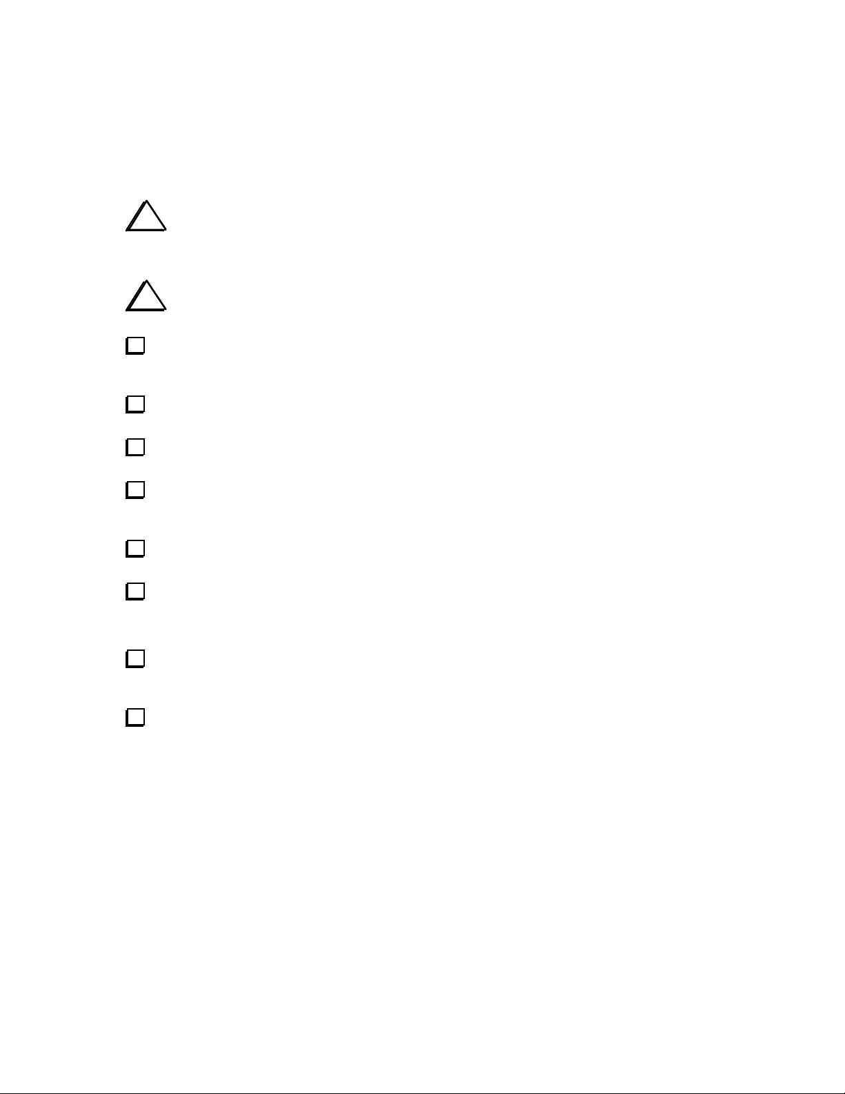
inductor, pass the long end of the wire through the core exactly 8 times. Each pass through the core counts
as one turn. The finished winding should look like the illustration below. Exact turns spacing is not critical.
Inductor L1 is wound on a T37-2 core (red) using 6" (15 cm) of #26 red enamel wire. To wind the
Remove insulation
Spread out the turns of L1 so they occupy about 80-90% of the core’s circumference.
4
Page 5
Cut L1's leads to about 1/2" (12 mm) long. Completely remove the enamel insulation from the leads
to within 1/8” (3 mm) of the core. The enamel wire provided can be heat-stripped using a small amount of
solder on the tip of your iron. Stripping using this method takes 4-6 seconds.
Install L1 vertically on the PC board as shown by its component outline, then pull the leads taut on
the bottom of the board.
Trim and solder the leads of L1. When soldering, make sure that the solder binds well to the leads. If
the lead appears to be an "island" in a small pool of solder, chances are it is not making good contact.
Measure from pad to pad using an ohmmeter to verify the connection.
Wind and install L2 through L4 using the same procedure you used for L1. The number of turns and
wire length for each inductor is shown below.
__ L2, 12 turns (8" [20 cm]) __ L3, 17 turns (11" [28 cm]) __ L4, 25 turns (15" [38 cm])
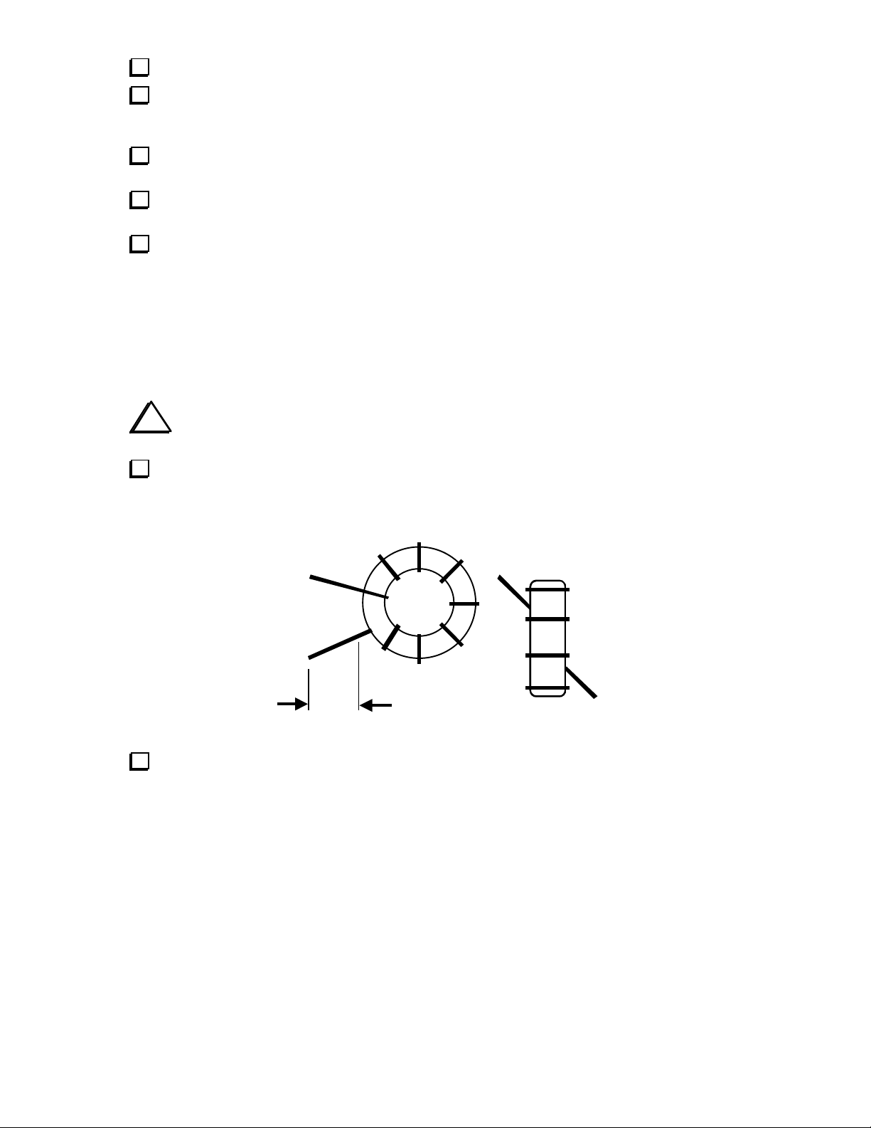
T1 is wound on a ferrite toroidal core (gray, FT37-43). Cut two 10" (25 cm) lengths of #26 enamel
wire, one red and one green. Twist the two wires together, crossing over each other about 3 to 4 times per
inch (1-2 times per cm). Then wind the twisted wires onto the core as shown below, using 10 turns. Each
pass through the core counts as one turn, and turns spacing should closely resemble the illustration.
i
The wires labeled (1) and (3) should originate from below the core, and wires (2) and (4)
from above it, as shown below. This will ensure that the transformer has the correct phasing.
4 (RED)
2 (GRN)
1 (GRN)
3 (RED)
Trim the leads of T1 to about 1/2" (12 mm) long. Completely remove the insulation from T1's leads
up to the edge of the core, using a solder pot or hot soldering iron tip. Do not attempt to burn off the
insulation using a match or lighter, as the flame may fuse the pairs of wire together, causing them to
become shorted. Another way to remove the insulation is to use fine sand paper.
5
Page 6

Tin T1's leads with solder. If the leads do not tin easily, the insulation may not be fully removed.
Using an ohmmeter, measure between the red and green wires to make sure that they're not shorted.
Install T1 as indicated by its PC board outline near the right end of the board. Insert the leads into the
numbered holes as shown by the drawing of T1. Pull the leads taut on the bottom of the board. Before
soldering, make sure that the entire portion of exposed lead is properly tinned.
Cut a 1-1/8" (2.9 cm) length of insulated, solid-conductor hookup wire. Remove 1/4" (6 mm) of
insulation from each end. This jumper will form the 1-turn link winding of T1.
Insert this wire through the center of T1 and into the pad labeled 5. Bend the wire down to the left and
insert the other end into pad 6. Pull the leads of the wire taut on the bottom of the board, then solder.
Install the 3-pin male connector, P1, on the bottom of the ATU board as shown below. Before
soldering, make sure the connector is seated flat against the board and is not tilted. If the connector is not
mounted correctly, it may be difficult to plug the ATU board into the Filter board.
Install the 10-pin, dual-row male connector, P2, on the bottom of the ATU board. As with P1, make
sure the connector is seated completely flat against the PC board.
Straighten the pins on U1 (16C72A). Refer to Figure 4-6 in the K1 owner’s manual if necessary.
Install U1 in its socket, noting the orientation of pin 1, which is label on the board.
Form a discarded component lead into a small U-shape, and install it between the two pads labeled
with a ground symbol (lower left-hand corner of the PC board). Solder the jumper on the bottom of the
board.
6
Page 7

K1 Filter Board Preparation
Remove the K1’s top cover (four screws).
Remove the three screws holding the Filter board in place, and unplug the board.
Install a 3-pin female connector (FIL-J1) on the top side of the Filter board. Before soldering, make
sure that the connector is flat against the board and is not tilted.
Remove the jumper between pins 2 and 10 of J2 on the Filter board. Wick out any residual solder.
Install a 10-pin, dual-row female connector (FIL-J2) on the top side of the Filter board. Before
soldering, make sure that the connector is flat against the board and is not tilted.
If you have any additional Filter boards, repeat the previous three steps for each one.
If any of your Filter boards are not aligned, you should align them now as described in the K1
owner’s manual. Filter board alignment cannot be done with the KAT1 installed, since the KAT1 module
prevents access to the slug-tuned inductors. See page 40, Band-Pass Filter Alignment, and page 46,
Preparation for Transmit Alignment.
K1 RF Board Preparation
Remove the K1’s bottom cover (four screws, plus the connector hardware).
Locate R36 on the RF board, near the antenna jack. Unsolder the lead of R36 that is closest to the
jack. Bend the resistor up and away from the board, but do not remove it completely. Note: R36 will need
to be re-connected if you have to align a new Filter board.
i
The following five steps are only necessary if you have revision D or earlier of the K1 RF
board. On later revisions, these parts will already have been installed during RF board assembly.
ground, if you haven’t already. This is described in detail on page 31 of the K1 owner’s manual (right
column, last assembly step).
leads, and fold the capacitor down so it won’t hit the bottom cover.
Install resistor RF-R39 (1.8 k, brown-gray-red) on the bottom of the RF board between Q14 base and
Solder capacitor RF-C76 (.01 µF, “103”) across RF-R39, the resistor in the previous step. Use short
7
Page 8

On the bottom of the RF board, locate the label DRV. Just to the right of the letter V in DRV is a
H
trace segment about 1” (2.5 cm) long, with four 45-degree bends (see below). Carefully cut this trace in
approximately the location shown, using a sharp knife or hand milling tool. Use an ohmmeter to verify that
the trace is cut.
DRV
Solder resistor RF-R4 (5.6 k) on the bottom of the board between the two pads located at either end of
the cut trace segment. Use the minimum lead length necessary. Position the resistor so that its leads do not
touch any adjacent pads or traces. Solder the resistor on the bottom of the board.
If you plan to use the KAT1 on 80 meters, install a 100-µH RF choke on the bottom of the RF board
as described in the K1B80 errata sheet. The RF choke is supplied with the 80-meter band kit.
ERE
CUT
DRV
RF-R4
Filter Board and KAT1 Module Installation
Plug in the Filter board you plan to use, being very careful to line up all 8 pins of each of the three
connectors. To hold the Filter board in place, use only the middle of the three screws. The two screws at the
ends of the Filter board will not be needed, because the KAT1 module’s screws will be inserted here.
Set one 5/8” long unthreaded standoff on top of each of the two holes at the ends of the Filter board.
These standoffs must not be left out, since they establish the spacing between the two boards.
Plug the KAT1 module into the Filter board, being careful to line up all pins of the 3-pin and 10-pin
connectors.
The two 5/8” long standoffs should now be visible through the holes at each end of the KAT1
module. Use two 1” long 4-40 screws and two #4 split lock washers to hold the KAT1 to the Filter board.
8
Page 9

Initial Test
Connect a power supply or battery to the K1 and turn on power. If you see or smell smoke, turn
power OFF immediately. Check all connections and refer to the Troubleshooting section if necessary.
Tap M E N U and scroll through the entries until you find A T U . To select the mode for the ATU, hold
E D I T . If you see three dashes (- - - ) instead of the A T U parameter, refer to Troubleshooting.
Step through the A T U menu parameters using W P M + and W P M - . Each menu entry will be
explained in the Using the ATU section.
Set the A T U parameter to L 0 . You should hear a relay switch when you move from L 0 to L 1 , then to
L 2 , etc., up through L 4 . The same should be true for C 0 through C 5 , as well as N 1 and N 2 . If you don't
hear any relays switching, see Troubleshooting.
Connect a 50-ohm dummy load to the K1’s antenna jack (5W or higher rating). Use the O U T menu
entry to set power to 5 watts.
Set the A T U parameter to F x . x (KAT1 firmware revision). You should see F 1 . 1 (or higher). Exit
the menu, then hold
W P M + and W P M - together to go into TUNE mode: you should see r 8 . 5 .
Immediately tap any key to exit TUNE.
Note:
r 8 . 5 is an SWR test value only, showing whether digital data is being transmitted successfully from
the KAT1 to the K1 in TUNE mode.
SWR Bridge Adjustment (C9)
Make sure a 50-ohm dummy load is connected to the antenna jack.
Select band 1 (the lower of the two bands).
Set the A T U parameter to C L S (Calibrate SWR) using the menu.
Set power output for 5.0 watts using the O U T menu entry. Exit the menu.
Pre-set potentiometers R1 and R2 on the ATU board to about 60% of full clockwise rotation.
Connect the positive lead of a DMM or analog voltmeter to the point labeled TP1. Connect the
negative lead to the nearby ground jumper.
Locate a non-metallic tuning tool for adjusting ceramic trimmer C9. An alternative is to use a very
small flat-blade screwdriver or jeweler’s driver, with tape wrapped around the metal shaft to prevent you
from contacting it.
Enter TUNE mode by holding W P M + and W P M - together. Adjust C9 for the lowest possible
voltmeter reading. (The null may be sharp.) Cancel TUNE mode by tapping any switch other than
W P M +
or W P M - .
9
Page 10

Power Calibration (R1 and R2)
i
The KAT1 will provide accurate power readings only if properly calibrated. This requires
an external wattmeter or an RF probe and digital multimeter (DMM). Appendix E of the K1 Owner’s
Manual shows how to construct a suitable RF probe.
dummy load to the wattmeter’s output jack. Use short lengths of good-quality coax.
the shortest possible leads. Connect the tip of the RF probe to the “hot” lead of the dummy load, and the
probe’s ground clip to the dummy load’s chassis or RF ground. Connect the DC outputs of the RF probe to
your DMM, and set the DMM for DC volts (20 or 30 volt scale).
seconds), tap
so that the K1’s LCD shows the same power.
W P M + or W P M - until the DMM shows about 14 VDC. Then adjust R1 on the KAT1 so that the K1’s
LCD shows about 5.0 watts.
Note: The power indicated when using when using an RF probe will vary somewhat from band to band due to the stray
reactance of both the tuner and the probe. Also, the probe’s diode may not perform as efficiently on the higher bands.
This is why we recommend doing the C L P adjustment on the lower of the K1’s two bands.
If you have an external wattmeter: connect its input jack to the K1’s antenna jack. Connect a 50-ohm
If you’re using an RF probe: connect a 50-ohm dummy load directly to the K1’s antenna jack using
Select band 1 (the lowest-frequency band).
Use the O U T menu entry to set the K1’s output to 5 . 0 watts.
Use the A T U menu entry to set the ATU’s mode to C L P (Calibrate Power), then exit the menu.
If you have an external wattmeter: Enter TUNE mode. Once the power has stabilized (about two
W P M + or W P M - until the wattmeter shows close to 5.0 watts. Then adjust R1 on the KAT1
If you’re using an RF probe: Enter TUNE mode. Once power has stabilized (about two seconds), tap
Adjust R2’s rotation to match that of R1 (visually).
Final Assembly
Turn off the K1 and disconnect the power source.
Re-install the bottom cover and the connector hardware.
Due to the height of the ATU board when installed, the rear-most lug on the speaker may touch the
case of one of the ATU’s relays. To avoid this, fold the speaker lugs as flat as possible; make sure they’re
not shorted to the speaker frame.
Plug in the speaker. Route the speaker cable along the K1’s right side panel, away from the ATU
board and the front panel. This will minimize stray RF pickup.
Re-install the top cover.
10
Page 11

Using The ATU
Caution: Never touch an exposed antenna wire when transmitting. If you ever feel an RF burn or
shock when touching the K1 chassis or key, see Antenna Considerations.
Basic ATU Operation (TUN)
To tune up an antenna using the KAT1:
• Use the K1 menu to set the ATU’s operating mode to
• Connect an antenna and ground to the K1. (You can use most coax-fed antennas, as well as
end-fed wires connected directly to the K1 with no coax. Use a balun with balanced feedlines.)
• Enter TUNE mode. Power will be reduced to about 1.5 watts and displayed briefly, then SWR will be
displayed while the ATU matches the transmitter to the load (usually 1-5 seconds). If the match is
already very good (< 1.2:1), the tuner’s L and C settings will not be changed.
• When you no longer hear any relays switching, tune-up has completed, and the final SWR is
displayed. At this point you can optionally tap
Pressing any other switch or tapping the key will cancel TUNE and restore your specified power.
• ATU settings are stored in EEPROM, and will be recalled instantly whenever you change bands.
Displaying Power Output (OUT)
To display forward power without changing the present L and C settings:
• Change the
• Enter TUNE mode; forward power will be displayed until you tap any switch.
• If the actual power output is lower than you selected in the menu, you may have it set higher than the
K1 is capable of on the present band. Always set power to a level at or below the maximum that
the K1 can achieve. Use lower power when running from a battery.
Displaying
To display SWR without changing the present L and C settings:
• Use the menu to change the
Example: r 1 . 2 means that the last SWR reading was 1.2:1.
• Enter TUNE mode; the present SWR will be displayed until you cancel by pressing any switch.
Power will be reduced to about 1.5 watts whenever SWR is displayed.
A T U mode from T U N to O U T and exit the menu.
SWR (rx.x)
A T U mode from T U N to r x . x (the most recent SWR reading).
T U N (auto-tune), then exit the menu.
W P M + or W P M - to change the selected power level.
Using an External Antenna Tuner (CLS and CLP)
If you're using an external antenna tuner you can still use the KAT1 to display SWR or power:
• Set the ATU mode to C L S (for SWR display) or C L P (for forward power display). In both cases,
the L and C in the matching network will be set to zero.
• Enter TUNE mode. In the case of
be displayed. In
C L P mode, power will be displayed, and will not be reduced.
C L S , power will be reduced to about 1.5 watts, then SWR will
• Adjust the external antenna tuner. Once tune-up is completed, exit TUNE mode as usual.
11
Page 12

Important ATU Operating Tips
• A 1.0:1 SWR is not necessary for good performance. See Antenna Considerations.
If the final SWR is above 3:1, you may want to use lower power or re-configure
your antenna. (The impedance matching range is reduced on 80 meters.)
• If you switch between the various ATU modes frequently, you can assign the
to the programmable function switch,
• If you use
D I S P L A Y to put the K1 into supply voltage display mode, then enter TUNE, you'll
P F n (see the K1 Owner's Manual for details).
A T U menu entry
see the transmit-mode battery voltage, not SWR or power output. The ATU settings will not change.
• The ATU menu entry can be used to display the current values of L, C, network type, and other data.
See ATU Modes for a full listing of all status displays.
ATU Modes
Table 1 lists all of the KAT1’s operating modes, and what is displayed when TUNE is activated in each
mode. The ATU’s
T U N mode is used for normal operation. In this and all other modes where SWR is
displayed, power is dropped to approximately 1.5 watts during TUNE. You can override this level by
setting power lower using the
O U T menu entry. However, if you see P L O on the LCD during TUNE, you
may have power set too low to obtain a stable SWR reading.
The other modes are primarily used for calibration and troubleshooting:
• In C L S mode (as well as C L P ), the L and C relays are all reset (L and C = zero).
• The L 0 -L 4 , C 0 -C 5 , N 1 , and N 2 modes select individual L/C/net relays for test purposes.
Note: In modes
See Troubleshooting for details on how to make use of these modes.
L 0 -L 4 , capacitance is set to 0. In modes C 0 -C 5 , the inductance is set to about 1 µH.
• The F x . x menu entry shows the firmware revision. If you enter TUNE in this mode you should
see
r 8 . 5 , which is a test pattern for the digital SWR data sent over the RFDET/DATA line.
Table 1. ATU Modes
Mode Description T U N E Mode Description T U N E
CLP Used for calibration of R1; L/C =
0
CLS SWR bridge only; L/C = 0 SWR Exx 1-49 = error (see Troubleshooting) SWR
TUN Auto-tune mode SWR Fx.x KAT1 firmware revision, e.g. F1.0 r 8 . 5
OUT Forward power display Power L0-L4 Individual inductor test (C = 0) SWR
rx.x SWR from most recent TUNE SWR C0-C5 Individual capacitor test (L = 1 µH) SWR
Lx.x Inductance, µH (present band) SWR N1 Network relay test, Cin (L/C = 0) SWR
Cxx Capacitance, pF x10 (present band) SWR N2 Network relay test, Cout (L/C = 0) SWR
Power NTx 1=Cin, 2=Cout (present band) SWR
12
Page 13

Antenna Considerations
An antenna tuner will not improve your antenna–it can only tune out the antenna's reactance. In general,
use the longest, highest antenna you can put up, and keep the antenna away from power lines and buildings.
The KAT1 will work with a wide variety of antennas, some of which are covered below.
Ground System
A good ground system will provide efficient radiation, better antenna loading characteristics, less RF on the
chassis, and safer operation. Use a minimum of two radials, cut to 1/4 wavelength on the lowest band used.
Do I Need a 1:1 SWR?
No—this is a common misconception. For example, if the SWR is 2:1, the loss in transmitted signal
strength will be only about 0.5 dB. Of course the KAT1 always tries to hit 1:1, and with most antennas it
will find an SWR below 1.5:1 on most bands. If the SWR is higher than 3:1, try using a balun (see below).
Resonant and Multi-Band Antennas
With resonant antennas such as dipoles, beams, or verticals, the KAT1 will typically improve the match on
each band used. It may also allow operation on additional bands, although with beams, the radiation pattern
may change completely. With short, loaded whips the tuner may provide multi-band coverage, but such
antennas are generally ineffective due to the low radiation resistance. We recommend random-wire
antennas for portable use (see below).
One useful trick with coax-fed antennas is to short the center conductor and braid together and treat the
system as if it were a random wire. This may allow you to operate well below the antenna’s intended bands.
Random-Length Antennas
The KAT1 is optimized for use with long, random-length wire antennas, since these are the easiest
antennas to set up in the field (you just toss the wire in a nearby tree). In most cases you can connect such
an antenna (and a few ground radials) directly to the K1, with no feedline. However, watch for RF
problems, especially if the wire is exactly a half-wavelength long or any multiple thereof on a given band.
The KAT1 also works with loops. An untuned loop of wire 30 feet long (or longer), formed into any shape,
can be matched on most bands. A loop may work well even if you can’t lay out a lot of ground radials.
Using Baluns and RF Isolation Chokes
A balun converts a balanced antenna or feedline to unbalanced (one side grounded) to work with your
tuner. A balun can also perform an impedance transformation and/or help isolate the antenna from the rig to
reduce RF pickup. You may need a balun if: (1) you're using balanced feedline; (2) you're having trouble
matching an antenna on one or more bands; (3) you notice RF feedback or get an RF burn. A low-loss,
broad-band, 4:1 balun is a good choice, and may solve all three problems. A 9:1 or 4:1 balun is often used
with open-wire line. A 1:1 balun or coaxial isolate choke (current balun) will also work in many cases.
Balun design is covered in many publications, including the ARRL Handbook. Also check the Elecraft web
site (www.elecraft.com) for antenna-related application notes.
13
Page 14

Troubleshooting
If the ATU menu parameter shows "- - - " at all times, make sure you have revision 109 or later of the
K1 main processor firmware. Other possibilities include a connector shifted by one position, an unsoldered
pin, etc. Check the ATU PC board for shorts to ground, solder bridges, and unsoldered connections. Verify
that the microcontroller is fully seated in its socket and is not plugged in backwards.
If you don’t see
r 8 . 5 when doing TUNE with the ATU in F x . x mode, digital SWR data is not being
sent correctly across the RFDET/DATA line. Check U2 and D3 for proper orientation. Also look for a short
anywhere around U2 or related components.
If the ATU menu parameter becomes "- - - " after doing a tune-up, it may be due to very high RF
feedback into the transceiver. Turn power off and back on, then re-test the ATU using a dummy load or a
different antenna. If it functions correctly on a dummy load but not on your antenna, try using a balun.
If the SWR isn’t <
r 1 . 2 with a 50-ohm load, C9's setting may be incorrect. On the highest bands the
SWR may be slightly higher than 1.0:1 due to stray reactances in the tuner, even when the ATU is in C L S
mode.
If the power indicated is always about 0 watts, the windings of T1 may be reversed, or one or more leads
of T1 or L1-L4 may not be properly stripped.
If you see
P L O on the display during any mode that should display SWR, you probably have power set
too low to obtain a stable SWR reading. Power is automatically reduced to 1.5 watts in all SWR-reading
modes, so there’s usually no need to set power below this level manually, unless you’re operating “QRPp”
(very low power). In this case, set the power to about 1 to 2 watts for tune-up purposes, then decrease it for
operation.
If the ATU shows an error message (E x x in the menu where x x is between 1 and 49), you may have a
defective microcontroller. E x x numbers 50-99 are used for tune-up algorithm tracking, and do not indicate
a problem.
If SWR is not displayed during TUNE with the ATU in C L S , T U N , or a status mode, you may have
high RF feedback into the transceiver. Reduce power to 0.5 watts using the O U T menu entry. If this cures
the problem, you may need to improve your ground system, move the antenna farther away, or use a balun.
If the tuner is unable to achieve a low SWR on some bands, even with several different antennas, you
could have a single defective relay or component on the L-C board. Start by slowly scrolling through ATU
menu parameters L 0 through L 4 , C 0 through C 5 , N 1 , and N 2 . At each setting you should hear relays
switching. If you find one that doesn't, this may pinpoint a bad relay. If the relays are all working but you
suspect an inductor or capacitor, you can test each L and C by noting their effect on SWR, one at a time.
Start on the highest band. Connect a 50-ohm dummy load to one of the antenna jacks, select L 0 , do TUNE,
and note the SWR reading. Then select L 1 and do TUNE again; the SWR should change by a small
amount. L 2 should have a larger effect, etc. When the inductance selections cause the SWR to go off the
scale (9 . 9 ), switch to a lower band, go back to L 0 , then test the remaining inductors. Similarly, you can
test all five capacitors, starting on the highest band with C 0 , C 1 , etc. You'll know you have found the bad
component if it has too large or small an effect (or no effect) on SWR, in relation to the others tested.
14
Page 15

Circuit Details
The ATU uses four inductors and five capacitors in an L-network. The capacitance can be placed at the transmitter or
antenna end of the network via K5. Each inductor and capacitor has its own DPDT relay, with the individual sections of
each relay placed in parallel for reliability. The relays are selected under control of the ATU's microcontroller, U1.
Latching relays are used so that they will not consume any power except when the operator is actually tuning.
T1, D1, D2 (etc.) form a directional coupler for SWR and power measurements. The bridge output is buffered by opamp U2 and routed to the K1 control board. The bridge outputs are also connected to A-to-D inputs on the
microcontroller, U1. U1 measures these voltages and converts them to SWR or power readings, using averaging and
linearization techniques to improve accuracy. During normal operation, the RFDET/DATA line provides an analog
power indication to the K1’s main microcontroller. When SWR is to be displayed, this line is used to transmit digital
SWR data (10 ms/bit data rate). U1 "sleeps" except during antenna tune-up, so it generates no receiver noise.
KAT1 Schematic
L1 L2
.32µH .64µH
K1
3
7
8
C1
10
4
7
K6
3
8
2
9
RFC1
100 µH
6R/AUX
123
P1
K2
3
24
9
7
8
C TX
C2
22
4
7
K7
3
8
2
9
6A
R5
100
C17
.001
C15
.047
To Filter Board, J1
DATA
REFL
FWD
NNNNOOOOTTTTEEEESSSS::::
1. R36 on the K1 RF board must be removed when the ATU is installed (see text).
2. K1-K10 are single-coil latching relays, shown in the RESET position.
Pins 5 and 6 of each relay are used as tie points but are not internally connected.
24
9
3
7
8
7
8
9
L3 L4
1.3µH
K3
3
7
8
24
9
L-NETWORK SELECT
C3
39
4
K8
3
2
K5K4K3K2K1
1
10
28
RB4
RB5
RB6
RB7
MCLR
RA1
RA0
RA2
1
C14
.001
25
RB3
RA3
= On bottom of PC board.
P2
1
RF OUT
3
5
7
9
RF IN
To Filter Board, J2
T1
D1
Elecraft
By
65
231
4
R3
200
R1
R2
100K
KAT1 Antenna Tuner
Rev. Sht.
W. Burdick
A
E. Swartz
2
4
6
8
10
D2
1N5711
REFL
Date
11-27-00
C9
5-30pF
NULL ADJ.
TTTTPPPP11
R4
3.3K
C12
11
1 of 1
C10
100
VSS
K4
3
8
K7
10
K8
RC7
RC0
Z1
4.0MHz
RC6
RC1
L1-L4 use T37-2 cores
8t, 12t, 17t, 25t
24
9
C5
150
7
8
9
K10
K9
15
RC5
RC2
RC3 RC4
14
RFDET/DATA
6A
3
8
1+
4
2
4
K10
3
2
C16
.01
11
UUUU11
UU
MMMMCCCCUU
R6
1K
DATA
FWD
REFL
U2A
LM358
D3
FT37-43
1N34A
1N5711
C11
.001 .001
5
7+
6
FWD
-
U2B
2.6µH
24
9
7
C ANT
K5
C4
82
4
7
K9
3
8
2
9
K6
20
RB1
RB2
VDD
RB0
PIC16C72
OSC1
RA4
VSS
OSC2
RA5
5
C13
.001
Elecraft • www.elecraft.com • 831-662-8345
 Loading...