

Page 1

U P G R A D I N G T H E E L E C R A F T K 2 T O R E V I S I O N B
Rev. E, April 29, 2003
In October, 2002, the K2 transceiver was updated to incorporate many modifications that had been recommended by
Elecraft or our customers. Any Revision A K2 (or Revision XC, 1999 Field Test) can be brought up to Revision B by
making the changes listed in Table 1. K2s with serial numbers 3000 and higher already include all of the changes
(except the recent PLL Upgrade, which is also discussed in this document). To determine which revision of the K2 you
have, look at the RF board, near "ELECRAFT" label at the center.
Most of the items needed are supplied with the K2ATOBKT mod kit. Other mod kits and parts must be purchased
separately as indicated in the table; these kits come with their own modification instructions. Step 9 (AF GAIN control
modification) does not require a mod kit, but you'll still need to obtain the associated application note (see page 8).
If your present K2 firmware is older than revision 2.00A, you'll need a firmware upgrade (part # FWK2MCIO)
in addition to any hardware mod kits. New firmware installation and realignment will be done in steps 11 and
12, after all desired hardware changes have been made. This ensures that calibration and test steps will only
have to be performed once.
Table 1. Modification Steps
Modification Steps (do in order)
1. Firmware Revision Check and Parameter Save RF n/a 3
2. PLL Frequency Stability at 7182 kHz RF K2ATOBKT 5
3. Misc. RF Board Changes RF K2ATOBKT 6
4. 15/17 meter and 20/30 meter Band-pass Filters RF K2ATOBKT 7
5. BFO Temperature Stability RF BFOMDKT 7
5A. PLL Upgrade (Temperature compensated reference osc.) RF E850138 7
6. VFO ALC and 10/12 meter Band-pass Filter RF E850093 8
7. Second Crystal Filter Flatness RF XFILMDKT 8
8. First Crystal Filter Grounding RF n/a 8
9. AF GAIN Control Smoothness All three n/a 8
10. Misc. Control Board Changes Control K2ATOBKT 9
11. Firmware Installation Control, RF FWK2MCIO 10
12. Alignment and Test Control, RF n/a 10
Board(s) Part # Pg.
13. Speaker Grille Cloth n/a E850089 15
NOTE: Not included are Rev. B board changes that accommodate the K60XV 60 meter adapter (RF board: VCO and
40-m low-pass filter). The K60XV manual describes these changes, which should not be made until the option is
installed. Also not included are minor changes that have no impact on operation or performance (for example, RF
board: R60 bias pot changed to a fixed 100-ohm resistor; Control board: switch S1 changed to a jumper block, P7).
1
Page 2
K2ATOBKT Mod Kit Inventory
)
)
)
)
)
)
)
)
)
)
)
)
)
)
)
)
The parts supplied with K2ATOBKT mod kit are listed below. Other mod kits referenced in Table 1 include their own
parts lists.
Ref. Description Part Qty
RF-C33 Capacitor, 2 pF ("2") or 2.2 pF ("2r2"
RF-C68 Capacitor, 10 pF E530006 1
RF-C28,C29 Capacitor, 12 pF E530058 2
RF-CPLL Capacitor, 68 pF E530007 1
RF-C174 Capacitor, 82 pF E530038 1
RF-C30,C36 Capacitor, 470 pF ("471"
RF-C91 Capacitor, .001 µF ("102"
CTRL-C12 Capacitor, .0027 µF ("272"
RF-CRF, CTRL-C31 Capacitor, .047 µF ("473"
CTRL-C42 Capacitor, 0.1 µF ("104"
RF-D10 Diode, ultra low-drop Shottky, 95SQ015 E560009 1
RF-R50 Resistor, 1.5 ohms, 1/2 watt (brown-green-gold
RF-R64,CTRL-R6 Resistor, 100 ohms, 1/4 watt (brown-black-brown
RF-R1, R2 Resistor, 220 ohms, 1/4 watt (red-red-brown
CTRL-R12 Resistor, 820 ohms, 1/4 watt (gray-red-brown
CTRL-R7 Resistor, 1.78 k, 1/4 watt, 1% (brown-violet-gray-brown
RF-RREFA, RREFB Resistor, 10 k, 1/4 watt (brown-black-orange
RF-R11 Resistor, 47 k, 1/4 watt (yellow-violet-orange
RF-R18 Resistor, 1 M, 1/4 watt (brown-black-green
RF-RFC11 Toroid, 20 turns #26 enamel on FT37-43 core E680003 1
RF-RFC15 RF choke, miniature, 100 µH (brown-black-brown
CTRL-L1 Inductor, shielded, 82 mH ("823", dark gray, cylindrical
Misc. Enamel wire, #26, red (for RFC11) E760002 3 ft.
E530047 1
E530004 2
E530001 1
E530055 1
E530025 2
E530011 1
E500025 1
E500010 2
E500002 2
E500001 1
E500026 1
E500015 2
E500067 1
E500024 1
E690013 1
E690015 1
i
Caution: Some parts in the K2 can be damaged by static discharge. While making modifications, use an
anti-static wrist strap. Alternatively, you can touch a grounded, unpainted metal surface (do this often).
i
Updating the K2 to revision B involves a considerable amount of component removal. You will need a
full-size, hand-operated vacuum desoldering tool. The Edsyn model AS196 Anti-Static Solder Sucker ($25), is
an excellent choice. Before removing a component, straighten its leads on the solder side (use a small tool while
heating the solder joint). Next, clean out the holes using the desoldering tool. Finally, pull the component out,
being very careful not to damage pads, plated-through holes, or traces on the top or bottom sides of the board.
2
Page 3
1. Firmware Check and Parameter Save
Determine what revision of firmware you have by
turning the K2 on while pressing and holding any
switch. You'll see a display such as: 2 . 0 3 d 1 . 0 7 .
The number on the left is the firmware revision of the
main microcontroller, U6 on the Control board. The
other number is the firmware revision for the I/O
controller (IOC), U1 on the RF board. Record both of
the numbers here: K2 _______ IOC _______.
i
If your K2 firmware revision is older than
2 . 0 0 A , you'll need to install new firmware after
making all desired hardware changes. You may need to
install a new IOC in addition to the main microcontroller. This will be explained later.
Supplemental Menu Parameters: The D I S P L A Y
switch is used to access additional parameters when
editing certain menu entries. These include sidetone
source (S T L entry), 8R Hold mode (T - R entry),
Auto-Detect mode (I N P entry), and Fan mode (P A
entry, secondary menu). These will be set up
appropriately during new firmware installation (page
10) and do not need to be recorded here.
CAL Settings (Table 3): To access CAL settings, use
the primary menu to scroll to C A L , hold
E D I T to edit
the parameter, select a CAL function with the VFO
knob, then hold
E D I T again to activate the function.
After recording the setting, tap M E N U to exit, then
tap M E N U
again and access the next CAL function in
the same manner.
Whether or not you plan to install new firmware,
you should record your present configuration settings
in Tables 2 - 5. The BFO frequencies (Table 5) will be
needed if you make the Temperature Stability changes.
Table 2. Menu Parameters
Primary Menu Secondary Menu
(Rev. 2.00 up1)
Entry Param. Entry Param.
ST L SLCH
ST P RATES
T-R DOT
RPT FPLY
INP PORT
IAB SPLT
SSBA Po28
2
SSBC
SSBC SSBCr
RTTY
LCD RTC
GRPH RIT
OPT ACC
ATU AT2/D19
3
RANT PA
CAL Table 3 TRN1
PF1 TRN2
Table 4
PF2 TRN3
1
To switch between the P R I and S E C menus, tap
D I S P L A Y after tapping M E N U .
2
If RTTY is set to O N (Rev 2.00 up), and r mode has
been selected with
changes to
3
If you have revision 2.03 or later firmware, the name of
this menu entry is
never used).
S S B C r . Record both settings if applicable.
M O D E , the S S B C menu entry
D 1 9 . Otherwise it is A T 2 (which was
3
Table 3. C A L Settings
CAL Function Parameter
OFF n/a
FCTR n/a
CUR
TPA n/a (stored by KPA100)
S LO
S HI
PLL n/a (CAL PLL will be done later)
FIL Table 5
Transverter Band Displays (Table 4): You'll only
need to record these settings if you use the transverter
bands. To access transverter band display settings, tap
M E N U
, then tap D I S P L A Y to switch to the
secondary menu, then scroll to the desired T R N x
menu entry. Hold E D I T to access it. Tap D I S P L A Y
to cycle through the five parameters for each
transverter band display. To select the next transverter
band setup, first tap M E N U
to return to scroll mode.
Table 4. T R N x Band Displays (Rev 2.00 up)
Xvtr # On
RF IF OFS OUT
/Off
TRN1
TRN2
TRN3
(see next page for Table 5)
Page 4
4
Filter and BFO Settings (C A L F I L , Table 5)
: Before recording filter/BFO data, switch to any of the lower bands
(160-17 m) so LSB/USB settings won't be swapped in CAL FIL. Connect the internal frequency counter cable to TP2
(BFO). To access filter and BFO settings, tap M E N U
, scroll to C A L , hold E D I T to access the parameter, and
change it to F I L . Hold E D I T again to activate the C A L F I L function. Record filter bandwidth settings (e.g. 0 . 7 0 )
for each mode and each filter. Cycle through the modes by tapping M O D E
filters are selected using X F I L
. (RTTY mode, r , and RTTY reverse are only available with revision 2.00 and up
and holding C W R E V when appropriate;
firmware. The associated secondary menu entry, R T T Y , must be set to O N .) After all filter bandwidths are recorded,
tap B A N D -
followed by D I S P L A Y to show the BFO frequency. Record the BFO frequencies (e.g., 4 9 1 3 . 1 0 ) for
each mode and filter, as you did for the filter bandwidths.
Table 5. Present Filter and BFO Settings (C A L F I L )
Mode
CW
CW Rev.
LSB
USB
RTTY
RTTY Rev.
F L 1 B F 1 t F L 2 B F 2 F L 3 B F 3 F L 4 B F 4
4
If you're not familiar with filter and BFO configuration, review the instructions for CAL FIL in the K2 Owner's manual, starting
on page 85.
4
Page 5
2. PLL Frequency Stability at 7182 kHz
Whenever the VFO is tuned to the 5 kHz band segment
centered at about 7182 kHz, the PLL reference
oscillator and VCO will be at exactly the same
frequency. At this point, on a small percentage of K2s,
coupling between the two oscillators can result in a
"wavering" quality on both transmit and receive. If
your K2 exhibits this symptom, it must be corrected. It
compromises signal quality, and may prevent VFO
linearization (CAL PLL) from working correctly.
Frequency Stability Test
Pin 13
You'll first need to identify the segment of 40
meters over which the two oscillators are at the same
frequency. Switch to 40 meters, LSB or CW mode, and
tune to about 7182 kHz. Then activate C A L F C T R
using the menu. Alternately insert the internal counter
probe into TP1 (VCO) and TP3 (PLL reference
oscillator), and make sure they indicate the same
frequency (in the 12 MHz range). They'll be equal over
some 5 kHz segment, typically 7179-7184, but
possibly lower or higher
5
. (Note that you can tune the
VFO while in C A L F C T R .) Don't change modes or
filters, as this will move the target range.
Range: 7____- 7____ kHz (mode: ___, filter: ___ )
Listen to a few signals in this range to see if they
exhibit the "wavering" sound. Compare them to signals
outside the range. You can use another ham transmitter
as a signal generator. (Don't change modes or filters.)
Modifications to Cure Instability
The following modifications can be used to cure
the instability, if required. Try them in order, and stop
when the symptom disappears. All necessary parts are
included in mod kit K2ATOBKT.
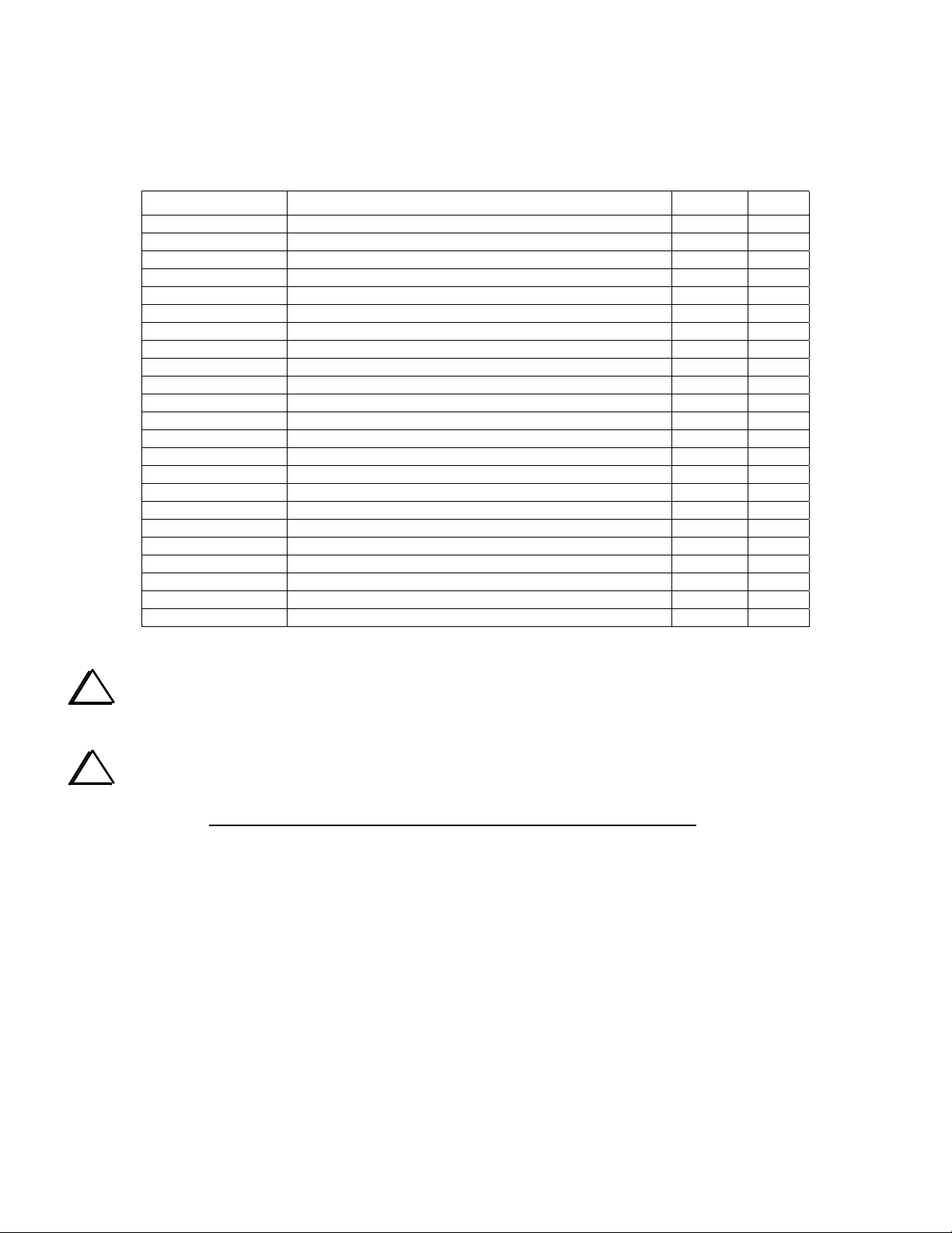
MC145170
(bottom view)
Pin 16
MC145170
(bottom view)
C90
Figure 1
X
C90
Figure 2
RFC15
Make sure C70 and C71 (VCO area) have the shortest
possible leads.
Solder a 68-pF capacitor (RF-C
RF board, between pins 13 and 12 of the MC145170,
U4 (see Figure 1). Keep the lead length short.
Add an RF choke in series with U4 pin 16. First locate
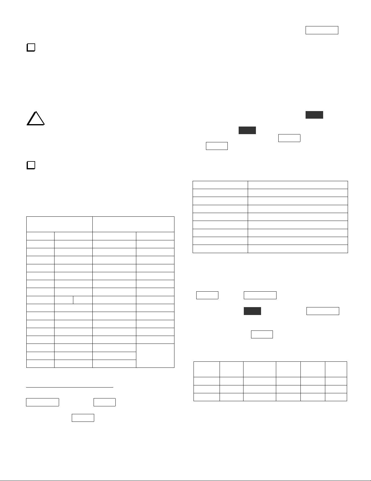
point "X" in Figure 2. Cut the indicated small trace
segment between pin 16 of U4 and capacitor C89 (on
the top side). Next, solder a miniature 100-µH RF choke
(RFC15) across the cut as shown in Figure 3. Finally,
solder a.001-µF capacitor (C91) from pin 16 to ground.
Remove C70 (4.7 pF).
5
Due to differences in the way old and new firmware did
CAL PLL.
PLL) on the bottom of the
5
C91
C90
Figure 3
Page 6

3. Misc. RF Board Changes
This step describes all RF board changes not covered
elsewhere. Parts can be found in K2ATOBKT.
Turn the K2 off. Touch an unpainted, grounded
metal surface. Remove the top cover.
Remove all options plugged into the RF board.
Remove the two screws holding the Control board
to the Front Panel board. Unplug the KAF2 if present.
Remove the Front Panel assembly (there is no
need to separate the panel from the PC board).
Remove the bottom cover.
Remove the rear panel/heatsink. Save all of the
PA hardware, including the thermal pads.
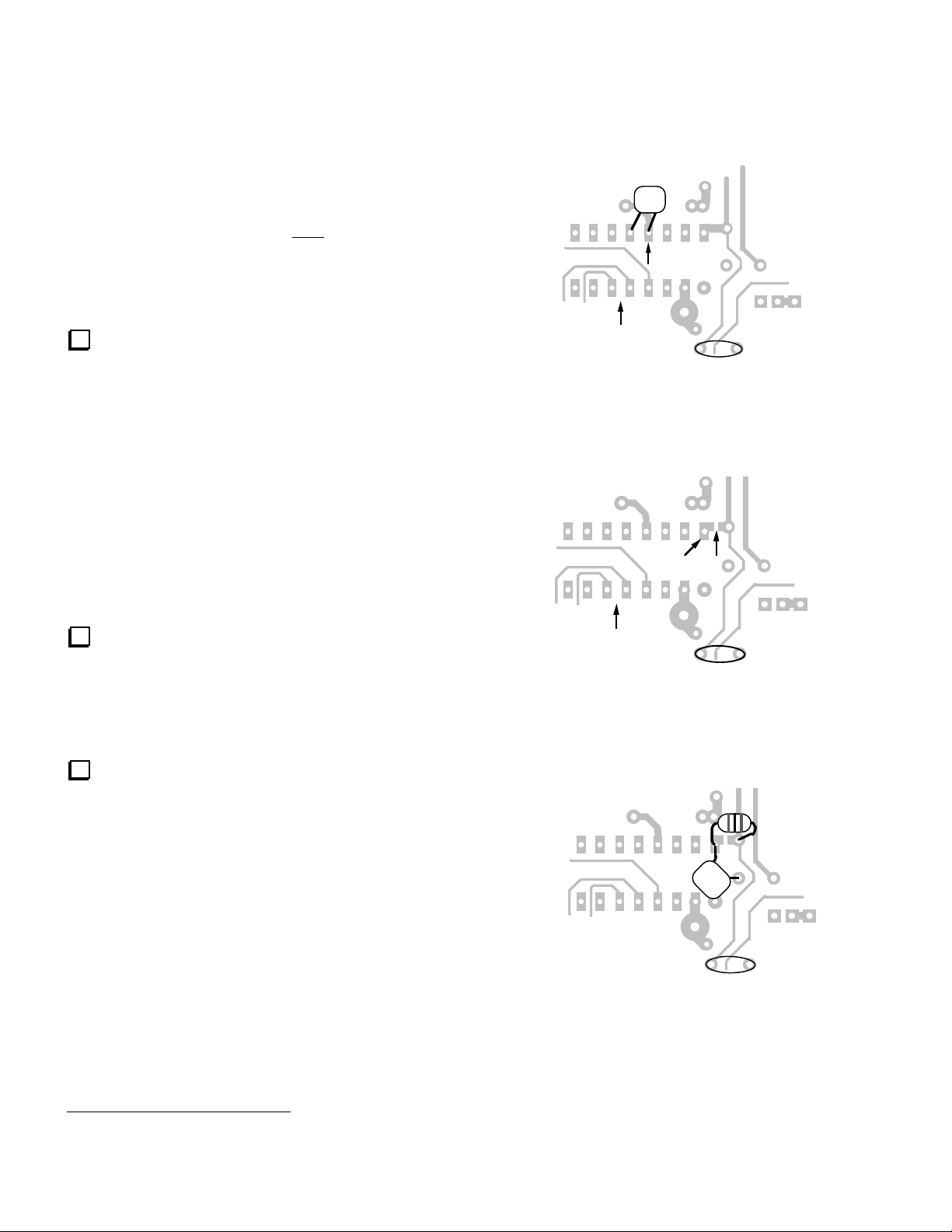
Add CRF (.047, "473") on the bottom of the RF
board as shown in Figure 4. One trace cut is required.
(This capacitor is important if you have a KBT2
internal battery or KPA100 module. It prevents
damage to the K2's low-pass filter relays in the event
that the AUX RF and AUX DC cables are reversed. On
the Rev. B RF board, the capacitor is C224.)
J3
J4
Revision XC and older Rev. C K2s Only
The following steps apply to Rev. XC and some Rev.
A K2s (prior to s/n 2000). Check the components to
see if you already have the correct values installed.
Change C68 (VCO area) from 4.7 or 5 pF to 10
pF. (Eliminates possible VCO problem on 160 meters.)
Change R1 and R2 (near the key jack) from 470
ohms (or 1k) to 220 ohms. (Lowers the voltage seen by
the K2 when a paddle is closed. With 1 k, noise
immunity may be inadequate. The microcontroller's
internal pull-up resistors can pull these lines up too
close to the "0" logic threshold.)
Change R50 from 1/4 watt to 1/2 watt (1.5 ohms,
brown-green-gold). (1/4 watt in the driver emitter was
too low to ensure adequate heat dissipation.)
Note: Other minor (preventative) design changes were made
from revision XC to revision A. Except in rare cases, they
will not significantly affect performance, and we
recommend that they not be changed. These include: L31
from 12 to 10 µH (PLL reference), C153 from 39 to 68 pF
(TX mixer coupling), C162 from .01 to .047 (post-mixer
amp), D9 from 1N34A to 1N5711 and R68 from 237 to 226
(RF detector).
Crf
K9
P6
Cut
K10
Figure 4
Change D10, at the right edge of the RF board,
from an SB530 to a 95SQ015. (The latter is an ultralow-drop diode, having a drop of only about 0.1 to 0.2
volts. This reduces wasted power in the diode on
transmit, nearly eliminates the discrepancy between
external voltmeters and the K2's internal voltage
display, and allows the use of a slightly lower voltage
supply for recharging the KBT2 internal battery.)
Re-installing the Heat Sink
Note: Skip these two steps for now if you plan to make
the bandpass filter changes on the next page.
Revision A and XC K2
Change R64 (center of the board, near U1) from
470 to 100 ohms. (Improves auxBus noise immunity.)
Change RFC11 from an RF choke to an FT37-43
toroid with 20 turns #26 enamel. Mount RFC11 on the
bottom of the board with short leads. (Reduces
unwanted S-meter activation, esp. on 17 meters.)
6
Inspect the thermal pads for Q7 and Q8. Brush
away any aluminum fragments which might have
become stuck to the pads.
Re-install the rear panel/heat sink and PA
hardware as described in the K2 owner's manual
(Assembly, Part III).
Page 7

4. 15/17 m & 20/30 m Bandpass Filters
See descriptions below. Band-pass filter realignment
will be done following all hardware and firmware
updates.
15/17 m Bandpass Filter
These optional changes narrow the 15/17 m bandpass
filter to improve image rejection. In Europe in
particular, strong shortwave broadcast stations in the
16 MHz range may produce low-level image responses
in the 15-m band with the original filter values.
Change C30 and C36 from 330 to 470 pF ("471").
Change C33 from 3 (or 3.3) pF to 2 (or 2.2) pF.
20/30 m Bandpass Filter
This optional change adds 12-pF capacitors in parallel
with each of the 20/30-m bandpass filter trim caps,
which should eliminate any difficulty in aligning the
bandpass filter on 20 meters. Some builders found that
the 20-meter trimmers "topped out" before the peak
was located.
Solder 12 pF capacitors across C21 and C23, on
the bottom of the board in the bandpass filter area.
(These capacitors are designated C28 and C29 on the
Rev. B RF board.)
Re-installing the Heat Sink
Inspect the PA thermal pads and re-install the heat sink
as described in the last two steps on page 6.
If you have an older K2 (Rev. A or XC), you may
have installed a large capacitor (150 pF or larger) at
C174 due to inadequate BFO range. Increasing only
the size of C174, without a proportional increase in
C173, may cause excessive BFO injection and is no
longer recommended. Restore C174 to its original
value if applicable (82 pF; supplied with
K2ATOBKT.)
Note: The crystals supplied with BFOMDKT should
have adequate range with the standard capacitor value
at C174 (82 pF). If the range is found to be slightly
low, two supplemental capacitors (47 pF and 120 pF),
which are supplied with BFOMDKT, can safely be
added in parallel with C174 and C173. This is
explained on page 12 as part of the BFO range test.
If you have an older K2 (Rev. A or XC), you
may have a 100 k RPACK at RP2. In this case, solder
10 k resistors (
pins 3-4, on the bottom of the board in the VCO area.
(There's no need to remove RP2, which can be
difficult. The two paralleled resistors will suffice.)
Locate the instructions supplied with BFOMDKT.
Put an "X" by the instructions covering installation of
firmware, as well as BFO and PLL test and alignment.
These steps will be skipped for now.
Follow all instructions supplied with part #
BFOMDKT, except those you marked with an "X"
above.
RREFA, RREFB) across RP2 pins 1-2 and
5A. PLL Upgrade
5. BFO Temperature Stability
This optional set of modifications reduces BFO
frequency drift an average of 70-80%. The parts and
documentation for the change are supplied with part #
BFOMDKT.
If you previously installed this mod kit, make sure
that R19 (soldered to the bottom of the board in the
PLL reference oscillator area) is 2.7 k. Some early
BFOMDKT kits were sent out with 220 ohms for use
at R19, which can cause PLL reference oscillator
instability. (1.8 to 3.3 k can be used.)
Note: Skip to step 5A, at right (PLL Upgrade) if
you've already installed BFOMDKT.
7
The PLL Upgrade is a very important design change
that was recently added to the K2 (s/n 3446 and later).
It uses a thermistor to temperature-compensate the PLL
reference oscillator, reducing drift by a factor of 5 to
10. This upgrade kit should only be installed if you
have also made the BFO mod described above. The
parts, small PC board, and documentation for this
upgrade are supplied with part # E850138.
Follow all instructions supplied with the PLL
Upgrade kit, E850138, except those dealing with
alignment and test. This will be done later.
Page 8

6. VFO ALC & 10/12 m Bandpass Filter
This set of modifications enhances the VFO ALC
circuit and narrows the 10/12 m filter. Without the
mods, a small increase in VFO spurious output will
sometimes occur when switching bands to or from 10
meters. This is usually significant only if the K2 is
driving a KPA100 or other amplifier, but we
recommend making the changes in all cases. The parts
and documentation for this mod are supplied with part
# E850093.
Follow all instructions supplied with the VFO
ALC mod kit, E850093, except 10/12 meter bandpass
filter alignment. Alignment will be done later.
If you have a rev. XC K2, you must also add R18
(1 M) to the VFO ALC circuit. Solder R18 on the
bottom of the board, directly across the pads of C59.
7. Second Crystal Filter Flatness
This change flattens the K2's second crystal filter
response, and allows the I.F. adjustment, L34, to be set
optimally for both CW and SSB. As a result, a much
better pitch match can be obtained on LSB and USB.
The parts and documentation for this mod are supplied
with part # XFILMDKT.
i
In the following step, be careful not to
overheat the crystals. Use a temperature-controlled
iron, and limit soldering time to about 3 seconds per
soldering attempt.
There are two ground pads each for X7-X11, one
on either side. Use bare wires (10 total) for grounding
the crystals, but do not solder the wires to the tops of
the crystals. The wires must be soldered to the sides,
instead, about 1/4" (6 mm) up from the surface of the
PC board.
9. AF GAIN Control Smoothness
The original "2-wire" AF gain potentiometer circuit is
susceptible to mechanical potentiometer noise at the
counter-clockwise end of its rotation. The "3-wire"
modification used in the Rev. B K2 completely
eliminates this problem, making AF GAIN adjustment
smooth. The modification also allows the AF GAIN
pot to completely turn off the audio when rotated fully
counter-clockwise. In some cases, the old circuit would
permit some residual signal to circumvent the
potentiometer in this position.
This change is optional but recommended.
Follow all instructions supplied with
XFILMDKT, except those instructions dealing with
I.F. alignment, which will be done later.
8. First Crystal Filter Grounding
The instructions for grounding the crystals in the 5pole first CW crystal filter (X7-X11) originally called
for the wires to be soldered to the tops of the cans. A
few builders subsequently determined that soldering
the ground wires closer to the base of the cans resulted
in better ultimate attenuation. Some builders also
experimented with additional bypassing of filter
control lines using surface-mount capacitors, but this
appears to offer very little additional benefit, if any.
This change is optional. Most K2 builders who used
top-grounding of the crystals in the first crystal filter
found the ultimate attenuation to be completely
satisfactory.
Follow all instructions in the application note,
except those dealing with testing the new circuit, which
will be done later. The application note can be found
at:
http://www.elecraft.com/Apps/K2_AF_pot/K2_AF_gai
n_app_note.htm (HTML)
or:
http://www.elecraft.com/Apps/K2_AF_pot/K2_AF_gai
n_app_note.pdf (PDF)
8
Page 9

10. Misc. Control Board Changes
These changes improve various operating
characteristics of the K2, as explained in each of the
steps below. The parts for these changes are included
in K2ATOBKT.
Change R6 from 470 to 100 ohms (brown-black-
brown). (Improves auxBus noise immunity.)
Change R7 from 1.96 to 1.78k (brown-violetgray-brown). (Improves current measurement
accuracy.)
Sidetone Modification
These optional changes provide a more pleasantsounding sidetone.
Locate capacitor C24 (.0027 µF), which is on the
right side of the Control board between RP7 and RP3.
As shown in Figure 6, cut the trace on the top side of
the board between C24 and pin 6 of RP7. On the
bottom side of the board, solder a 47 k resistor (yellowviolet-orange) between these two pads. (Reduces
digital switching noise in the sidetone; designated R11
on the Rev. B Control board.)
Change C12 from .001 to .0027 µF ("272").
(Improves auxBus noise immunity.)
Change C42 from .01 to 0.1 µF ("104").
(Stabilizes voltage display.)
Locate the trace on the top side of the board that
runs directly between resistors R8 and R9 (Figure 5).
Cut the trace. On the bottom side of the board, solder
an 820-ohm resistor (gray-red-brown) between the two
vias. You'll need to pre-trim the resistor's leads since it
isn't possible to cut the lead that falls between R8 and
R9. (Protects the microcontroller in the event that an
RS232 signal is accidentally connected to the
VRFDET line via the KIO2's or KPA100's AUX I/O
connector. Designated R12 on the Rev. B Control
board.)
R8 R9
R12 (on back)
Cut
R11 (on back)
RP7
C24
RP7
C24
Cut
Figure 6
Locate RP5, the 10-pin, 470-ohm RPACK at the
right side of the board. Solder an 82-mH shielded
inductor ("823") on the bottom of the Control board
between pins 7 and 10 of RP5. The leads of the
inductor should be formed such that the body can be
folded down flat against the PC board. (Designated L1
on the Rev. B board. Creates a low-frequency resonant
tank in conjunction with C33, greatly attenuating
harmonics of the sidetone. The resonant frequency is
approximately 400 Hz, but the Q is quite low, so
sidetone frequencies from 400-800 can still be used
effectively.)
RS-232 and Sidetone Source (KIO2/KPA100)
Figure 5
If you have an older K2 (Rev XC or A), C31 may
be 0.1 µF ("104"). Change C31 to .047 µF ("473").
(Improves CW keying envelope shape.)
9
If either a KIO2 or KPA100 option is installed in the
Rev. A or XC K2, the builder must make a few
additional changes to the Control board. These changes
are fully documented in the KIO2 and KPA100
manuals. (The sidetone generation is re-routed from
pin 25 of the microcontroller, U6, to pin 4 of the quad
D-to-A converter, U8. This allows pin 25 of U6 to be
used for full-duplex RS232 communications.)
There is no need to make these changes until you add a
KIO2 or KPA100. In a later step, you'll set up your
K2's configuration based on whether or not you have at
some point installed either of these options.
Page 10

AGC Threshold Control
R1 on the Control board sets the AGC threshold, which
also establishes the K2's I.F. gain. On Rev. A and Rev.
XC Control boards, R1 is fixed. A small number of K2
owners found that reducing the size of R1 slightly
could optimize the AGC threshold setting and/or bring
up the I.F. gain, so we used a trimmer at R1 on the
Rev. B board.
12. Alignment and Test
Re-Installation of Boards and Panels
Reinstall the front panel assembly.
Reinstall the Control board (and KAF2 option if
applicable). Secure the Control board to the Front
Panel board using the provided hardware.
We don't recommend replacing R1 with a trimmer on
older K2s, for two reasons: the number of K2s that
would benefit from it is quite small; and adding a
potentiometer here is difficult because R1 is very close
to the side panel.
After you've completed all hardware changes and have
the K2 reassembled, you can test your AGC threshold
to determine if a change in the value of R1 is
warranted. This is covered in on page 14.
11. Firmware Installation
If you determined earlier (page 3) that your
firmware must be replaced, complete the following
steps. Otherwise skip to Alignment and Test (right
column).
Touch an unpainted, grounded metal surface.
Remove the old K2 firmware, U6 (Control board),
using a small screwdriver to pry it gently out of its
socket at both ends. Store it in a safe place.
Straighten the leads of the new microcontroller
(PIC18C452).
Install the new microcontroller. Orient the
notched or dimpled end of the IC with the notched end
of its component outline.
If your I/O controller (IOC) firmware is revision
is 1.05 or earlier, or if you were sent a new I/O
controller by Elecraft (PIC16F872), remove U1 on the
RF board. Store it in a safe place. Install the
replacement IOC at U1.
Reinstall the bottom cover.
Reinstall all options that plug into the RF board.
Reinstall the rear panel/heatsink if you have not
done so already (last two steps on page 7).
Firmware Configuration
Turn on the K2. You may see I N F O 2 0 1 (for
about 11 seconds) if you have installed new firmware.
The sidetone may not be working at this point, and the
filters and S-meter may not be calibrated.
If you saw I N F O 2 0 1 , you must re-enter all of
your menu and CAL parameters as explained in the
following steps. If you didn't see INFO 201, skip to
Supplemental Menu Parameters (next page).
Set up all primary menu entries using data
recorded in Table 2 (page 3). S T L and S T P must
be set up, even though you may not have any sidetone
at this point. This will be corrected later.
If your old firmware was older than revision 2.00,
please read the "K2 Revision 2 Firmware" manual,
which you should have received with the new firmware
(you can also download it from our web site). This will
explain what the secondary menu entries are used for,
and how to access this menu.
Set up all secondary menu entries from Table 2.
If you have the K60XV option installed (60 meter
adapter), set the D 1 9 secondary menu entry to Y (see
K60XV manual). Otherwise leave D 1 9 set to N .
Set up the C A L C U R , C A L S L O , and C A L
S H I entries from Table 3. C A L T P A is stored by
the microcontroller in the KPA100, if applicable, and
does not need to be set up here. C A L P L L will be
done later.
10
If applicable, set up transverter bands (Table 4).
Set up the filter bandwidths (but not the BFOs)
for each mode using data from Table 5. The BFOs will
be set up after the BFO range check.
Page 11

Supplemental Menu Parameters
The D I S P L A Y
parameters when editing certain menu entries. Set up
these parameters as follows:
Test your sidetone using the S T L menu entry. If
the sidetone is missing,
then tap D I S P L A Y
The default is U 8 - 4 , compatible with the Control
board modifications required for the KPA100 and
KIO2. If you have never installed a KIO2 or KPA100,
the source should be set to U 6 - 2 5 .
"8R Hold" mode keeps the 8R (8 volts receive)
line low between CW elements. This is now the default
mode for 8R; it eliminates excessive T-R relay
switching when the K2 is used with transverters or
amplifiers. At present we don't know of any reason to
set the 8R mode to "normal," where 8R is allowed to
go back to 8 volts between CW elements. However, if
you wish to select this mode, locate the T - R menu
E D I T its parameter, and tap D I S P L A Y .
entry,
You'll see 8 R n o r on the LCD.
switch is used to access additional
E D I T the S T L parameter,
to change the sidetone source.
PLL Reference Oscillator Range Test
This test is necessary if you made the Temperature
Stability modifications or changed any other
components in the PLL reference oscillator.
Make sure the bottom cover is securely attached,
and that the K2 has been turned on for at least 5
minutes (operating at room temperature).
Plug the frequency counter probe into P6 (Control
board).
Connect the probe tip to the PLL reference
oscillator test point, TP3 (left-front corner of the RF
board, near U4). Note: If an audio filter module is
installed, you'll need to remove it to get to TP3.
Using the menu, select C A L F C T R , then hold
E D I T a second time to enable the frequency counter.
The counter should show a frequency of 1 2 0 9 0 kHz
+/- 30 kHz. If it is 0000.00, changing rapidly, or out of
range, you could have a problem with the counter
probe or the PLL Reference Oscillator.
"Auto-detect" allows you to connect a keyer,
computer, or hand key to the K2 along with a keyer
paddle. Auto-detect is normally on. To turn it off,
locate the I N P menu entry,
tap D I S P L A Y . You'll see A D E T O F F .
The default fan mode for the KPA100 option is
F A N n o r . If you prefer F A N L o H i or F A N H i ,
locate the P A entry in the secondary menu,
parameter, and tap D I S P L A Y to select the desired
mode.
E D I T its parameter, and
E D I T the
When you’re in frequency counter mode, the
B A N D +
the range of the PLL reference oscillator. First, tap
B A N D +
space below (typically about 12097-12100 kHz). Then
tap B A N D - and write down this frequency reading
(typically 12085-12092 kHz).
Ref. High Freq. Ref. Low Freq. Range (kHz)
____________ ____________ __________
higher reading. The range must be between 9.0 and 15
kHz (if not, you may have a problem in the PLL
reference oscillator, most likely with one of the
components recently installed). Tap M E N U
C A L F C T R .
and B A N D - switches can be used to check
and write down the frequency reading in the
Subtract the lower frequency reading from the
to exit
If you removed an audio filter option temporarily
to get to test point TP3, reinstall it now.
11
Page 12

BFO Test
The BFO will be tested in the following steps. You
should do this test even if you did not make the
Temperature Stability modifications.
Make sure the bottom cover is securely attached.
Switch to the 40-m band.
Connect the frequency counter to the BFO test
point (TP2), which is on the right side of the RF board
near the crystal filter.
Using the menu, activate C A L F C T R . The
counter should show a frequency between 4908 and
4918 kHz.
If your BFO range is slightly less than 3.6 kHz,
and/or the low frequency is higher than 4912.7, your
BFO crystals probably have higher than average Q.
You can safely compensate for this by increasing the
size of C174 and C173 in the BFO circuit. The
Temperature Stability mod kit (BFOMDKT) includes
two capacitors for this purpose, 47 pF to parallel with
C174, and 120 pF to parallel with C173. If you didn't
order this mod kit, you can use any temperature-stable
capacitors (NPO, C0G, or N750 types) in the following
ranges: 39-68 pF (in parallel with C174), and 100-180
pF (in parallel with C173).
If the BFO doesn't appear to be working, or its
frequency range is shifted too high or too low, it may
be due to one of the following:
i
If you see a reading of 0 0 0 0 . 0 0 kHz or one
that is changing rapidly, you may not have the
frequency counter probe connected properly. Also
inspect the leads of L33 carefully. They could be
broken or poorly soldered.
When you’re in frequency counter mode, the
B A N D +
the range of the BFO. First, tap B A N D +
and B A N D - switches can be used to check
and write
down the frequency reading below (typically about
4916-4917 kHz). Then tap B A N D -
and write down
this frequency reading (usually about 4911-4913 kHz).
Finally, calculate the BFO range (high - low) in kHz.
Typical range is 4 to 5 kHz.
BFO High Freq. ___________
(must be 4916.3 kHz or higher)
BFO Low Freq. ___________
(must be 4912.7 kHz or lower)
Range (High - Low) ___________
(must be 3.6 kHz or more)
If you didn't calibrate the K2's internal frequency
counter using an external counter, it may not be reading
accurately. If possible, borrow an accurate counter and
re-do the 4 MHz Oscillator Calibration as described in
the K2 owner's manual.
If you installed the new BFO toroid at L33 (T44-7),
look closely at its leads using a magnifying glass. The
wire used is very small, and easily broken during
installation.
One or more of the capacitors in the BFO circuit could
be of the wrong value.
BFO Alignment
The following two steps will be necessary if you saw
I N F O 2 0 1 on the display following firmware
installation, or if you made the Temperature Stability
modifications to the BFO.
Make sure the bottom cover is securely attached.
Set up the BFOs for all modes and filters using
the frequencies from Table 5 (page 4). You'll have a
chance later on to fine-tune the BFO settings.
12
Page 13

VFO Linearization
I.F. Amplifier Alignment
This procedure will be necessary if you installed new
firmware or if you installed the PLL Upgrade (or made
other changes in the PLL area of the RF board). The
procedure will be done only on 40 meters. It should
not be repeated on each band.
Allow the K2 to warm up at normal operating
room temperature for at least five minutes. The
bottom cover must be installed.
Plug the K2 frequency counter cable into P6 on
the Control board. Connect the probe end to test point
TP1 on the RF board (VCO, center-left side of the RF
board).
Switch to 40 meters and set the VFO to about
7100 kHz.
Tap M E N U and locate the C A L entry. Hold
E D I T , then change the parameter to P L L . Hold
E D I T again to begin the calibration procedure. You'll
see a frequency in the 12 MHz range displayed, and the
letter "d " will flash as the firmware records calibration
data. After approximately 5-10 minutes, you'll hear a
short tone, and E N D will be displayed. Tap any switch
to clear this message.
If you made the recommended modification to the
second crystal filter, L34 will need readjustment. L34,
located near the right front corner of the RF board, is
used to peak the output of the I.F. amplifier.
Using the wide end of the plastic tuning tool,
adjust the slug in L34 until it is near the top of the can.
Stop turning the slug when it appears to be at the
top or when you feel resistance.
Turn L34’s slug one full turn clockwise (down
into the can).
Set the band to 40 meters using B A N D + or
B A N D -
nominal bandwidth).
clockwise (max. gain). Disconnect the antenna from
J4, if one was connected.
turns on.
the front panel jack, and turn the AF GAIN control to
about midway.
. Select CW Normal and FL2 (700 Hz
Make sure the RF GAIN control is fully
Tap P R E / A T T N until the PRE annunciator
Connect a pair of headphones (stereo or mono) to
i
If you see I N F O 2 3 2 at any time during
VFO calibration, verify that you were on 40 m, with
the counter cable at TP1.
You can check the VFO's accuracy using a signal
at a known frequency (see page 98 of the revision C
K2 manual). Note: In the Revision C manual, steps 8
and 11 on page 98 are incorrect for the new firmware.
C A L P L L is now run only once, and only on 40 m.
Move the K2 counter cable to the BFO test point,
TP2.
Slowly tune the VFO to locate the weak
internally-generated signal near 7000 kHz.
While listening to the signal at 7000 kHz, adjust
L34 for best signal strength and lowest noise. This
setting occurs at about 1 to 1.5 turns below the top of
the can. (You can use your DMM on AC volts, at the
speaker jack, to obtain a more sensitive indication.)
13
Page 14

Receiver Pre-Alignment, 10-30 meters
Transmitter Alignment, 10-30 Meters
This step is necessary if you made any changes to the
10-30 m band-pass filters (steps 4, and 6, page 8). If
you didn't make these changes, continue with FineTuning Filter Settings, page 15.
Switch to 20 meters and set the VFO for about
14100 kHz.
Turn on the RF preamp by tapping P R E / A T T N
until you see the PRE annunciator turn on.
Use a signal generator or an antenna to inject a
signal or noise at this frequency.
i
Since some inductors are shared between two
bands, you must always align the bands in the order
indicated. Always use this procedure if you re-align the
filters later.
Set C21 and C23 to their mid-points. Adjust L8
and L9 for maximum signal strength. (This step presets C21, C23, L8, and L9 before final adjustment in
the next two steps.)
Note: When switching to each of the remaining bands
to be aligned, you'll need to inject a signal or use an
antenna.
Switch to 30 meters (10100 kHz) and turn on the
preamp. Adjust L8 and L9 for maximum signal
strength.
Switch back to 20 meters (14100 kHz). Adjust
C21 and C23 for maximum signal strength.
Switch to 15 meters (21100 kHz) and turn on the
preamp. Adjust L10 and L11 for maximum signal
strength.
Switch to 17 meters (18100 kHz) and turn on the
preamp. Adjust C32 and C34 for maximum signal
strength.
Switch to 10 meters (28200 kHz) and turn on the
preamp. Adjust L12 and L13 for maximum signal
strength.
Switch to 12 meters (24900 kHz) and turn on the
preamp. Adjust C44 and C46 for maximum signal
strength.
Set the POWER control for 2.0 watts. Connect a
dummy load at the antenna jack.
Switch to 30 meters. Adjust L8 and L9 for
maximum power output in TUNE mode. Avoiding
using TUNE mode for more than 5 seconds at a time.
Switch to 20 meters (14100 kHz) and adjust C21
and C23 for maximum power output.
Switch to 15 meters (21100 kHz) and adjust L10
and L11 for maximum power output.
Switch to 17 meters (18100 kHz) and adjust C32
and C34 for maximum power output.
Switch to 10 meters (28200 kHz) and adjust L12
and L13 for maximum power output.
Switch to 12 meters (24900 kHz) and adjust C44
and C46 for maximum power output.
AGC Threshold Test
A few K2 builders found that their overall receive gain
was too low because of a less-than-ideal AGC
threshold setting. If you think you might benefit from a
change in this threshold, follow the steps below.
Otherwise, skip to the next page.
Connect an antenna to the K2, and switch to a
quiet band (one with little atmospheric noise). Turn
AGC off by holding the P R E / A T T N
switches together.
If the level of background noise increases
significantly with AGC off, even on a quiet band, you
may benefit from an adjustment to the AGC threshold.
Remove the Control board and temporarily substitute a
potentiometer for R1, presetting it to R1's fixed value.
Once you find a value of R1 that brings I.F. gain up
slightly while not compromising AGC performance on
large signals, you can install a fixed resistor of that
value.
If you did make a change to R1's value, you'll
need to recalibrate C A L S H I and C A L S L O
(owner's manual, page 84).
and A G C
14
Page 15

Fine-Tuning Filter Settings
13. Speaker grille cloth
You can optionally fine-tune your BFO settings
for each mode by ear or by using a computer-based
tool such as Spectrogram.
If you have the KSB2 option (SSB adapter), and
you made the recommended changes to the second
crystal filter, you may wish to fine-tune the LSB and
USB BFO settings so that the filters have the same
noise pitch.
Note: Only the SSB BFO settings for FL2, 3, and 4
should be made in receive mode. The SSB BFO
settings for FL1 should be made in transmit mode,
either listening to your signal locally or having a
nearby station listen for you. This is because FL1 is
always used in transmit mode (and for receive, when
selected), whereas FL2-4 are only used in receive
mode. FL2-4 can be set up differently without affecting
your transmitted signal. Refer to the KSB2 manual for
more details.
AF GAIN Potentiometer Test
The following two steps apply if you made the AF
GAIN potentiometer smoothness modification.
Grille cloth (part #E850089) can optionally be added to
your original K2 top cover. (The KPA100 module
already has grille cloth for its speaker.)
Remove the speaker from the top cover. This may
involve removing the battery option (KBT2) or other
top-cover options. If you do have to remove a battery,
be sure to turn the battery switch OFF using the rearpanel slide switch. Also, disconnect both leads from
the battery terminals and cover the terminals with tape
to prevent accidental shorts.
Trim the supplied grille cloth to the size of the
speaker frame.
Place the #4 fibre washers (black) at each of the
top cover's four speaker mounting holes. Trim the
corners of the grille cloth so it just fits between the
fibre washers, not touching them.
Place the speaker on top of the fibre washers and
grille cloth. Secure it with four 3/8" (9.5 mm) screws,
#4 lock washers, and 4-40 nuts. Do not over-tighten the
nuts.
Re-install the top cover or KPA100 module.
Rotate the AF GAIN control slowly, near the
counter-clockwise end of its rotation, while listening to
a steady carrier (e.g., the internally-generated signal at
4.000 MHz). There should be no noticeable noise
(crackles, etc.) as you rotate the control.
Set the AF GAIN control to its fully counterclockwise position (minimum gain). You should hear
complete silence, with no audio signal leak-through.
15
 Loading...