

Page 1

ELECRAFT K160RX 160 METER MODULE
WITH RECEIVE ANTENNA SWITCH
Assembly and Operating Instructions
Revision D, Oct. 10, 2006. Copyright © 2000, 2006, Elecraft; All Rights Reserved
Introduction
The K160RX adds the 160-m band and a receive antenna switch to the Elecraft K2. The antenna switch
functions on all bands, but is especially useful on 160 m where a low-noise receive antenna is often used.
Preamp and attenuator settings used with the receive antenna are saved on each band (see pg. 10).
The K160RX plugs directly into the K2's RF board, and requires no wiring other than a short lead to the
receive antenna jack. Once the module is installed, the 160-meter band will become available using
BAND+ and BAND- or via direct frequency entry. Also, the RANT menu entry (receive antenna) will be
activated.
Latching relays are used for both the 160-meter low-pass filter and the receive antenna switch. These
relays consume no power except when actually being switched on or off, so the K160RX module does not
increase the current drain of the K2. Please refer to the schematic diagram at the end of the manual for
circuit details.
Specifications
160 m Frequency Range 1.8 to 2.0 MHz
Power Output 10 watts (nominal), adjustable to below 0.5 W
Receive Antenna Switch
Impedance 50 ohms
Isolation > 50 dB between RX ant. jack and main antenna jack (J4)
Applicability All bands (independent selection on each band)
Current Drain 0 mA
Size 2.6 x 0.8" (6.6 x 2 cm)
1
The VFO will typically tune down to about 1.4 MHz. This extended receive coverage is useful for
receiving stations in the high end of the A.M. radio band, although the band-pass filter will significantly
attenuate signals below 1.8 MHz.
1
Page 2
Parts Inventory
The table below lists all parts in the kit. If you have trouble identifying any of these items, consult the
K2 Owner's manual, which has photographs of similar parts.
Ref. Description Part # Qty.
Components on K160RX Module
C4,C5,C6 Capacitor, .001 µF disc or monolithic (“102”) E530001 3
C1,C3 Capacitor, 1500 pF NPO or C0G, monolithic (“152”) E530002 2
C2 Capacitor, 2700 pF NPO or C0G, monolithic (“272”) E530003 1
K1,K2 DPDT latching relay, 5 V (“G6HU-2”) E640001 2
L1,L2 Toroidal inductor, approx. 5 µH, 21 turns on T44-1 or T50-1
core (blue). (Either a T50-1 or T44-1 core can be used with the
same no. of turns.)
P1 Conn., 16 pin male, 0.1" spcg., gold E620002 1
MISC #26 enamel wire E760002 3 ft.
MISC #24, Wire, Insulated, Stranded E760001 6 in.
MISC PC Board, K160RX E100088 1
Components on RF Board
C68 Capacitor, 10 pF NPO disc E530006 1
C153 Capacitor, 68 pF NPO disc E530007 1
C75 Capacitor, 470 pF NPO disc or monolithic (“471”) E530004 1
C13,C14 Capacitor, 1200 pF NPO disc or monolithic (“122”) E530005 2
J14 Conn., 16 pin female, 0.1" spcg., gold E620003 1
Hardware andMiscellaneous
K160-J1 Panel-mount BNC connector E620001 1
HDWR #4 split lock washer (includes 3 spares) E700004 8
HDWR 4-40 x 1/4" ZN ST phillips machine screw E700005 2
E680001 2
HDWR 3/16" dia. x 5/8" long round 4-40 threaded standoff E700003 1
2
Page 3
Assembly
i
A fine-point, temperature-controlled soldering iron is required to assemble this kit. A high-
wattage iron may damage components, pads, or traces.
i
In the following steps you'll be installing the latching relays (K1 and K2). Relay pins must not be
bent or trimmed as this may cause unreliable mechanical operation.
Place relays K1and K2 on the top side of the 160 meter PC board (component side). One end of each
relay has a heavy line printed across the top to indicate the pin 1 end. This end must be matched with the
same end of the relay’s PC board outline. Do not solder the relays yet.
Solder only two pins on each relay, at opposite corners. Do not bend or clip relay leads.
Verify that the relays are in the correct orientation and are seated flat on the board, then solder all of
the remaining relay pins.
Install all of the capacitors (C1-C6), bending the leads out slightly on the bottom to hold them in
place. Trim the leads to about 1/16" (1.5 mm) long before soldering to insure that the leads do not come
into contact with the toroids on the main board.
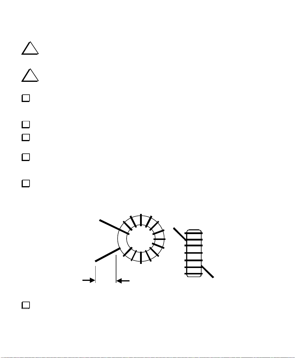
Inductor L1 is wound on a T44-1 or T50-1 toroidal core (blue) using 17 inches (43 cm) of #26 enamel
wire. To wind the inductor, “sew” the long end of the wire through the core exactly 21 times. Each pass
through the core counts as one turn. The finished winding should look very similar to the drawing below,
but with 21 turns rather than 14.
Remove insulation
Verify that the turns of L1 are not bunched together. They should occupy about 85% of the core’s
circumference as shown above.
3
Page 4
Cut L1's leads to about 1/2" (12 mm) long. Completely remove the enamel insulation from the leads
to within 1/16” (1.5 mm) of the core. To remove the insulation, use your soldering iron tip (and a little
solder), a butane lighter, or sand-paper. If you scrape the insulation off, be careful not to nick the wire.
Install L1 flat against the PC board as shown by its component outline, then pull the leads taut on the
bottom of the board. Note: The correct holes for L1's leads are both just to the right of the component
outline. Do not use the hole near the "L1" label.
Trim and solder the leads of L1. When soldering, make sure that the solder binds well to the leads. If
the lead appears to be an “island” in a small pool of solder, chances are it is not making good contact. It’s a
good idea to measure from pad to pad using an ohmmeter to be sure the leads are making contact.
Wind and install L2 in exactly the same way as L1.
Install 16-pin male connector P1 on the bottom of the PC board in the position indicated by its
component outline. Do not solder yet. The drawing below shows how P1 should appear viewed from the
left end of the board, with the notch towards you and the component side up.
Componen ts on top
P1 (onbo ttom)
Solder just one pin of P1, near the middle of the connector (close to relay K1 on the top side of the
board). Be careful not to touch K1's plastic case with the soldering iron.
Verify that P1 is now perpendicular to the PC board and is seated completely flat. If not, re-heat the
soldered pin and press down on all of P1's pins until the connector drops into place. Once the connector is
seated correctly, solder the remaining 15 pins.
Cut a 1.5" (3.8 cm) length of hookup wire. Remove 1/4" (6 mm) of insulation from each end.
Solder one end of this wire to the pad labeled "RX" near the notch in the 160-m PC board. The other
end will be connected to the center terminal of the receive antenna jack (K160-J1) in a later step.
Prepare a second 1.5" (3.8 cm) wire. Solder one end of this wire to the ground pad just to the left of
C5 on the 160-m PC board. This pad is not labeled. The other end will later be connected to the solder lug
of the receive antenna jack.
Inspect the 160-meter module for solder bridges or cold solder joints, especially around P1.
4
Page 5

Installation
Turn off the K2. Also set the INT BATTERY switch to OFF if applicable. Remove the top cover.
Disconnect the speaker, internal battery, or other options installed in top cover and set the cover aside.
Remove the bottom cover (6 screws).
Remove the nuts from the key jack and antenna jack. Remove the heat sink (6 screws, two nuts), being
careful to save all of the hardware.
With the K2's front panel facing you, identify the proper location of the 160-m PC board and related
hardware using the drawing below. The160-meter module will be plugged into the RF board at J14. The
receive antenna jack will be mounted on the heat sink in the final installation steps.
RX Ant. Jack
160 Meter Module
RF Board
Remove jumper W1 on the RF board, near the left end of J14. W1 should be desoldered, not clipped,
so that you can re-install it later if the 160-m module is removed.
5
Page 6

Install the 16-pin female connector on the RF board at J14 as shown by its outline, but do not solder
yet. The side view of J14, below, shows how it should appear once properly seated. This connector is
somewhat fragile because of its height. Be careful not to flexit during installation.
J14
Solder just one pin near the middle of J14, on the bottom of the RF board. Then, if the connector is not
sitting completely flat against the RF board or is not vertical, reheat this pin and carefully press the
connector down. You may hear it snap into place when you heat the pin.
Solder the remaining pins of J14.
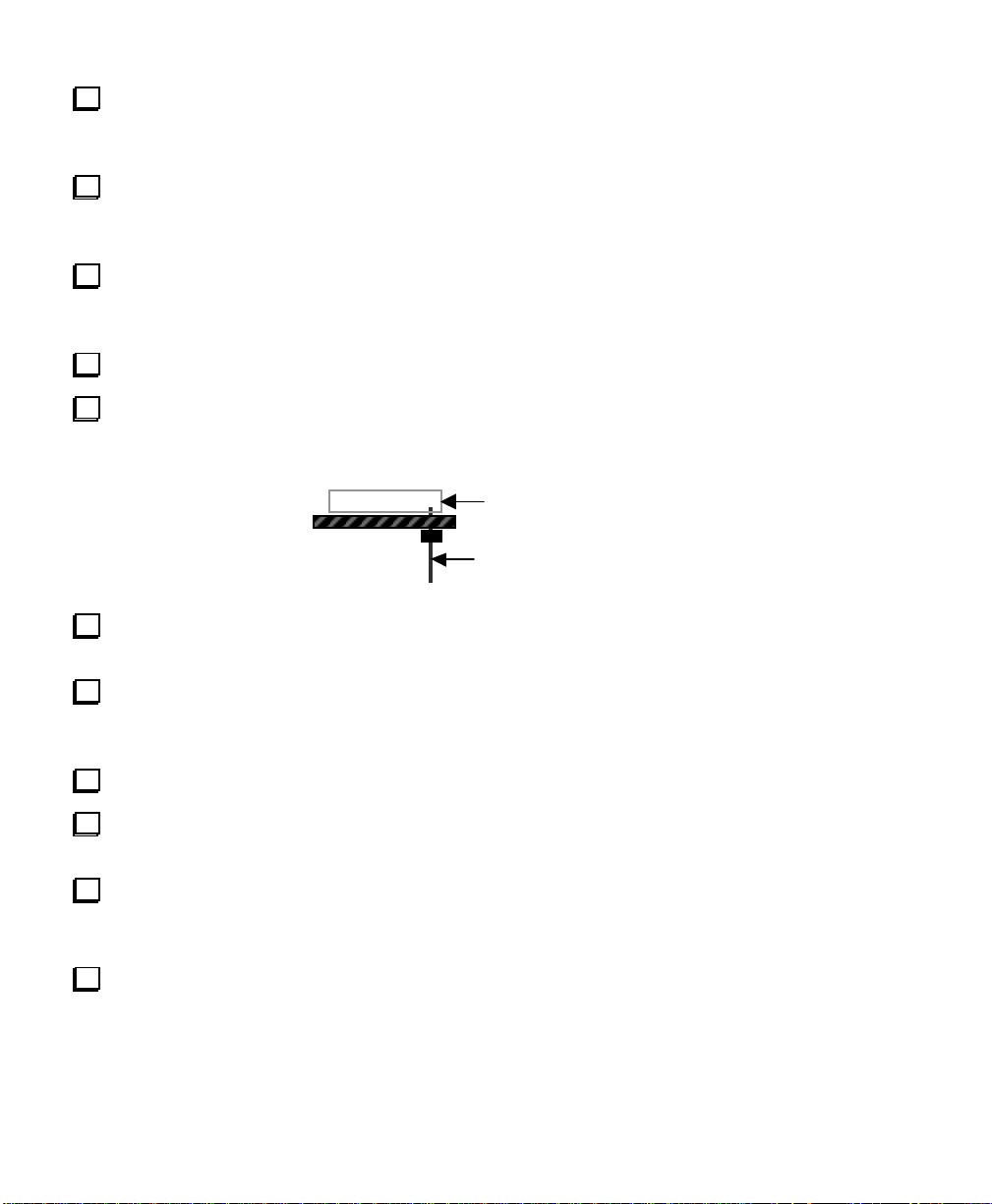
Install the 5/8" (16 mm) standoff on the top of the RF board as shown below, using two split lock
washers and a 1/4" (6 mm) machine screw. The mounting hole for the standoff is just to the left of RFC3
(near J14). You must use only one split lock washer between the standoff and the top of the RF board
in order to position the 160-m module at the correct height.
Examine the standoff and its hardware to insure that it does not touch the nearby pad of C113.
If your K2 has a 4.7 pF capacitor at C68 (near T5), replace it with the supplied 10 pF capacitor.
If your K2 has a 39 pF capacitor at C153 (near U10), replace it with the supplied 68 pF capacitor.
Install C75, which is on the left edge of the RF board near K13.
Install C13 and C14 in the band-pass filter section of the RF board, near L3 and L4.
6
Page 7

Carefully examine the hardware associated with PA transistors Q7 and Q8, including the standoffs,
shoulder washers, and thermal insulators. If any of the hardware appears to be damaged, it should be
replaced. (These items are supplied with the K2 PA Hardware Kit.)
Remove any loose metallic particles from both the inside and outside surfaces of the heat sink,
especially in the area of the thermal insulators.
Install the receive antenna jack (K160-J1) on the rear panel of the heat sink. This connector is supplied
with a nut, lock washer, and solder lug. The solder lug should be placed onto the connector first so that it
makes contact with the inside rear panel of the heat sink. Rotate the solder lug to the left (as viewed from
the front of the K2). In this position, it will not interfere with the installation of the 160-m module or the
optional KAT2 antenna tuner.
Re-install the heat sink using the method described in the K2 Owner's Manual. When replacing the
nuts on the PA transistor mounting screws, use two #4 split lock washers, even if internal-tooth lock
washers were originally used. The split lock washers will not gouge the panel. Do not over-tighten any of
the hardware.
Using a DMM on its lowest resistance scale, measure resistance from the collector of each PA
transistor (Q7, Q8) to ground. If you see a reading of less than 100 ohms, the heat sink may be shorted to
one of the transistor tabs.
Re-install the nuts on the key and antenna jacks.
Plug the 160-m module into J14, and secure it to the standoff using a 1/4" (6 mm) machine screw and
split lock washer.
Connect the 160-m module to the receive antenna jack. The wire connected to the "RX" pad on the
module should be soldered to the jack's center pin, and the other wire soldered to the jack's solder lug.
Re-install the bottom cover (6 screws).
7
Page 8

Initial Test
Connect a power supply or battery to the DC power jack, J3.
Turn on the K2 and verify that you see the usual ELECRAFT display. If no display appears, you
probably have a short from one of the PA transistors to ground, which will trip the self-resetting thermal
fuse (F1). You should turn off the K2 immediately in this case and locate the short. In most cases the short
will be due to an incorrectly-installed shoulder washer on either Q7 or Q8.
Use the BAND+ or BAND- buttons to get to the 160 meter band (1.8-2.0 MHz). If 160 meters does
not appear in the list of available bands, then the K160RX module has not been recognized by MCU
(Control board, U6). Turn off the K2, then unplug the 160-m module and check continuity on the RF board
from pin 2 of U1 to pin 16 of J14. Also verify that R65 is installed. (R65 is on the bottom of the board, near
U1, and is accessible via the bottom cover). Finally, check the resistance of the relay coils on the 160-m
module by measuring between pins 1 and 10 (pin 1 has a round pad, while the others are square). You
should see a resistance of about 250 ohms. If not, you may have the relays installed backwards.
Receive Antenna Switch Test
Note: The receive antenna switch is controlled by the menu's RANT entry, not the ANT 1/2 button on
the front panel. The ANT 1/2 button is reserved for use with the KAT2 and KAT100 automatic antenna
tuners, which include two antenna jacks.
Switch to any band other than 160 meters and connect a suitable antenna.
Tap the MENU button, then scroll to the RANT entry (receive antenna selection). The parameter
displayed should now be either OFF or ON. If you see "--", the K160RX module has not been
recognized (see above).
When the receive antenna switch is turned on, the antenna connected to the RX antenna jack is used
on receive, while the main antenna at J4 continues to be used on transmit. Test this by changing RANT to
ON. Use EDIT to select edit mode, and BAND+ / BAND- or the main tuning knob to change the
parameter. The receiver background noise should disappear when the receive antenna is ON. Then move
the antenna from the main antenna jack (J4) to the RX antenna jack. The background noise should return.
You may wish to connect antennas to both jacks and try switching between them on receive. Never
transmit without an antenna connected to J4.
The receive antenna switch can be set independently on each band. Switch to each band in turn, and
use the RANT menu entry to verify that the receive antenna is OFF. Recall that you can use EDIT to go
directly from the normal frequency display to the last menu entry used without first tapping MENU.
If you expect to switch frequently between the main and receiving antennas, you can assign the
RANT menu entry to programmable function button PF1 or PF2.This will eliminate the need to go into
the menu each time.
8
Page 9

160 Meter Alignment
Select 160 meters (1.8-2.0 MHz) using BAND+ or BAND-.
i
The following step is only necessary if your K2 firmware is older than revision 2.00. With
revision 2.00 and up, CAL PLL is done only once (on 40 m), so there's no need to do it on 160 m.
Set the VFO for 1800.10 kHz. Connect the K2's internal frequency counter to TP1 (VFO test point).
Use the menu to select CAL PLL, then hold EDIT a second time to initiate 160-meter VFO linearization.
This takes about 2 minutes, after which you should see END on the display. Note: If you see INFO 231
on the display, you have probably connected the counter to the wrong test point. If you see INFO 235,
then the PLL reference oscillator range may be inadequate for 160-meter coverage.
i
The 80 and 160 meter bands share the same basic band-pass filter components, with two additional
capacitors switched in on 160 meters (see RF board schematic, sheet 3). If you have a signal generator and
sensitive RF voltmeter or oscilloscope, you can optimize the settings of L3 and L4 in receive mode for
minimum loss on both bands. However, the transmit-based approach described below is also satisfactory.
Set the power level for about 2 watts using the POWER control. Set the VFO to 1840 kHz.
Connect a 50-ohm, 10-W (minimum) dummy load to the main antenna jack (J4). Use a wattmeter with
an analog meter movement if one is available, as this makes alignment a bit easier. Otherwise, you can use
the K2's internal wattmeter. Note: If you have an ATU installed (KAT2 or KAT100), connect the dummy
load to one of the ATU’s antenna jacks. Also put the ATU into CALP mode. This sets L and C to zero
and disables the auto-tune function so it won’t interfere with 160-m band-pass filter alignment.
Locate the 80/160 m band-pass filter inductors, L3 and L4, which are near the back-left corner of the
RF board. Hold TUNE to key the transmitter, then peak both L3 and L4 alternately for the highest power
output reading. Use only the tuning tool supplied with the K2. Note: The transmitter may already put out 2
watts even before you have adjusted L3 and L4, but you should still peak the output, which may go well
above 2 watts. The next time you hold TUNE, the K2's ALC will set the power to about 2 watts.
Repeat the previous step if necessary to be sure that L3 and L4 are peaked.
Set the POWER control for 10 watts, and make sure that the transmitter can attain this level at both
1800 and2000 kHz using TUNE. Next, switch to 80 meters and again check for full power output at both
3500 and4000 kHz. If you cannot reach full power at the high end of either or both bands, set the VFO to
1850 or 1900 kHz and re-peak L3 and L4 at 2 watts, then re-test.
Move the frequency counter cable to back to TP2 (BFO).
Turn off the K2. Re-connect the speaker, battery, etc., and install the top cover.
9
Page 10

Using the K160RX
Receive Antenna Preamp and Attenuator Settings
Preamp and attenuator settings can be different for the receive antenna. For example, if you use a lownoise, low-gain receive antenna on 160 m, you might want the preamp to be on whenever the receive
antenna is on, but off when you select the main antenna for receive. The K2 saves preamp and attenuator
settings for the receive antenna ON and OFF cases on a per-band basis.
160-Meter Frequency Selection
You can switch to 160 musing BAND+ / BAND- . To use direct frequency entry, add a leading zero (e.g.,
0 1 8 0 5). This distinguishes between the 160-meter band (1.8 MHz) and 17-meter band (18 MHz).
High Current (HI CUR) Warning
If you see a HI CUR warning when operating on 160 meters at over 5 watts, it may be due to low supply
voltage. For operation above 5 watts on 160 meters the supply voltage should be 12.0 volts or higher on
key-down (or when using TUNE). The voltage can be checked using the DISPLAY button. With
batteries and some power supplies, the voltage on transmit may drop from 13 or 14 volts to 12 volts or
lower on transmit. In this case you should reduce power to less than 10 watts.
Operating Considerations
160 meters–or "top band" as it is sometimes called–is the only Amateur band in the LF range (300 kHz-3
MHz). At these frequencies, low-power operation is particularly challenging. First of all, it can be difficult
to erect a full-size antenna. A quarter-wave vertical cut for 1825 kHz would be roughly 128 feet (44 m) tall,
and a dipole would be nearly the length of a football field. In addition, 160 meters is often plagued by
atmospheric noise, particularly in summer.
You'll probably find 160 meters most rewarding if you do the following:
1. Put up the largest possible antenna, and use a high-efficiency antenna tuner if you don’t have room for
a resonant system. The Elecraft KAT2 and KAT100 ATUs will tune most wire antennas on 160
meters. (These ATU options also include an SWR bridge, providing more accurate power readings
than the K2's internal RF detector.)
2. Use a low-noise receiving antenna (the K160RX option can help here).
3. Listen very late at night and into the early morning hours for DX, especially in winter months.
4. Become familiar with the informal 160-m band plan (see www.arrl.org), including the DX windows.
5. Watch QST and other publications for 160-meter contest announcements. You'll find many more
stations on the band during contests, and they'll try very hard to copy you, regardless of how much
power you're using. 160-meter operators are among the most skilled you'll find on any band.
6. Kilowatt amplifiers are the rule, not the exception, among 160-m ops. If you use your K2 "barefoot" (5
to 10 W) you'll have to work hard for your QSOs, but you'll definitely get a pat on the back for it.
10
Page 11

K160RX Schematic
Receive Antenna Relay
2
9
K2
3
RX
GND
RX ANT.
(Note 1)
8
4
7
C6
.001
160m Low-pass Filter
L1 L2
C5
.001
C2
2700
2
3
4
10
C3
1500
9
8
K1
7
C4
.001
160 RY
10 11 12 13 14 15 161 2 3 4 5 6 7 8 9
C1
1500
K2
10
RX RY
1 1
K1
RY COMMON
NOTES:
1. Remove RF board jumper W1 before using
a separate receive antenna. Refer to manual for
operating instructions.
2. K1 and K2 are latching relays, and are shown in the
RESET position.
11
J1
To RF Board, P12
Elecraft
By
W. Burdick
E. Swartz
160m/RX ANT. Module
Rev. Sht.Date
A
8-17-99
1 of 1
Page 12

Notes
Elecraft • www.elecraft.com • 831-662-8345
 Loading...