

ELDES ESIM364 User Manual

Enter parameter 11, time & frequency:
EKB3/
11 00 00 #
EKB3W
Example: 110000#
Cong
This operation may be carried out from the PC using the ELDES Conguration Tool software.
Tool
ATTENTION: Unlike Info SMS upon request, periodic Info SMS text message does not included zone states, PGM output names and status.
92
92 EN
MANUAL ELDES ESIM364 V1.5

27. SYSTEM NOTIFICATIONS
In case of a certain event, the system attempts to send an SMS text message to the rst preset user phone number only. If the user phone
number is unavailable and the system fails to receive the SMS delivery report during 20 seconds, it will attempt to send the SMS text message to the next preset user phone number, assigned to the same partition as the previous one. The user phone number may be unavailable
due to the following reasons:
• mobile phone was switched o.
• was out of GSM signal coverage.
The system will continue sending the SMS text message to the next preset user phone numbers in the priority order until one is available.
The system sends the SMS text message only once and will not return to the rst user phone number if the last one was unavailable.
When using Dual-SIM feature, the Secondary SIM card is involved in the communication process. For more details, please refer to 31. DUAL
SIM MANAGEMENT.
The following table provides the description of system notications by SMS text message sent to the user phone number.
Seq. No.
1 System armed SMS text message sent to the user regarding armed system.
2 System disarmed SMS text message sent to the user about disarmed system.
3 General alarm SMS text message sent to the user in case of system alarm occurrence.
4 Mains power loss/
5 Battery failed SMS text message sent to the user in case the backup battery resistance is 2 or higher
6 Battery dead
7 Low battery SMS text message sent to the user in case the backup battery voltage is 10.5V or lower.
8 Siren fail/restore SMS text message sent to the user in case the siren is disconnected/broken or connected/xed.
9 Date/time not set SMS text message sent to the user in case system date & time is not set.
10 GSM connection failed SMS text message sent to the user in case the GSM connection is lost.
11 GSM/GPRS antenna
12 Tamper alarm
13 Keypad failed SMS text message sent to the user in case the keypad is disconnected/broken.
14 Temperature info SMS text message sent to the user in case of temperature deviation by the set values.
15 System started SMS text message sent to the user on system startup.
16 Periodical info Info SMS text message sent to the user periodically by the set values.
17 Wireless signal loss
Event Description
restore
or missing
fail/restore
SMS text message sent to the user in case the mains power supply is lost or restored
(battery requires replacement).
SMS text message sent to the user in case the backup battery is not present or the battery voltage
runs below 5V.
SMS text message sent to the user in case the GSM/GPRS antenna is disconnected/broken or
connected/broken.
SMS text message sent to the user in case of tamper violation. Indicated as Tamper x.
SMS text message sent to the user in case the wireless signal is lost. Indicated as Tamper x *.
ATTENTION: The following methods provide the conguration of the master parameters, which override the notication parameters
described in 12.9. Disabling and Enabling Arm/Disarm Notications.
MANUAL ELDES ESIM364 V1.5
93
93EN

To enable/disable a certain system notication, please refer to the following conguration methods.
Menu path:
Disable system
notication
System armed: OK → CONFIGURATION → OK → aaaa → OK → SMS MESSAGES 1 → OK → SYS
EKB2
ARMED EVENT → OK → DISABLE → OKK
System disarmed: OK → CONFIGURATION → OK → aaaa → OK → SMS MESSAGES 1 → OK →
SYS DISARMED EVENT → OK → DISABLE → OK
General alarm: OK → CONFIGURATION → OK → aaaa → OK → SMS MESSAGES 1 → OK →
GENERAL ALARM EV → OK → DISABLE → OK
Mains power loss/restore: OK → CONFIGURATION → OK → aaaa → OK → SMS MESSAGES 1 →
OK → MAIN POWER L/R EV → OK → DISABLE → OK
Battery failed: OK → CONFIGURATION → OK → aaaa → OK → SMS MESSAGES 1 → OK →
BATTERY FAILED → OK → DISABLE → OK
Battery dead or missing: OK → CONFIGURATION → OK → aaaa → OK → SMS MESSAGES 1 →
OK → LOW BATTERY EVENT → OK → DISABLE → OK
Low battery: OK → CONFIGURATION → OK → aaaa → OK → SMS MESSAGES 1 → OK → LOW
BATTERY EVENT → OK → DISABLE → OK
Siren fail/restore: OK → CONFIGURATION → OK → aaaa → OK → SMS MESSAGES 1 → OK →
SIREN FAIL/REST EV → OK → DISABLE → OK
Date/time not set: OK → CONFIGURATION → OK → aaaa → OK → SMS MESSAGES 2 → OK →
DATE/TIME NOT SET → OK → DISABLE → OK
GSM connection failed: OK → CONFIGURATION → OK → aaaa → OK → SMS MESSAGES 2 → OK
→ GSM CONNECT FAILED → OK → DISABLE → OK
GSM/GPRS antenna fail/restore: OK → CONFIGURATION → OK → aaaa → OK → SMS
MESSAGES 2 → OK → GSM ANT FAIL/REST → OK → DISABLE → OK
Tamper alarm: OK → CONFIGURATION → OK → aaaa → OK → SMS MESSAGES 2 → OK →
TAMPER ALARM → OK → DISABLE → OK
Keypad failed: OK → CONFIGURATION → OK → aaaa → OK → SMS MESSAGES 2 → OK →
KEYPAD FAILED → OK → DISABLE → OK
Temperature info: OK → CONFIGURATION → OK → aaaa → OK → SMS MESSAGES 2 → OK →
TEMP INFO EVENT → OK → DISABLE → OK
System started: OK → CONFIGURATION → OK → aaaa → OK → SMS MESSAGES 2 → OK →
SYSTEM STARTED EV → OK → DISABLE → OK
Periodical info: OK → CONFIGURATION → OK → aaaa → OK → SMS MESSAGES 2 → OK →
PERIOD INFO SMS EV → OK → DISABLE → OK
Wireless signal loss: OK → CONFIGURATION → OK → aaaa → OK → SMS MESSAGES 2 → OK →
WLESS SIGN LOSS EV → OK → DISABLE → OK
Value: aaaa – 4-digit administrator password.
Enter parameter 25, event number & parameter status value:
EKB3/
25 01 0 # - System armed event
EKB3W
25 02 0 # - System disarmed event
25 03 0 # - General alarm
25 04 0 # - Main power loss/restore
25 05 0 # - Battery failed
25 06 0 # - Battery dead or missing
25 07 0 # - Low battery
25 08 0 # - Siren fail/restore
25 10 0 # - Date/time not set
25 11 0 # - GSM connection failed
25 12 0 # - GSM/GPRS antenna fail/restore
25 13 0 # - Tamper alarm
25 14 0 # - Keypad failed
25 15 0 # - Temperature info
25 16 0 # - System started
25 17 0 # - Periodical info
25 18 0 # - Wireless signal loss
Example: 25040#
94
94 EN
Cong
This operation may be carried out from the PC using the ELDES Conguration Tool software.
Tool
MANUAL ELDES ESIM364 V1.5

Enable system
notication
Menu path:
System armed: OK → CONFIGURATION → OK → aaaa → OK → SMS MESSAGES 1 → OK → SYS
EKB2
ARMED EVENT → OK → ENABLE → OK
System disarmed: OK → CONFIGURATION → OK → aaaa → OK → SMS MESSAGES 1 → OK →
SYS DISARMED EVENT → OK → ENABLE → OK
General alarm: OK → CONFIGURATION → OK → aaaa → OK → SMS MESSAGES 1 → OK →
GENERAL ALARM EV → OK → ENABLE → OK
Mains power loss/restore: OK → CONFIGURATION → OK → aaaa → OK → SMS MESSAGES 1 →
OK → MAIN POWER L/R EV → OK → ENABLE → OK
Battery failed: OK → CONFIGURATION → OK → aaaa → OK → SMS MESSAGES 1 → OK →
BATTERY FAILED → OK → ENABLE → OK
Battery dead or missing: OK → CONFIGURATION → OK → aaaa → OK → SMS MESSAGES 1 →
OK → BATTERY DEAD/MISS → OK → ENABLE → OK
Low battery: OK → CONFIGURATION → OK → aaaa → OK → SMS MESSAGES 1 → OK → LOW
BATTERY EVENT → OK → ENABLE → OK
Siren fail/restore: OK → CONFIGURATION → OK → aaaa → OK → SMS MESSAGES 1 → OK →
SIREN FAIL/REST EV → OK → ENABLE → OK
Date/time not set: OK → CONFIGURATION → OK → aaaa → OK → SMS MESSAGES 2 → OK →
DATE/TIME NOT SET → OK → ENABLE → OK
GSM connection failed: OK → CONFIGURATION → OK → aaaa → OK → SMS MESSAGES 2 → OK
→ GSM CONNECT FAILED → OK → ENABLE → OK
GSM/GPRS antenna fail/restore: OK → CONFIGURATION → OK → aaaa → OK → SMS
MESSAGES 2 → OK → GSM ANT FAIL/REST → OK → ENABLE → OK
Tamper alarm: OK → CONFIGURATION → OK → aaaa → OK → SMS MESSAGES 2 → OK →
TAMPER ALARM → OK → ENABLE → OK
Keypad failed: OK → CONFIGURATION → OK → aaaa → OK → SMS MESSAGES 2 → OK →
KEYPAD FAILED → OK → ENABLE → OK
Temperature info: OK → CONFIGURATION → OK → aaaa → OK → SMS MESSAGES 2 → OK →
TEMP INFO EVENT → OK → ENABLE → OK
System started: OK → CONFIGURATION → OK → aaaa → OK → SMS MESSAGES 2 → OK →
SYSTEM STARTED EV → OK → ENABLE → OK
Periodical info: OK → CONFIGURATION → OK → aaaa → OK → SMS MESSAGES 2 → OK →
PERIOD INFO SMS EV → OK → ENABLE → OK
Wireless signal loss: OK → CONFIGURATION → OK → aaaa → OK → SMS MESSAGES 2 → OK →
WLESS SIGN LOSS EV → OK → ENABLE → OK
Value: aaaa – 4-digit administrator password.
Enter parameter 25, event number & parameter status value:
EKB3/
25 01 1 # - System armed event
EKB3W
25 02 1 # - System disarmed event
25 03 1 # - General alarm
25 04 1 # - Main power loss/restore
25 05 1 # - Battery failed
25 06 1 # - Battery dead or missing
25 07 1 # - Low battery
25 08 1 # - Siren fail/restore
25 10 1 # - Date/time not set
25 11 1 # - GSM connection failed
25 12 1 # - GSM/GPRS antenna fail/restore
25 13 1 # - Tamper alarm
25 14 1 # - Keypad failed
25 15 1 # - Temperature info
25 16 1 # - System started
25 17 1 # - Periodical info
25 18 1 # - Wireless signal loss
Example: 25061#
MANUAL ELDES ESIM364 V1.5
Cong
This operation may be carried out from the PC using the ELDES Conguration Tool software.
Tool
95
95EN

27.1. SMSC (Short Message Service Center) Phone Number
An SMS center (SMSC) is a GSM network element, which routes SMS text messages to the destination user and stores the SMS text message
if the recipient is unavailable. Typically, the phone number of the SMS center is already stored in the SIM card provided by the GSM operator.
If the user fails to receive replies from the system, the SMS center phone number, provided by the GSM operator, must be set manually.
SMS text message content:
Set SMSC phone
number
ATTENTION: Before setting the SMSC phone number, please check the credit balance of the system’s SIM card. The system will fail to reply
if the credit balance is insucient.
ssss_SMS_+ttteeellnnuumm
SMS
Value: ssss – 4-digit SMS password; ttteeellnnuumm – up to 15 digits SMSC phone number.
Example: 1111_SMS_+4417031111111
96
96 EN
MANUAL ELDES ESIM364 V1.5

28. EVENT LOG
This feature allows to chronologically register up to 500 timestamped records regarding the following system events:
• System start.
• System arming/disarming.
• Zone violated/restored.
• Tamper violated/restored.
• Zone bypassing.
• Wireless device management.
• Temperature deviation by MIN and MAX boundaries.
• System faults.
The event log is of LIFO (last in, rst out) type that allows the system to automatically replace the oldest records with the the latest ones.
View event log
To export the event log to .log le or clear it, please refer to the following conguration method.
Export/clear event log
By default, event log is enabled. To disable/enable this feature, please refer to the following conguration methods.
Disable event log
Enable event log
Menu path:
EKB2
OK → VIEW EVENT LOG → OK → uuuu → OK
Value: uuuu - 4-digit user password.
Cong
This operation may be carried out from the PC using the ELDES Conguration Tool software.
Tool
Menu path:
EKB2
OK → CONFIGURATION → OK → aaaa → OK → PRIMARY SETTINGS → OK → EVENT LOG → OK
→ DISABLE → OK
Enter parameter 36 and parameter status value:
EKB3/
36 0 #
EKB3W
Example: 360#
Cong
This operation may be carried out from the PC using the ELDES Conguration Tool software.
Tool
Menu path:
EKB2
OK → CONFIGURATION → OK → aaaa → OK → PRIMARY SETTINGS → OK → EVENT LOG → OK
→ ENABLE → OK
Enter parameter 36 and parameter status value:
EKB3/
36 1 #
EKB3W
Example: 361#
MANUAL ELDES ESIM364 V1.5
Cong
This operation may be carried out from the PC using the ELDES Conguration Tool software.
Tool
97
97EN

29. INDICATION OF SYSTEM FAULTS
EN50131-1
GRADE 3
The system comes equipped with self-diagnostic feature allowing to indicate the presence of any system fault by the keypad as well as by
SMS text message notication to the preset user phone number. By default the indication for all system faults is indicated on the keypad.
To disable/enable the indication of a certain system fault, please refer to the following conguration method.
NOTE: After enabling/disabling a certain system fault indication, it is necessary to restart the system by fully powering it down and power-
ing it up again.
To comply with EN50131-1 Grade 3 standard requirements, the system must be equipped with the following feature:
• System arming is blocked if any system fault exists. The user wil not be able to arm the system until all existing system
faults are solved.
For complete list of EN50131-1 Grade 3 standard requirements and how to enable/disable the associated features, please
refer to 35. EN 50131-1 GRADE 3.
Disable/enable
individual system fault
indication on keypad
Cong
This operation may be carried out from the PC using the ELDES Conguration Tool software.
Tool
Message F LT displayed in the home screen view indicates presence of system faults. In order to nd out more on the particular
system problem, please open menu section FAULTS. The description on each system problem is indicated in the table below.
EKB2
Menu path:
OK → FAULTS
Name Description
MAIN POWER LOSS Mains power supply is lost
LOW BATTERY Low backup battery power - backup battery
BATTERY DEAD/MISS Backup battery is not present or the battery
BATTERY FAILED Backup battery requires replacement - backup
voltage is 10.5V or lower
voltage runs below 5V
battery resistance is 2 or higher
SIREN FAILED Siren is disconnected/broken
VIOLATED TAMPER One or more tampers are violated
DATE/TIME NOT SET Date/time not set
GSM CONNECT FAILED GSM connection is lost
GSM/GPRS ANTENNA FAILED GSM/GPRS antenna is disconnected/broken
WLESS ANTENNA FAIL Wireless antenna is disconnected/broken
98
98 EN
MANUAL ELDES ESIM364 V1.5

Yellow LED SYSTEM indicates system faults. SYSTEM LED indications are mentioned in the table below.
EKB3/
EKB3W
SYSTEM LED Description
Illuminated continously One or more tampers are violated; other system faults (see below)
Flashing One or more high-numbered zones are violated
In order to nd out more on the particular system fault, please enter command A provided below. After this procedure the system
will activate red zone LEDs for 15 seconds. The description on each LED indication is mentioned in the table below.
Zone LED Description
1 Mains power supply is lost
2 Low backup battery power - backup battery voltage is 10.5V or lower
3 Backup battery is not present or the battery voltage runs below 5V
4 Backup battery requires replacement - backup battery resistance is 2 or
higher
5 Siren is disconnected/broken
7 One or more tampers are violated
8 Date/time not set
9 GSM connection is lost
10 One or more high-numbered zones (Z13 - Z76) are violated
11 GSM/GPRS antenna is disconnected/broken
12 Wireless antenna is disconnected/broken
In order to nd out which particular high-numbered zone is violated please , enter command B.
In order to nd out which particular tamper is violated please , enter command C.
A. System fault indication - enter command:
[CODE#]
B. Violated high-numbered zone indication – enter command:
[CODE1]
C. Violated tamper indication – enter command:
[CODE2]
The number of violated high-numbered zone or tamper can be calculated using the table below according to the formula: number
from zone LED section B + number from zone LED section A.
Example: LED #3 from section A is ashing and LED #8 from section B is illuminated continuously. According to the table below
LED #8 is equal to number 18, therefore 18 + 3 = 21.
Result: Violated high-numbered zone or tamper number is 21.
Zone LED section - A (ashing) Zone LED section - B (illuminated continously)
Zone LED 1 = 1 Zone LED 7 = 12
Zone LED 2 = 2 Zone LED 8 = 18
Zone LED 3 = 3 Zone LED 9 = 24
Zone LED 4 = 4 Zone LED 10 = 30
Zone LED 5 = 5 Zone LED 11 = 36
Zone LED 6 = 6 Zone LED 12 = 42
MANUAL ELDES ESIM364 V1.5
99
99EN

30. MONITORING STATION
The system can be congured to report events to the monitoring station by transmitting data messages to the monitoring station. The
system connects to the monitoring station when the MS (Monitoring Station) mode is enabled.
SMS text message content:
ssss_SCNSET:ON
Enable MS mode
Disable MS mode
SMS
Value: ssss – 4-digit SMS password.
Example: 1111_SCNSET:ON
Menu path:
OK → CONFIGURATION → OK → aaaa → OK → MS SETTINGS → OK → MS MODE → OK →
EKB2
ENABLE → OK
Value: aaaa – 4-digit administrator password
Enter parameter 23 & parameter status value:
EKB3/
23 1 #
EKB3W
Example: 231#
Cong
This operation may be carried out from the PC using the ELDES Conguration Tool software.
Tool
SMS text message content:
ssss_SCNSET:OFF
SMS
Value: ssss – 4-digit SMS password.
Example: 1111_SCNSET:OFF
Menu path:
OK → CONFIGURATION → OK → aaaa → OK → MS SETTINGS → OK → MS MODE → OK →
EKB2
DISABLE → OK
Value: aaaa – 4-digit administrator password
Enter parameter 23 & parameter status value:
EKB3/
23 0 #
EKB3W
Example: 230#
Cong
This operation may be carried out from the PC using the ELDES Conguration Tool software.
Tool
Account is a 4-digit number (By default – 9999) required to identify the alarm system unit by the monitoring station.
Menu path:
OK → CONFIGURATION → OK → aaaa → OK → MS SETTINGS → OK → ACCOUNT → OK → cccc
Set account
EKB2
→ OK
Value: aaaa – 4-digit administrator password; cccc – 4-digit account number.
Enter parameter 27 & account number:
EKB3/
27 cccc #
EKB3W
Value: cccc – 4-digit account number.
Example: 278853#
Cong
This operation may be carried out from the PC using the ELDES Conguration Tool software.
Tool
ATTENTION: The system will NOT send any data to the monitoring station while remote conguration, remote rmware update or remote
listening/2-way voice communication is in progress. However, during the remote conguration session, rmware update process or remote
listening/2-way voice communication process, the data messages will be queued up and transmitted to the monitoring station after the
remote conguration session, rmware update or remote listening/2-way voice communication process is over.
ATTENTION: Phone calls to the preset user phone number in case of alarm are disabled by force when MS mode is enabled.
100
100 EN
MANUAL ELDES ESIM364 V1.5

30.1. Data Messages – Events
The conguration of data messages is based on Ademco Contact ID protocol. The data messages can either be transmitted to the monitoring station alone or with duplication by SMS text message to preset user phone number. For more details on system notications by SMS
text message, please refer to 27. SYSTEM NOTIFICATIONS.
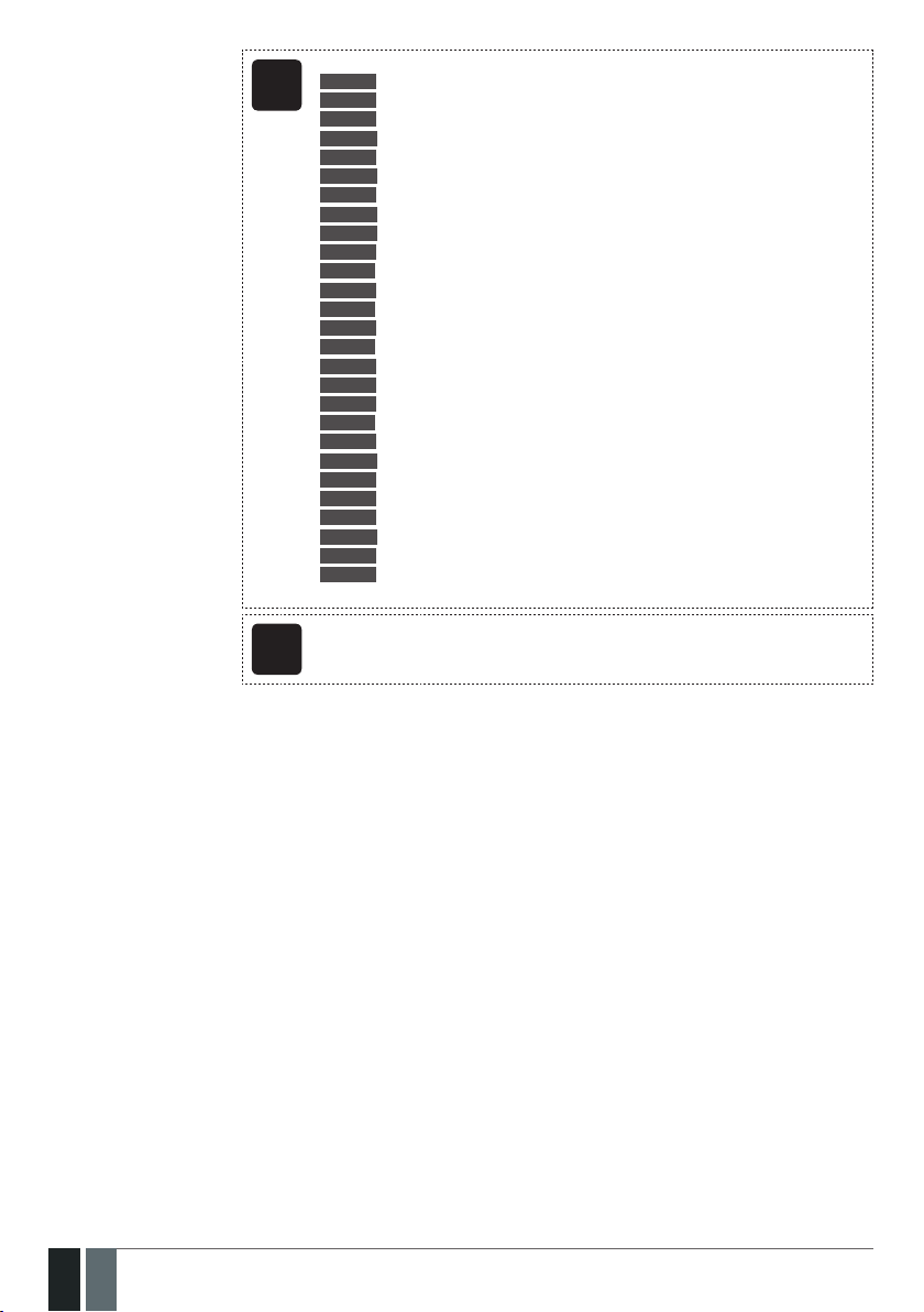
Seq. No. Contact ID® Code Event Description
1 1110 Fire alarm Transmitted in case a zone of Fire type is violated.
2 3110 Fire restore Transmitted in case a zone of Fire type is restored.
3 1121 Disarmed by user (Duress
4 1130 Burglary alarm Transmitted in case a zone of Delay (if not disarmed before entry delay
5 3130 Burglary restore Transmitted in case a zone of Delay (if not disarmed before entry delay
6 1133 24-Hour zone alarm Transmitted in case of zone of 24-Hour type is violated.
7 3133 24-Hour zone restore Transmitted in case of zone of 24-Hour type is restored.
8 1144 Tamper alarm Transmitted in case the tamper is violated.
9 3144 Tamper restore Transmitted in case the tamper is restored.
10 1146 Panic/Silent zone alarm Transmitted in case of zone of Panic/Silent type is violated.
11 3146 Panic/Silent zone restore Transmitted in case of zone of Panic/Silent type is restored.
12 1158 Temperature risen Transmitted in case of the temperature has increased above the MAX set
13 1159 Temperature fallen Transmitted in case of temperature has decreased below the MIN set value.
14 1301 Mains power loss Transmitted in case the main power supply is lost.
15 3301 Mains power restore Transmitted in case the main power supply is restored.
16 1302 Low battery Transmitted in case the backup battery voltage is 10.5V or lower / the
17 1308 System shutdown When the system is running on backup battery power, it transmits the data
18 1309 Battery failed Transmitted in case the backup battery resistance is 2 or higher.
19 1311 Battery dead or missing Transmitted in case the backup battery is not present or the battery volt-
20 3311 Battery connection restore Transmitted in case the backup battery connecton is xed.
21 1321 Siren fail Transmitted in case the siren is disconnected/broken.
22 3321 Siren restore Transmitted in case the siren is connected/xed.
23 1330 Keypad fail Transmitted in case the keypad is disconnected/broken.
24 3330 Keypad restore Transmitted in case the keypad is connected/xed
25 1354 GPRS connection loss
26 1358 GSM connection failed Transmitted in case the GSM connection is lost.
27 1359 GSM/GPRS antenna fail Transmitted in case the GSM/GPRS antenna is disconnected/broken
28 3359 GSM/GPRS antenna restore Transmitted in case the GSM/GPRS antenna is connected/xed.
29 1381 Wireless signal loss Transmitted in case the connection with any wireless device is lost.
30 3381 Wireless signal restore Transmitted in case the connection with any wireless device is restored.
31 1401 Disarmed by user Transmitted in case the system is disarmed.
32 3401 Armed by user Transmitted in case the system is armed.
33 1456 Disarmed in Stay mode Transmitted in case the system is disarmed in Stay mode.
34 3456 Armed in Stay mode Transmitted in case the system is armed in Stay mode.
35 1463 Disarmed by user (SGS
36 3463 Armed by user (SGS
37 1570 Zone bypassed Transmitted in case a violated zone is bypassed.
38 3570 Bypassed zone activated Transmitted in case a bypassed zone is activated.
39 1602 Test event/Kronos ping Transmitted for system online status verication purposes.
40 3626 Date/time not set Transmitted in case system date & time is not set.
41 1900 System started Transmitted on system startup.
password)
password)
password)
Transmitted in case the system is disarmed by Duress password.
countdown is completed), Interior Follower or Instant type is violated.
countdown is completed), Interior Follower or Instant type is restored.
value.
wireless sensor battery level runs below 5%.
message before the backup battery power is fully depleted.
age runs below 5V.
Transmitted in case the GPRS connection is lost.
Transmitted in case the system is disarmed by SGS password.
Transmitted in case the system is armed by SGS password.
MANUAL ELDES ESIM364 V1.5
101
101EN

The following table refers to user codes included in arm/disarm data messages.
Type Code
User Phone Number 1 0
User Phone Number 2 1
User Phone Number 3 2
User Phone Number 4 3
User Phone Number 5 4
User Phone Number 6 5
User Phone Number 7 6
User Phone Number 8 7
User Phone Number 9 8
User Phone Number 10 9
iButton 1 10
iButton 2 11
iButton 3 12
iButton 4 13
iButton 5 14
iButton 6 15
iButton 7 16
iButton 8 17
iButton 9 18
iButton 10 19
iButton 11 20
iButton 12 21
iButton 13 22
iButton 14 23
iButton 15 24
iButton 16 25
User Password 1 26
User Password 2 27
User Password 3 28
User Password 4 29
User Password 5 30
User Password 6 31
User Password 7 32
User Password 8 33
User Password 9 34
User Password 10 35
User Password 11 36
User Password 12 37
User Password 13 38
User Password 14 39
User Password 15 40
User Password 16 41
User Password 17 42
User Password 18 43
User Password 19 44
User Password 20 45
User Password 21 46
User Password 22 47
User Password 23 48
User Password 24 49
User Password 25 50
User Password 26 51
User Password 27 52
User Password 28 53
User Password 29 54
User Password 30 55
Remote Code (EGR100) 56
KeyFob 1 133
102
102 EN
MANUAL ELDES ESIM364 V1.5

KeyFob 2 134
KeyFob 3 135
KeyFob 4 136
KeyFob 5 137
Arm/Disarm by Zone 213
Disable data message
Menu path:
Burglary alarm/restore: OK → CONFIGURATION → OK → aaaa → OK → MS SETTINGS → OK →
EKB2
DATA MESSAGES 1 → OK → BURGLR ALM/REST EV → OK → DISABLE → OK
Mains power loss/restore: OK → CONFIGURATION → OK → aaaa → OK → MS SETTINGS → OK
→ DATA MESSAGES 1 → OK → MAIN POWER L/R EV → OK → DISABLE → OK
Armed/disarmed by user: OK → CONFIGURATION → OK → aaaa → OK → MS SETTINGS → OK
→ DATA MESSAGES 1 → OK → ARM/DISARM EVENT → OK → DISABLE → OK
Battery failed: OK → CONFIGURATION → OK → aaaa → OK → MS SETTINGS → OK → DATA
MESSAGES 1 → OK → BATTERY FAILED → OK → DISABLE → OK
Battery dead or missing/battery connection restore: OK → CONFIGURATION → OK → aaaa
→ OK → MS SETTINGS → OK → DATA MESSAGES 1 → OK → BATTERY DEAD/MISS → OK →
DISABLE → OK
Test event: OK → CONFIGURATION → OK → aaaa → OK → MS SETTINGS → OK → DATA
MESSAGES 1 → OK → TEST EVENT → OK → DISABLE → OK
Tamper alarm/restore: OK → CONFIGURATION → OK → aaaa → OK → MS SETTINGS → OK →
DATA MESSAGES 1 → OK → TAMPER ALM/REST EV → OK → DISABLE → OK
Panic/Silent zone alarm/restore: OK → CONFIGURATION → OK → aaaa → OK → MS
SETTINGS → OK → DATA MESSAGES 1 → OK → PA/SIL ALM/REST EV → OK → DISABLE → OK
System started: OK → CONFIGURATION → OK → aaaa → OK → MS SETTINGS → OK → DATA
MESSAGES 1 → OK → SYSTEM STARTED EV → OK → DISABLE → OK
Fire alarm/restore: OK → CONFIGURATION → OK → aaaa → OK → MS SETTINGS → OK →
DATA MESSAGES 1 → OK → FIRE ALM/REST EV → OK → DISABLE → OK
24-Hour zone alarm/restore: OK → CONFIGURATION → OK → aaaa → OK → MS SETTINGS →
OK → DATA MESSAGES 1 → OK → 24H ALM/REST EVENT→ OK → DISABLE → OK
Low battery: OK → CONFIGURATION → OK → aaaa → OK → MS SETTINGS → OK →DATA
MESSAGES 1 → OK → LOW BATTE RY EVENT → OK → DISABLE → OK
Temperature risen: OK → CONFIGURATION → OK → aaaa → OK → MS SETTINGS → OK →
DATA MESSAGES 1 → OK → TEMP HIGH EVENT → OK → DISABLE → OK
Temperature fallen: OK → CONFIGURATION → OK → aaaa → OK → MS SETTINGS → OK →
DATA MESSAGES 1 → OK → TEMP LOW EVENT → OK → DISABLE → OK
Wireless signal loss/restore: OK → CONFIGURATION → OK → aaaa → OK → MS SETTINGS →
OK → DATA MESSAGES 1 → OK → WLESS SIGN L/R EV → OK → DISABLE → OK
Disarmed by user (Duress password): OK → CONFIGURATION → OK → aaaa → OK → MS
SETTINGS → OK → DATA MESSAGES 2 → OK → DISARM DURESS EV → OK → DISABLE → OK
Armed/disarmed by user (SGS password): OK → CONFIGURATION → OK → aaaa → OK → MS
SETTINGS → OK → DATA MESSAGES 2 → OK → ARM/DARM SGS EVENT → OK → DISABLE →
OK
Armed/disarmed in Stay mode: OK → CONFIGURATION → OK → aaaa → OK → MS SETTINGS
→ OK → DATA MESSAGES 2 → OK → ARM/DARM STAY EV → OK → DISABLE → OK
Siren fail/restore: OK → CONFIGURATION → OK → aaaa → OK → MS SETTINGS → OK → DATA
MESSAGES 2 → OK → SIREN FAIL/REST EV → OK → DISABLE → OK
Date/time not set: OK → CONFIGURATION → OK → aaaa → OK → MS SETTINGS → OK → DATA
MESSAGES 2 → OK → DATE/TIME NOT SET → OK → DISABLE → OK
GSM connection failed: OK → CONFIGURATION → OK → aaaa → OK → MS SETTINGS → OK →
DATA MESSAGES 2 → OK → GSM CONNECT FAILED → OK → DISABLE → OK
GSM/GPRS antenna fail/restore: OK → CONFIGURATION → OK → aaaa → OK → MS SETTINGS
→ OK → DATA MESSAGES 2 → OK → GSM ANT FAIL/REST → OK → DISABLE → OK
System shutdown: OK → CONFIGURATION → OK → aaaa → OK → MS SETTINGS → OK →
DATA MESSAGES 2 → OK → SYSTEM SHUTDOWN EV → OK → DISABLE → OK
Keypad fail/restore: OK → CONFIGURATION → OK → aaaa → OK → MS SETTINGS → OK →
DATA MESSAGES 2 → OK → KEYPAD FAIL/REST → OK → DISABLE → OK
GPRS connection failed: OK → CONFIGURATION → OK → aaaa → OK → MS SETTINGS → OK →
DATA MESSAGES 2 → OK → GPRS CONNECT FAIL → OK → DISABLE → OK
Zone bypassed/activated: OK → CONFIGURATION → OK → aaaa → OK → MS SETTINGS → OK
→ DATA MESSAGES 2 → OK → ZONE BYPASS→ OK → DISABLE → OK
Value: aaaa – 4-digit administrator password.
MANUAL ELDES ESIM364 V1.5
103
103EN

Enter parameter 24, event number & parameter status value:
EKB3/
24 01 0 # – Burglary alarm/restore
EKB3W
24 02 0 # – Mains power loss/restore
24 03 0 # – Armed/disarmed by user
24 04 0 # – Test event
24 05 0 # – Battery failed
24 06 0 # –Battery dead or missing/battery connection restore
24 07 0 # – Tamper alarm/restore
24 08 0 # – Panic/Silent zone alarm/restore
24 09 0 # – Kronos ping
24 10 0 # – System started
24 13 0 # – 24-Hour zone alarm/restore
24 14 0 # – Fire zone alarm/restore
24 15 0 # – Low battery
24 16 0 # –Temperature risen
24 17 0 # – Temperature fallen
24 18 0 # – Wireless signal loss/restore
24 19 0 # – Disarmed by user (Duress password)
24 20 0 # – Armed/disarmed by user (SGS password)
24 21 0 # – Armed/disarmed in Stay mode
24 22 0 # – Siren fail/restore
24 24 0 # –Date/time not set
24 25 0 # – GSM connection failed
24 26 0 # – GSM/GPRS antenna fail/restore
24 27 0 # – System shutdown
24 28 0 # – Keypad fail/restore
24 29 0 # – GPRS connection failed
24 30 0 # – Zone bypassed/activated
Example: 24080#
104
104 EN
Cong
Tool
This operation may be carried out from the PC using the ELDES Conguration Tool software.
MANUAL ELDES ESIM364 V1.5

Enable data message
Menu path:
Burglary alarm/restore: OK → CONFIGURATION → OK → aaaa → OK → MS SETTINGS → OK →
EKB2
DATA MESSAGES 1 → OK → BURGLR ALM/REST EV → OK → ENABLE → OK
Mains power loss/restore: OK → CONFIGURATION → OK → aaaa → OK → MS SETTINGS → OK
→ DATA MESSAGES 1 → OK → MAIN POWER L/R EV → OK → ENABLE → OK
Armed/disarmed by user: OK → CONFIGURATION → OK → aaaa → OK → MS SETTINGS → OK
→ DATA MESSAGES 1 → OK → ARM/DISARM EVENT → OK → ENABLE → OK
Battery failed: OK → CONFIGURATION → OK → aaaa → OK → MS SETTINGS → OK → DATA
MESSAGES 1 → OK → BATTERY FAILED → OK → ENABLE → OK
Battery dead or missing/battery connection restore: OK → CONFIGURATION → OK → aaaa
→ OK → MS SETTINGS → OK → DATA MESSAGES 1 → OK → BATTERY DEAD/MISS → OK →
ENABLE → OK
Test event: OK → CONFIGURATION → OK → aaaa → OK → MS SETTINGS → OK → DATA
MESSAGES 1 → OK → TEST EVENT → OK → ENABLE → OK
Tamper alarm/restore: OK → CONFIGURATION → OK → aaaa → OK → MS SETTINGS → OK →
DATA MESSAGES 1 → OK → TAMPER ALM/REST EV → OK → ENABLE → OK
Panic/Silent zone alarm/restore OK → CONFIGURATION → OK → aaaa → OK → MS SETTINGS
→ OK → DATA MESSAGES 1 → OK → PA/SIL ALM/REST EV → OK → ENABLE → OK
System started: OK → CONFIGURATION → OK → aaaa → OK → MS SETTINGS → OK → DATA
MESSAGES 1 → OK → SYSTEM STARTED EV → OK → ENABLE → OK
Fire alarm/restore: OK → CONFIGURATION → OK → aaaa → OK → MS SETTINGS → OK →
DATA MESSAGES 1 → OK → FIRE ALM/REST EV → OK → ENABLE → OK
24-Hour zone alarm/restore: OK → CONFIGURATION → OK → aaaa → OK → MS SETTINGS →
OK → DATA MESSAGES 1 → OK → 24H ALM/REST EVENT→ OK → ENABLE → OK
Low battery: OK → CONFIGURATION → OK → aaaa → OK → MS SETTINGS → OK → DATA
MESSAGES 1 → OK → LOW BATTE RY EVENT → OK → ENABLE → OK
Temperature risen: OK → CONFIGURATION → OK → aaaa → OK → MS SETTINGS → OK →
DATA MESSAGES 1 → OK → TEMP HIGH EVENT → OK → ENABLE → OK
Temperature fallen: OK → CONFIGURATION → OK → aaaa → OK → MS SETTINGS → OK →
DATA MESSAGES 1 → OK → TEMP LOW EVENT → OK → ENABLE → OK
Wireless signal loss/restore: OK → CONFIGURATION → OK → aaaa → OK → MS SETTINGS →
OK → DATA MESSAGES 1 → OK → WLESS SIGN L/R EV → OK → ENABLE → OK
Disarmed by user (Duress password): OK → CONFIGURATION → OK → aaaa → OK → MS
SETTINGS → OK → DATA MESSAGES 2 → OK → DISARM DURESS EV → OK → ENABLE → OK
Armed/disarmed by user (SGS password): OK → CONFIGURATION → OK → aaaa → OK → MS
SETTINGS → OK → DATA MESSAGES 2 → OK → ARM/DARM SGS EVENT → OK → ENABLE → OK
Armed/disarmed in Stay mode: OK → CONFIGURATION → OK → aaaa → OK → MS SETTINGS
→ OK → DATA MESSAGES 2 → OK → ARM/DARM STAY EV → OK → ENABLE → OK
Siren fail/restore: OK → CONFIGURATION → OK → aaaa → OK → MS SETTINGS → OK → DATA
MESSAGES 2 → OK → SIREN FAIL/REST EV → OK → ENABLE → OK
Date/time not set: OK → CONFIGURATION → OK → aaaa → OK → MS SETTINGS → OK → DATA
MESSAGES 2 → OK → DATE/TIME NOT SET → OK → ENABLE → OK
GSM connection failed: OK → CONFIGURATION → OK → aaaa → OK → MS SETTINGS → OK →
DATA MESSAGES 2 → OK → GSM CONNECT FAILED → OK → ENABLE → OK
GSM/GPRS antenna fail/restore: OK → CONFIGURATION → OK → aaaa → OK → MS SETTINGS
→ OK → DATA MESSAGES 2 → OK → GSM ANT FAIL/REST → OK → ENABLE → OK
System shutdown: OK → CONFIGURATION → OK → aaaa → OK → MS SETTINGS → OK →
DATA MESSAGES 2 → OK → SYSTEM SHUTDOWN EV → OK → ENABLE → OK
Keypad fail/restore: OK → CONFIGURATION → OK → aaaa → OK → MS SETTINGS → OK →
DATA MESSAGES 2 → OK → KEYPAD FAIL/REST → OK → ENABLE → OK
GPRS connection failed: OK → CONFIGURATION → OK → aaaa → OK → MS SETTINGS → OK →
DATA MESSAGES 2 → OK → GPRS CONNECT FAIL → OK → ENABLE → OK
Zone bypassed/activated: OK → CONFIGURATION → OK → aaaa → OK → MS SETTINGS → OK
→ DATA MESSAGES 2 → OK → ZONE BYPASS→ OK → ENABLE → OK
Value: aaaa – 4-digit administrator password.
MANUAL ELDES ESIM364 V1.5
105
105EN
Enter parameter 24, event number & parameter status value:
EKB3/
24 01 1 # – Burglary alarm/restore
EKB3W
24 02 1 # – Mains power loss/restore
24 03 1 # – Armed/disarmed by user
24 04 1 # – Test event
24 05 1 # – Battery failed
24 06 1 # – Battery dead or missing/battery connection restore
24 07 1 # – Tamper alarm/restore
24 08 1 # – Panic/Silent zone alarm/restore
24 09 1 # – Kronos ping
24 10 1 # – System started
24 13 1 # – 24-Hour zone alarm/restore
24 14 1 # – Fire zone alarm/restore
24 15 1 # – Low battery
24 16 1 # – Temperature risen
24 17 1 # – Temperature fallen
24 18 1 # – Wireless signal loss/restore
24 19 1 # – Disarmed by user (Duress password)
24 20 1 # – Armed/disarmed by user (SGS password)
24 21 1 # – Armed/disarmed in Stay mode
24 22 1 # – Siren fail/restore
24 24 1 # –Date/time not set
24 25 1 # – GSM connection failed
24 26 1 # – GSM/GPRS antenna fail/restore
24 27 1 # – System shutdown
24 28 1 # – Keypad fail/restore
24 29 1 # – GPRS connection failed
24 30 1 # – Zone bypassed/activated
Example: 24031#
106
106 EN
Cong
Tool
This operation may be carried out from the PC using the ELDES Conguration Tool software.
MANUAL ELDES ESIM364 V1.5

30.2. Communication
The system supports the following communication methods and protocols:
• GPRS network – EGR100, Kronos protocol.
• Voice calls (GSM audio channel) – Ademco Contact ID protocol.
• RS485 data channel.
• CSD (Cricuit Switched Data).
• PSTN (landline) – Ademco Contact ID protocol.
• SMS – Cortex SMS format.
Any communication method can be set as primary or backup connection. The user can set up to 5 backup connections in any sequence order.
Initially, the system communicates via primary connection with the monitoring station. By default, if the initial attempt to transmit data is
unsuccessful, the system will make additional attempts until the data is successfully delivered. If all attempts are unsuccessful, the system
will follow this pattern:
a) The system switches to the backup connection that follows in the sequence (presumably - Backup 1).
b) The system then attempts to transmit data by the backup connection.
c) If the initial attempt is unsuccessful, the system will make additional attempts until the data is successfully delivered.
d) If the system ends up with all unsuccessful attempts, it will switch to the next backup connection in the sequence (presumably - Back-
up 2) and will continue to operate as described in the previous steps. The connection is considered unsuccessful under the following
conditions:
• GPRS network – The system has not received the ACK data message from the monitoring station within 40 seconds.
• Voice calls:
• The system has not received the “handshake” signal from the monitoring station within 40 seconds.
• The system has not received the “kisso” signal from the monitoring station within 5 attempts each lasting 1 second.
• CSD – The system has not received the ACK data message from the monitoring station within 35 seconds.
• PSTN:
• The system has not received the “handshake” signal from the monitoring station within 40 seconds.
• The system has not received the “kisso” signal from the monitoring station within 5 attempts each lasting 1 second.
• SMS – The system has not received the SMS delivery report from the SMSC (Short Message Service Center) within 45 seconds.
e) If one of the attempts is successful, the system will transmit all queued up data messages by this connection.
f) The system then returns to the primary connection and attempts to transmit the next data messages by primary connection.
g) If the system ends up with all unsuccessful attempts by all connections, it will wait until the Delay after last communication attempt
time (By default – 600 seconds) expires and will return to the primary connection afterwards.
h) If a new data message, except Test Event (ping), is generated during Delay after last communication attempt time, the system will
immediately attempt to transmit it to the monitoring station, regardless of Delay after last communication attempt being in progress.
MANUAL ELDES ESIM364 V1.5
107
107EN
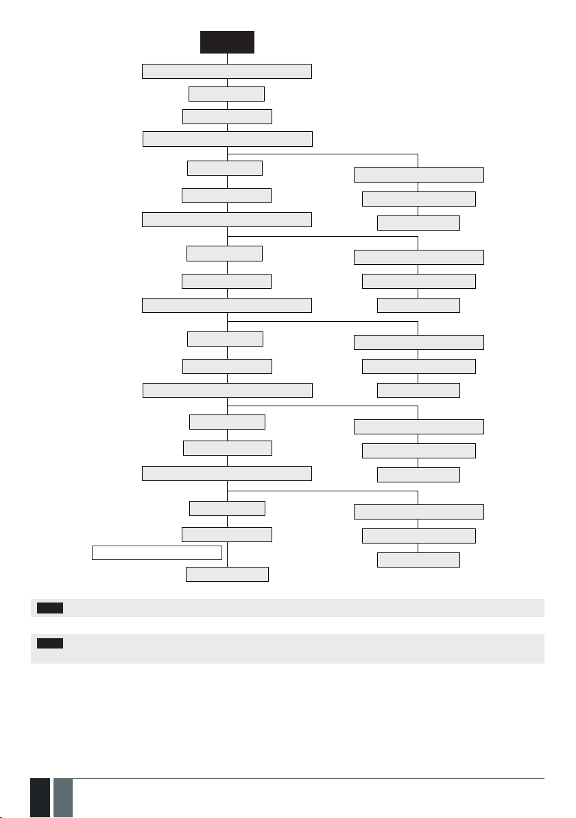
PRIMARY
Makes up to 3 or 5 attempts to transmit data
All attempts failed
Switches to BACKUP 1
Makes up to 3 or 5 attempts to transmit data
All attempts failed
Switches to BACKUP 2
Makes up to 3 or 5 attempts to transmit data
All attempts failed
Switches to BACKUP 3
Makes up to 3 or 5 attempts to transmit data
All attempts failed
Switches to BACKUP 4
Makes up to 3 or 5 attempts to transmit data
All attempts failed
Switches to BACKUP 5
Makes up to 3 or 5 attempts to transmit data
All attempts failed
Waits for 600 seconds
Delay after last communication attempt
Returns to PRIMARY
One of the attempts is successful
Transmits all queued up data
Returns to PRIMARY
One of the attempts is successful
Transmits all queued up data
Returns to PRIMARY
One of the attempts is successful
Transmits all queued up data
Returns to PRIMARY
One of the attempts is successful
Transmits all queued up data
Returns to PRIMARY
One of the attempts is successful
Transmits all queued up data
Returns to PRIMARY
NOTE: The number of attempts, indicated in the diagram, are default and depends on the determined communication method.
NOTE: When using Dual-SIM feature, the Secondary SIM card is involved in the communication process. For more details, please refer
to 31. DUAL SIM MANAGEMENT.
108
108 EN
MANUAL ELDES ESIM364 V1.5

Set primary connection
Menu path:
GPRS network: OK → CONFIGURATION → OK → aaaa → OK → MS SETTINGS → OK →
EKB2
PRIMARY CONNECTION → OK → GPRS → OK
Voice calls: OK → CONFIGURATION → OK → aaaa → OK → MS SETTINGS → OK → PRIMARY
CONNECTION → OK → VOICE CALLS → OK
RS485: OK → CONFIGURATION → OK → aaaa → OK → MS SETTINGS → OK → PRIMARY
CONNECTION → OK → RS485 → OK
CSD: OK → CONFIGURATION → OK → aaaa → OK → MS SETTINGS → OK → PRIMARY
CONNECTION → OK → CSD → OK
PSTN: OK → CONFIGURATION → OK → aaaa → OK → MS SETTINGS → OK → PRIMARY
CONNECTION → OK → PSTN → OK
SMS: OK → CONFIGURATION → OK → aaaa → OK → MS SETTINGS → OK → PRIMARY
CONNECTION → OK → SMS → OK
connection not in use: OK → CONFIGURATION → OK → aaaa → OK → MS SETTINGS → OK →
PRIMARY CONNECTION → OK → N/A → OK
Value: aaaa – 4-digit administrator password.
Enter parameter 48 & communication method number:
EKB3/
48 0 # – GPRS network
EKB3W
48 1 # – Voice calls
48 2 # – RS485
48 3 # – CSD
48 4 # – PSTN
48 5 # – SMS
48 6 # – connection not in use
Example: 484#
Set backup connection
1... 5
Cong
Tool
EKB2
EKB3/
EKB3W
Cong
Tool
This operation may be carried out from the PC using the ELDES Conguration Tool software.
Menu path:
GPRS network: OK → CONFIGURATION → OK → aaaa → OK → MS SETTINGS → OK → BACKUP
CONNECTION1... 5 → OK → GPRS → OK
Voice calls: OK → CONFIGURATION → OK → aaaa → OK → MS SETTINGS → OK → BACKUP
CONNECTION1... 5 → OK → VOICE CALLS → OK
RS485: OK → CONFIGURATION → OK → aaaa → OK → MS SETTINGS → OK → BACKUP
CONNECTION1... 5 → OK → RS485 → OK
CSD: K → CONFIGURATION → OK → aaaa → OK → MS SETTINGS → OK →
BACKUP CONNECTION1... 5 → OK → CSD → OK
PSTN: OK → CONFIGURATION → OK → aaaa → OK → MS SETTINGS → OK → BACKUP
CONNECTION1... 5 → OK → PSTN → OK
SMS: OK → CONFIGURATION → OK → aaaa → OK → MS SETTINGS → OK → BACKUP
CONNECTION1... 5 → OK → SMS → OK
connection not in use: OK → CONFIGURATION → OK → aaaa → OK → MS SETTINGS → OK →
BACKUP CONNECTION1... 5 → OK → N/A → OK
Value: aaaa – 4-digit administrator password.
Enter parameter 83, backup connection slot number & communication method
number:
83 bb 0 # – GPRS network
83 bb 1 # – Voice calls
83 bb 2 # – RS485
83 bb 3 # – CSD
83 bb 4 # – PSTN
83 bb 5 # – SMS
83 bb 6 # – connection not in use
Value: bb – backup connection slot number, range – [01... 05].
Example: 83021#
This operation may be carried out from the PC using the ELDES Conguration Tool software.
MANUAL ELDES ESIM364 V1.5
109
109EN

If all attempts by all set connections are unsuccessful, the system will wait until the delay time (By default – 600 seconds) expires and will
attempt to transmit data to the monitoring station again starting with the primary connection.
Set delay after last
communication
attempt
Cong
Menu path:
OK → CONFIGURATION → OK → aaaa → OK → MS SETTINGS → OK → DELAY LAST ATTEMPT
EKB2
→ OK → aaapp → OK
Value: aaaa – 4-digit administrator password; aaapp – duration of delay after last attempt,
range – [0... 65535] seconds.
Enter parameter 69 & duration of delay after last attempt:
EKB3/
69 aaapp #
EKB3W
Value: aaapp – duration of delay after last attempt, range – [0... 65535] seconds.
Example: 69200#
This operation may be carried out from the PC using the ELDES Conguration Tool software.
Tool
NOTE: 0 value disables delay after last communication attempt.
NOTE: The system is fully compatible with Kronos NET/Kronos LT monitoring station software for communication via GPRS network. When
using a dierent monitoring station software, EGR100 middleware is required. EGR100 is freeware and can be downloaded at www.eldes.lt/
en/download
30.2.1. GPRS Network
SMS text message content:
ssss_SETGPRS:IP:add.add.add.add
Set server IP address
SMS
Value: ssss – 4-digit SMS password; add.add.add.add – server IP address.
Example: 1111_SETGPRS:IP:65.82.119.5
Menu path:
OK → CONFIGURATION → OK → aaaa → OK → GPRS SETTINGS → OK → SERVER IP → OK →
EKB2
add.add.add.add → OK
Value: aaaa – 4-digit administartor password; add.add.add.add – server IP address.
Enter parameter 40 & server IP address:
EKB3/
40 add add add add #
EKB3W
Value: add add add add – server IP address.
Example: 40065082119005#
Set server port
110
110 EN
Cong
Tool
SMS
EKB2
EKB3/
EKB3W
Cong
Tool
This operation may be carried out from the PC using the ELDES Conguration Tool software.
SMS text message content:
ssss_SETGPRS:PORT:pprrt
Value: ssss – 4-digit SMS password; pprrt – server port number, range – [1... 65535].
Example: 1111_SETGPRS:PORT:5521
Menu path:
OK → CONFIGURATION → OK → aaaa → OK → GPRS SETTINGS → OK → SERVER PORT → OK
→ pprrt → OK
Value: aaaa – 4-digit administartor password; pprrt – server port number, range – [1...
65535].
Enter parameter 44 & server port number:
44 pprrt #
Value: pprrt – server port number, range – [1... 65535].
Example: 443365#
This operation may be carried out from the PC using the ELDES Conguration Tool software.
MANUAL ELDES ESIM364 V1.5

Set DNS1 server IP
address
Menu path:
OK → CONFIGURATION → OK → aaaa → OK → GPRS SETTINGS → OK → DNS1 → OK → add.
EKB2
add.add.add → OK
Value: aaaa – 4-digit administartor password; add.add.add.add – DNS1 server IP address.
Enter parameter 41 & DNS1 server IP address:
EKB3/
41 add add add add #
EKB3W
Value: add add add add – DNS1 server IP address.
Example: 41065082119001#
Set DNS2 server IP
address
Set protocol
Cong
Tool
EKB2
EKB3/
EKB3W
Cong
Tool
SMS
EKB2
EKB3/
EKB3W
Cong
Tool
This operation may be carried out from the PC using the ELDES Conguration Tool software.
Menu path:
OK → CONFIGURATION → OK → aaaa → OK → GPRS SETTINGS → OK → DNS2 → OK → add.
add.add.add → OK
Value: aaaa – 4-digit administartor password; add.add.add.add – DNS2 server IP address.
Enter parameter 42 & DNS2 server IP address:
42 add add add add #
Value: add add add add – DNS2 server IP address.
Example: 41065082119002#
This operation may be carried out from the PC using the ELDES Conguration Tool software.
SMS text message content:
ssss_SETGPRS:PROTOCOL:ptc
Value: ssss – 4-digit SMS password; ptc – protocol, range – [TCP... UDP].
Example: 1111_SETGPRS:PROTOCOL:UDP
Menu path:
OK → CONFIGURATION → OK → aaaa → OK → GPRS SETTINGS → OK → PROTOCOL → OK →
TCP | UDP → OK
Value: aaaa – 4-digit administartor passw
Enter parameter 43 & protocol number:
43 0 # - TCP
43 1 # - UDP
Example: 431#
This operation may be carried out from the PC using the ELDES Conguration Tool software.
Set data format as
Kronos or EGR100
NOTE: Kronos NET/Kronos LT software communicates via TCP protocol, while EGR100 middle-ware v1.2 and up supports both – TCP and
UDP protocols. However, TCP protocol is NOT recommend to use with EGR100.
Set APN
Cong
Tool
SMS
This operation may be carried out from the PC using the ELDES Conguration Tool software.
SMS text message content:
ssss_SETGPRS:APN:acc-point-name
Value: ssss – 4-digit SMS password; acc-point-name – up to 31 character APN (Access Point
Name) provided by the GSM operator.
Example: 1111_SETGPRS:APN:internet
MANUAL ELDES ESIM364 V1.5
111
111EN

Set user name
Cong
Tool
SMS
This operation may be carried out from the PC using the ELDES Conguration Tool software.
SMS text message content:
ssss_SETGPRS:USER:usr-name
Value: ssss – 4-digit SMS password; usr-name – up to 31 character user name provided by
the GSM operator.
Example: 1111_USER:mobileusr
Cong
Set password
Cong
By default, if the initial attempt to transmit data to the monitoring station via GPRS network method is unsuccessful, the system will make
up to 2 additional attempts. If all attempts are unsuccessful, the system will switch to next backup connection that follows in the sequence
and will attempt to transmit data until it is successfully delivered to the monitoring station.
Set attempts
This operation may be carried out from the PC using the ELDES Conguration Tool software.
Tool
SMS text message content:
ssss_SETGPRS:PSW:password
SMS
Value: ssss – 4-digit SMS password; password – up to 31 character password provided by
the GSM operator.
Example: 1111_SETGPRS:PSW:mobilepsw
This operation may be carried out from the PC using the ELDES Conguration Tool software.
Tool
Menu path:
OK → CONFIGURATION → OK → aaaa → OK → MS SETTINGS → OK → GPRS SETTINGS → OK
EKB2
→ GPRS ATTEMPTS → OK → att → OK
Value: aaaa – 4-digit administrator password; att – number of attempts, range – [1... 255].
Enter parameter 68 & number of attempts:
EKB3/
68 att #
EKB3W
Value: att – number of attempts, range – [01... 255].
Example: 6809#
Cong
To report the online status, the system periodically transmits (By default – every 180 seconds) Test Event data message (ping) to the
monitoring station via GPRS network.
This operation may be carried out from the PC using the ELDES Conguration Tool software.
Tool
Set test period
NOTE: 0 value disables test period.
112
112 EN
EKB2
EKB3/
EKB3W
Cong
Tool
Menu path:
OK → CONFIGURATION → OK → aaaa → OK → MS SETTINGS → OK → GPRS SETTINGS → OK
→ TEST PERIOD → OK → tteessttpp → OK
Value: aaaa – 4-digit administrator password; tteessttpp – test period, range – [0... 65535]
seconds.
Enter parameter 46 & number of attempts:
46 tteessttpp #
Value: tteessttpp – test period, range – [0... 65535] seconds.
Example: 46120#
This operation may be carried out from the PC using the ELDES Conguration Tool software.
MANUAL ELDES ESIM364 V1.5

Unit ID is a 4-digit number (By default – 0000) required to identify the alarm system unit by EGR100 middle-ware. It is MANDATORY to
change the default Unit ID before using EGR100.
Menu path:
OK → CONFIGURATION → OK → aaaa → OK → MS SETTINGS → OK → GPRS SETTINGS → OK
Set unit ID
EKB2
→ UNIT ID → OK → unid → OK
Value: aaaa – 4-digit administartor password; unid – 4-digit unit ID number.
Enter parameter 47 & unit ID number:
EKB3/
47 unid #
EKB3W
Value: unid – 4-digit unit ID number.
Example: 472245#
View GPRS network
settings
Cong
Cong
This operation may be carried out from the PC using the ELDES Conguration Tool software.
Tool
SMS text message content:
SMS
ssss_SETGPRS?
Example: 1111_SETGPRS?
This operation may be carried out from the PC using the ELDES Conguration Tool software.
Tool
30.2.2. Voice Calls and SMS
The system supports up to 3 monitoring station phone numbers for communication with the alarm system by Voice Calls or SMS communication method. Tel. Number 1 is mandatory, the other two can be used as backup phone numbers and are not necessary. The supported
phone number formats are the following:
• International (with plus) – The phone numbers must be entered starting with plus and an international country code in the follow-
ing format: +[international code][area code][local number], example for UK: +4417091111111. This format can be used when setting
up the phone number by ELDES Conguration Tool software.
• International (with 00) – The phone numbers must be entered starting with 00 and an international country code in the following
format: 00[international code][area code][local number], example for UK: 004417091111111. This format can be used when setting
up the phone number by EKB2/EKB3/EKB3W keypad.
• Local – The phone numbers must be entered starting with an area code in the following format: [area code][local number], example
for UK: 017091111111. This format can be used when setting up the phone number by EKB2/EKB3/EKB3W keypad and ELDES Cong-
uration Tool software.
Menu path:
Set monitoring station
phone number
OK → CONFIGURATION → OK → aaaa → OK → MS SETTINGS → OK → VOICE CALLS/SMS ST →
EKB2
OK → TEL. NUMBER 1... 3 → OK → ttteeellnnuumm → OK
Value: aaaa – 4-digit administrator password; ttteeellnnuumm – up to 15 digits monitoring
station phone number.
Enter parameter 26, phone number slot & phone number:
EKB3/
26 ps ttteeellnnuumm #
EKB3W
Value: ps – phone number slot, range – [01... 03]; ttteeellnnuumm – up to 15 digits monito-
ring station phone number.
Example: 2601004417091111111#
Delete monitoring
station phone number
MANUAL ELDES ESIM364 V1.5
Cong
Tool
EKB2
This operation may be carried out from the PC using the ELDES Conguration Tool software.
Menu path:
OK → CONFIGURATION → OK → aaaa → OK → MS SETTINGS → OK → VOICE CALLS/SMS ST →
OK → TEL. NUMBER 1... 3 → OK → OK
Value: aaaa – 4-digit administrator password.
113
113EN

Cong
By default, if the initial attempt to transmit data to the monitoring station’s Tel Number 1 via Voice Calls or SMS method is unsuccessful, the
system will make up to 4 additional attempts. After all unsuccessful attempts, the system will continue to communicate with the monitoring station by switching to the next phone number that follows in the sequence and making up to 4 additional attempts if the initial attempt is unsuccessful. If all attempts to all phone numbers are unsuccessful, the system will switch to next backup connection that follows
in the sequence and will attempt to transmit data until it is successfully delivered to the monitoring station.
Set attempts
This operation may be carried out from the PC using the ELDES Conguration Tool software.
Tool
Menu path:
OK → CONFIGURATION → OK → aaaa → OK → MS SETTINGS → OK → VOICE CALLS/SMS ST →
EKB2
OK → ATTEMPTS → OK → at → OK
Value: aaaa – 4-digit administrator password; at – number of attempts, range – [1... 10].
Enter parameter 37 & number of attempts:
EKB3/
37 at #
EKB3W
Value: at – number of attempts, range – [01... 10].
Example: 3706#
Cong
Due to the individual conguration of each monitoring station, the system may fail to deliver the data message via Voice Calls communication method. In such cases it is recommended to adjust the microphone gain until the optimal value, leading to successful data message
delivery, is discovered.
Set microphone gain
This operation may be carried out from the PC using the ELDES Conguration Tool software.
Tool
Menu path:
OK → CONFIGURATION → OK → aaaa → OK → PRIMARY SETT INGS → OK → GSM AUDIO → OK
EKB2
→ MICROPHONE GAIN → OK → mg → OK
Value: aaaa – 4-digit administrator password; mg – microphone gain, range – [0... 15].
Cong
This operation may be carried out from the PC using the ELDES Conguration Tool software.
Tool
30.2.3. PSTN
The system supports up to 3 monitoring station phone numbers for communication with the alarm system by PSTN communication method. Tel. Number 1 is mandatory, the other two can be used as backup phone numbers and are not necessary. The supported phone number
formats are the following:
• International (with 00) – The phone numbers must be entered starting with 00 and an international country code in the following
format: 00[international code][area code][local number], example for UK: 004417091111111. This format can be used when setting
up the phone number by EKB2/EKB3/EKB3W keypad and ELDES Conguration Tool software..
• Local – The phone numbers must be entered starting with an area code in the following format: [area code][local number], example
for UK: 017091111111. This format can be used when setting up the phone number by EKB2/EKB3/EKB3W keypad and ELDES Cong-
uration Tool software.
Menu path:
Set monitoring station
phone number
OK → CONFIGURATION → OK → aaaa → OK → MS SETTINGS → OK → PSTN SETTINGS → OK
EKB2
→ TEL. NUMBER 1... 3 → OK → ttteeellnnuumm → OK
Value: aaaa – 4-digit administrator password; ttteeellnnuumm – up to 15 digits monitoring
station phone number.
Enter parameter 58, phone number slot & phone number:
EKB3/
58 ps ttteeellnnuumm #
EKB3W
Value: ps – phone number slot, range – [01... 03]; ttteeellnnuumm – up to 15 digits monito-
ring station phone number.
Example: 5802004417091111111#
114
114 EN
MANUAL ELDES ESIM364 V1.5

Delete monitoring
station phone number
Cong
Tool
EKB2
This operation may be carried out from the PC using the ELDES Conguration Tool software.
Menu path:
OK → CONFIGURATION → OK → aaaa → OK → MS SETTINGS → OK → PSTN SETTINGS → OK
→ TEL. NUMBER 1... 3 → OK → OK
Value: aaaa – 4-digit administrator password
Cong
By default, if the initial attempt to transmit data to the monitoring station’s Tel Number 1 via PSTN method is unsuccessful, the system
will make up to 4 additional attempts. After all unsuccessful attempts, the system will switch to the next phone number that follows
in the sequence and will make up to 4 additional attempts if the initial attempt is unsuccessful. If all attempts to all phone numbers are
unsuccessful, the system will switch to next backup connection that follows in the sequence and will attempt to transmit data until it is
successfully delivered to the monitoring station.
Set attempts
This operation may be carried out from the PC using the ELDES Conguration Tool software.
Tool
Menu path:
OK → CONFIGURATION → OK → aaaa → OK → MS SETTINGS → OK → PSTN SETTINGS → OK
EKB2
→ ATTEMPTS → OK → at → OK
Value: aaaa – 4-digit administrator password; at – number of attempts, range – [1... 10].
Enter parameter 91 & number of attempts:
EKB3/
91 at #
EKB3W
Value: at – number of attempts, range – [01... 10].
Example: 9108#
Cong
This operation may be carried out from the PC using the ELDES Conguration Tool software.
Tool
30.2.4. CSD
The system supports up to 5 monitoring station phone numbers for communication with the alarm system by CSD communication method.
Tel. Number 1 is mandatory, the other four can be used as backup phone numbers and are not necessary. The supported phone number
formats are the following:
• International (with plus) – The phone number must be entered starting with plus and an international country code in the following
format: +[international code][area code][local number], example for UK: +4417091111111. This format can be used when setting up
the phone number by ELDES Conguration Tool software.
• International (with 00) – The phone number must be entered starting with 00 and an international country code in the following ž
format: 00[international code][area code][local number], example for UK: 004417091111111. This format can be used when setting
up the phone number by EKB2/EKB3/EKB3W keypad.
Set monitoring station
phone number
MANUAL ELDES ESIM364 V1.5
EKB2
EKB3/
EKB3W
Cong
Tool
Menu path:
OK → CONFIGURATION → OK → aaaa → OK → MS SETTINGS → OK → CSD SETTINGS → OK →
TEL. NUMBER 1... 5 → OK → ttteeellnnuumm → OK
Value: aaaa – 4-digit administrator password; ttteeellnnuumm – up to 15 digits monitoring
station phone number.
Enter parameter 85, number of entry & phone number:
85 ps ttteeellnnuumm #
Value: ps – phone number slot, range – [01... 05]; ttteeellnnuumm – up to 15 digits monito-
ring station phone number.
Example: 8501004417091111111#
This operation may be carried out from the PC using the ELDES Conguration Tool software.
115
115EN

Delete monitoring
station phone number
Menu path:
OK → CONFIGURATION → OK → aaaa → OK → MS SETTINGS → OK → CSD SETTINGS → OK →
EKB2
TEL. NUMBER 1... 5 → OK → OK
Value: aaaa – 4-digit administrator password.
Cong
By default, if the initial attempt to transmit data to the monitoring station’s phone number via CSD method is unsuccessful, the system will
make up to 4 additional attempts. If all attempts are unsuccessful, the system will switch to next backup connection that follows in the
sequence and will attempt to transmit data until it is successfully delivered to the monitoring station.
Set attempts
This operation may be carried out from the PC using the ELDES Conguration Tool software.
Tool
Menu path:
OK → CONFIGURATION → OK → aaaa → OK → MS SETTINGS → OK → CSD SETTINGS → OK →
EKB2
ATTEMPTS → OK → at → OK
Value: aaaa – 4-digit administrator password; at – number of attempts, range – [1... 10].
Enter parameter 84 & number of attempts:
EKB3/
84 at #
EKB3W
Value: at – number of attempts, range – [01... 10].
Example: 8403#
Cong
This operation may be carried out from the PC using the ELDES Conguration Tool software.
Tool
116
116 EN
MANUAL ELDES ESIM364 V1.5

31. DUAL SIM MANAGEMENT
The Dual-SIM feature allows the system to operate with one of the two inserted SIM cards identied as Primary SIM and Secondary SIM
respectively. The Primary SIM card works as the main default card, while the Secondary SIM card is intended for backup purposes or addition
to the Primary SIM card - SMS text message sending/calling to the preset user phone number and/or communication with the monitoring
station.
The Dual-SIM feature can operate in one of the following modes:
• Disabled – The Secondary SIM card will not be functional and the system operates with Primary SIM card only (by default – enabled).
• Automatic – The system switches between the SIM cards in case of a GSM connection or one of the SIM cards failure.
• Manual – Provides a fully customizable set up of switching between the SIM cards. FOR ADVANCED USERS ONLY!
Manage Dual -SIM
feature
NOTE: Regardless of the selected mode, only one of the two SIM cards can operate at the same time.
31.1. Disabled Mode
Disabled mode is the default system mode that does not involve the Secondary SIM in the communication process. When this mode is in
use, the system will ignore the Secondary SIM card even if inserted in the SIM card slot.
For more details on how the system communicates with the user and the monitoring station in Disabled mode, please refer to 17. ALARM
INDICATIONS AND NOTIFICATIONS and 30.2. Communication respectively.
31.2. Automatic Mode
Automatic mode involves both SIM cards in the communication process. In this mode there is no Primary or Secondary SIM card hierarchy,
since both cards are equal and the SIM card that is currently in use maintains the GSM connection at all time, unless a failure occurs and the
other card would replace the previous one.
When one of the SIM card fails, the system attempts to re-establish a connection with it by starting an initial reconnection for a set number
of attempts (by default - 3 attempts). If all attempts fail, the system will switch to the other SIM card. If the other SIM card is responsive and
a GSM connection is successfully established, the system will remain operating with that SIM card until it fails. However, if the other SIM
card is unresponsive or it is not present in the SIM card slot, the system will return to the previous SIM card and attempt to establish a GSM
connection with it. If the system fails to carry out this action, after a single attempt it will switch to the other SIM card. This cycle continues
until one of the SIM cards responds and a GSM connection is successfully established. When the SIM card fails, the system will once again
attempt to restore the GSM connection for a set number of attempts (by default – 3 attempts). If all attempts fail, the cycle will continue as
described previously.
In Automatic mode the priority is to transmit data to the monitoring station, but if an event, which requires the system to send an SMS text
message occurs , the system will send the SMS text message via the SIM card that is currently in use. This can only be carried out under
the following conditions:
• among the attempts to transmit data to the monitoring station (depending on communication method).
• while switching the monitoring station connections.
• while switching between the SIM cards.
The following example indicates the situation described above.
Cong
Tool
This operation may be carried out from the PC using the ELDES Conguration Tool software.
MANUAL ELDES ESIM364 V1.5
117
117EN

Makes up to 3 or 5 attempt to transmit data via PRIMARY connection on Primary SIM
One of the attempts successful
Transmits all queued up data
Returns to PRIMARY connection on Primary SIM
All attempts failed
Switches to BACKUP1 connection on Primary SIM
Makes 1 attempt to transmit data via BACKUP1
connection on Primary SIM, but it is unsuccessful
SMS text message queues up for
sending to user phone number
Attempts to send the text message to user phone number
SMS delivery successful
Continues making the rest of the
attempts (2 or 4) to transmit data via
BACKUP1 connection on Primary SIM
All attempts failed
Switches to BACKUP2 connection on Primary SIM
Makes up to 3 or 5 attempts
to transmit data via BACKUP2
connection on Primary SIM
Primary SIM card ERROR
Makes up to 3 attempts to
re-establish GSM connection on Primary SIM card
One of the attempts successful
Continues transmitting data via PRIMARY connection on Primary SIM card
SMS delivery failed
Attempts to send SMS text message
to next available user phone number
All users unavailable
One of the users available
Sends the SMS text message
118
118 EN
Makes up to 3 or 5 attempts to transmit data
via BACKUP2 connection on Primary SIM
Waits for 600 seconds
Returns to PRIMARY connection on Primary SIM
Continued in next page
One of the attempts to re-establish GSM connection successful
One of the attempts successfulAll attempts failed
Transmits all queued up data
Delay after last communication attempt
Returns to PRIMARY connection on Primary SIM
MANUAL ELDES ESIM364 V1.5

Continued from previous page
All attempts failed
Makes 1 attempt to switch
to Secondary SIM card
Attempt successful
Makes up to 3 or 5 attempts to transmit data
via BACKUP2 connection on Secondary SIM
One of the attempts successful
Transmits all queued up data
Returns to PRIMARY connection on Primary SIM
Continues operating on Secondary SIM until the card fails
Waits for 600 seconds
Delay after last communication attempt
Returns to PRIMARY connection on Primary SIM
Continues operating on Secondary SIM until the card fails
Attempt successful
Continues operating on Primary SIM until the card fails
All attempts failed
Makes 1 attempt to switch
to Primary SIM card
All attempts failedAll attempts failed
Makes 1 attempt to switch
to Secondary SIM card
Continues switching between
the SIM cards until one is available
NOTE: The number of attempts, indicated in the diagram, are default and depends on the determined communication method
31.3. Manual Mode
Manual mode allows to use both - Primary and Secondary SIM cards and fully customize the algorithm of the communication. The system
can be set up to send SMS text messages/call to the preset user phone number and/or communicate with the monitoring station as follows:
• Primary SIM – Determines that the SMS text messages/calls/data will be transmitted via the Primary SIM card.
• Secondary SIM – Determines that the SMS text messages/calls/data will be transmitted via the Secondary SIM card.
• Currently in use SIM – Determines that the SMS text messages/calls/data will be transmitted via the SIM card that the system is
currently switched to - either Primary or the Secondary SIM card.
• Return to Primary SIM Enabled – Determines that the Primary SIM card will be the main SIM card of the system. If it is set up to use
the Secondary SIM in the communication process, the system will do so, but after completing the task via the Secondary SIM card, the
system will always return to the Primary SIM card
• Try to nd operator for a maximum of x times – Determines the maximum number of attempts the system should attempt to
re-establish a GSM connection on the current SIM card in case of unsuccessful initial attempt (by default – 3 attempts).
In Manual mode the priority is to transmit data to the monitoring station, but if an event, which requires the system to send an SMS text
message via one of the SIM cards, occurs , the system will switch to the requested SIM card and send the SMS text message. This can only
be carried out under the following conditions:
• among the attempts to transmit data to the monitoring station (depending on communication method).
• while switching the monitoring station connections.
• while switching between the SIM cards.
Example: System settings are the following:
Dual SIM Management:
• Manual Mode selected
• Return to Primary SIM – Disabled.
• Send SMS / Call via – Secondary SIM.
MS Settings – Communication:
• Primary – Voice Calls via Secondary SIM.
• Backup1 – CSD via Primary SIM.
• Backup2 – GPRS Network via Primary SIM.
Let’s say, the system is congured to send an SMS text message to user phone number in case of a Fire Zone Alarm and to transmit data to
MANUAL ELDES ESIM364 V1.5
119
119EN
 Loading...