

Eldes ESIM264 Installation Manual

ESIM264
GSM ALARM AND MANAGEMENT SYSTEM
INSTALLATION MANUAL
COMPLIES WITH EN 50131-1 GRADE 2, CLASS II REQUIREMENTS
Installation Manual v3.2
Valid for ESIM264 v7.15.00 and up
Safety instructions
Please read and follow these safety guidelines in order to maintain safety of operators and people around:
• GSM alarm and management system ESIM264 (also referenced as “alarm system”, “system“ or “device”) has radio transceiver operating
in GSM 850/900/1800/1900 bands.
• DO NOT use the system where it can be interfere with other devices and cause any potential danger.
• DO NOT use the system with medical devices.
• DO NOT use the system in hazardous environment.
• DO NOT expose the system to high humidity, chemical environment or mechanical impacts.
• DO NOT attempt to personally repair the system.
• System label is on the bottom side of the device.
GSM alarm system ESIM264 is a device mounted in limited access areas. Any system repairs must be done only by qualied,
safety aware personnel.
The system must be powered by main 16-24V 50 Hz ~1.5A max or 18-24V 1,5A max DC power supply which must be
approved by LST EN 60950-1 standard and be easily accessible nearby the device. When connecting the power supply to the
system, switching the pole terminals places does not have any aect.
Any additional devices linked to the system ESIM264 (computer, sensors, relays etc.) must be approved by LST EN 60950-1
standard.
The power supply can be connected to AC mains only inside installation room
with automatic 2-pole circuit breaker capable of disconnecting circuit in the
event of short circuit or over-current condition. Open circuit breaker must have
a gap between connections of more than 3mm (0.12in) and the disconnection
current 5A.
Mains power and backup battery must be disconnected before any installation or tuning work starts. The system installation
or maintenance must not be done during stormy conditions
Backup battery must be connected via the connection which in the case of breaking would result in disconnection of one of
battery pole terminals. Special care must be taken when connecting positive and negative battery terminals. Switching the
pole terminals places is NOT allowed.
AC/DC
ESIM264
USB cable
AC 230V
50 Hz/DC 24V
Phase
Null
PE
In order to avoid re or explosion hazards the system must be used only with approved backup battery.
The device is fully turned o by disconnecting 2-pole switch o device of the mains power and disconnecting backup battery
connector.
Fuse F1 type – Slow Blown 3A. Replacement fuses have to be exactly the same as indicated by the manufacturer.
If you use I security class computer for setting the parameters it must be connected to earth.
The WEEE (Waste Electrical and Electronic Equipment) marking on this product (see left) or its documentation indicates that
the product must not be disposed of together with household waste. To prevent possible harm to human health and/or the
environment, the product must be disposed on in an approved and environmentally safe recycling process. For further information on how to dispose of this product correctly, contact the system supplier, or the local authority responsible for waste
disposal in your area.
Contents
1. GENERAL INFORMATION .........................................................................................................................................................6
1.1. Functionality ......................................................................................................................................................................................................6
1.2. Compatible Device Overview ...........................................................................................................................................................................6
1.3. Default Parameters and Ways of Parameter Conguration .......................................................................................................................6
2. Technical Specications .......................................................................................................................................................10
2.1. Electrical and Mechanical Characteristics ...................................................................................................................................................10
2.2. Main Unit, LED and Connector Functionality ..............................................................................................................................................11
2.3. Wiring Diagrams ..............................................................................................................................................................................................12
3. INSTALLATION .......................................................................................................................................................................18
4. GENERAL OPERATIONAL DESCRIPTION ...............................................................................................................................22
5. CONFIGURATION METHODS ..................................................................................................................................................23
5.1. SMS Text Messages ........................................................................................................................................................................................23
5.2. EKB2 LCD Keypad.............................................................................................................................................................................................23
5.3. EKB3 LED Keypad ............................................................................................................................................................................................23
5.4. ELDES Conguration Tool Software ............................................................................................................................................................ 24
6. PASSWORDS ...........................................................................................................................................................................25
7. SYSTEM LANGUAGE .............................................................................................................................................................. 26
8. USER PHONE NUMBERS ........................................................................................................................................................27
8.1. System Control from any Phone Number ................................................................................................................................................... 28
9. DATE AND TIME ..................................................................................................................................................................... 29
10. USER CODES .......................................................................................................................................................................... 30
11. iBUTTON KEYS .......................................................................................................................................................................32
11.1. Adding and Removing iButton Keys .............................................................................................................................................................32
12. ARMING AND DISARMING ..................................................................................................................................................... 34
12.1. Free of Charge Phone Call ............................................................................................................................................................................. 34
12.2. SMS Text Message...........................................................................................................................................................................................35
12.3. EKB2 Keypad and User Code..........................................................................................................................................................................35
12.4. EKB3 Keypad and User Code......................................................................................................................................................................... 36
12.5. iButton Key .......................................................................................................................................................................................................37
12.6. EWK1/EWK2 Wireless Keyfob .......................................................................................................................................................................37
12.7. Arm-Disarm by Zone ...................................................................................................................................................................................... 38
12.8. Disabling and Enabling Arm/Disarm Notications.................................................................................................................................... 39
13. EXIT AND ENTRY DELAY ........................................................................................................................................................41
14. ZONES .................................................................................................................................................................................... 43
14.1. Zone Numbering ............................................................................................................................................................................................. 43
14.2. Zone Expansion .............................................................................................................................................................................................. 43
14.3. 6-Zone Mode ................................................................................................................................................................................................... 43
14.4. ATZ (Advanced Technology Zone) Mode ....................................................................................................................................................44
14.5. Zone Type Denitions ................................................................................................................................................................................... 45
14.6. Zone Attributes .............................................................................................................................................................................................. 46
14.7. Bypassing and Activating Zones.................................................................................................................................................................. 48
14.8. Zone Names .................................................................................................................................................................................................... 49
14.9. Disabling and Enabling Zones ...................................................................................................................................................................... 50
15. STAY MODE .............................................................................................................................................................................51
16. TAMPERS ................................................................................................................................................................................52
16.1. Tamper Names .................................................................................................................................................................................................52
17. ALARM INDICATIONS AND NOTIFICATIONS FOR USER .........................................................................................................53
17.1. Enabling and Disabling Alarm Notications ............................................................................................................................................... 54
18. PROGRAMMABLE (PGM) OUTPUTS .......................................................................................................................................57
18.1. PGM Output Numbering ................................................................................................................................................................................. 57
18.2. PGM Output Expansion ................................................................................................................................................................................... 57
18.3. PGM Output Names ........................................................................................................................................................................................ 58
18.4. Turning PGM Outputs ON and OFF ............................................................................................................................................................... 58
18.5. PGM Output Control by Event and Scheduler ............................................................................................................................................ 60
18.6. Wireless PGM Output Type Denitions ........................................................................................................................................................61
2
23EN
MANUAL ELDES ESIM264 V3.2 MANUAL ELDES ESIM264 V3.2
3
EN

Contents
19. WIRELESS DEVICES ............................................................................................................................................................... 62
19.1. Pairing, Removing and Replacing Wireless Device ................................................................................................................................... 62
19.2. Wireless Device Information......................................................................................................................................................................... 63
19.3. Wireless Signal Status Monitoring .............................................................................................................................................................. 64
19.4. Disabling and Enabling Siren if Wireless Signal is Lost ............................................................................................................................ 64
19.5. EWT1 - Wireless Transmitter-Receiver ....................................................................................................................................................... 65
19.6. EWF1 - Wireless Smoke Detector ................................................................................................................................................................ 66
19.7. EW2 - Wireless Zone and PGM Output Expansion Module ...................................................................................................................... 67
20. WIRED SIREN/BELL .............................................................................................................................................................. 68
20.1. Bell Squawk ..................................................................................................................................................................................................... 69
20.2. Indication by EWS2 - Wireless Outdoor Siren Indicators ......................................................................................................................... 69
20.3. Indication by EWS3 - Wireless Indoor Siren Indicators ............................................................................................................................. 70
21. BACKUP BATTERY, MAINS POWER STATUS MONITORING AND MEMORY............................................................................71
21.1. Backup Battery Status Monitoring ...............................................................................................................................................................71
21.2. Mains Power Status Monitoring ....................................................................................................................................................................72
21.3. Memory .............................................................................................................................................................................................................73
22. GSM CONNECTION STATUS MONITORING .............................................................................................................................74
23. PARTITIONS ...........................................................................................................................................................................74
23.1. Zone Partition ..................................................................................................................................................................................................74
23.2. User Phone Number Partition .......................................................................................................................................................................74
23.3. Keypad Partition and Keypad Partition Switch ...........................................................................................................................................75
23.4. User Code Partition ....................................................................................................................................................................................... 76
23.5. iButton Key Partition ..................................................................................................................................................................................... 76
23.6. EWK1/EWK2 Wireless Keyfob Partition ...................................................................................................................................................... 76
24. TEMPERATURE SENSOR ........................................................................................................................................................77
24.1. Adding, Removing and Replacing Temperature Sensors .........................................................................................................................77
24.2. Setting Up MIN and MAX Temperature Boundaries. Temperature Info SMS ........................................................................................77
25. REMOTE LISTENING AND 2-WAY VOICE COMMUNICATION ...................................................................................................79
26. SYSTEM INFORMATION. INFO SMS ....................................................................................................................................... 80
26.1. Periodic Info SMS ............................................................................................................................................................................................ 80
27. SYSTEM NOTIFICATIONS ...................................................................................................................................................... 82
27.1. SMSC (Short Message Service Center) Phone Number ............................................................................................................................84
28. EVENT LOG ............................................................................................................................................................................ 85
29. INDICATION OF SYSTEM FAULTS .......................................................................................................................................... 86
30. MONITORING STATION .......................................................................................................................................................... 87
30.1. Data Messages – Events ................................................................................................................................................................................ 88
30.2. Communication ............................................................................................................................................................................................... 92
31. WIRED DEVICES ................................................................................................................................................................... 102
31.1. RS485 Interface ........................................................................................................................................................................................... 102
31.2. 1-Wire Interface ............................................................................................................................................................................................108
31.3. Modules Interface ........................................................................................................................................................................................108
32. REMOTE SYSTEM RESTART .................................................................................................................................................111
33. TECHNICAL SUPPORT .........................................................................................................................................................112
33.1. Troubleshooting ............................................................................................................................................................................................112
33.2. Restoring Default Parameters ....................................................................................................................................................................112
33.3. Updating the Firmware via USB Cable Locally .........................................................................................................................................112
33.4. Updating Firmware via GPRS Connection Remotely .............................................................................................................................. 113
33.5. Frequently Asked Questions ...................................................................................................................................................................... 113
34. RELATED PRODUCTS............................................................................................................................................................115
Limited Liability
The buyer must agree that the system will reduce the risk of re, theft, burglary or other dangers but does not guarantee against such
events.
“ELDES UAB” will not take any responsibility regarding personal or property or revenue loss while using the system.
“ELDES UAB” liability according to local laws does not exceed value of the purchased system. “ELDES UAB” is not aliated with any of the
cellular providers therefore is not responsible for the quality of cellular service.
Manufacturer Warranty
The system carries a 24-month warranty by the manufacturer “ELDES UAB”. Warranty period starts from the day the system has been
purchased by the end user. The warranty is valid only if the system has been used as intended, following all guidelines listed in the manual
and within specied operating conditions. Receipt must be kept as a proof of purchase date.
The warranty is voided if the system has been exposed to mechanical impact, chemicals, high humidity, uids, corrosive and hazardous
environments or other force majeure factors.
Package Content
1. ESIM264............... ..................................... qty. 1
2. Microphone.................. ..............................qty.1
3. SMA antenna......... ...................................qty. 1
4. Buzzer........................... .............................qty. 1
5. Back-up battery connection wire... ......qty. 1
6. User manual....................... ....................... qty. 1
7. Resistors 5,6kΩ......................... ...............qty. 6
8. Resistors 3,3kΩ................. .......................qty. 6
9. Plastic standos................ ......................qty. 4
About Installation Manual
This document describes detailed installation and operation process of alarm system ESIM264. It is very important to read the installation
manual before starting to use the system.
4
45EN
Copyright © “ELDES UAB”, 2015. All rights reserved
It is not allowed to copy and distribute information in this document or pass to a third party without advanced
written authorization by “ELDES UAB”. “ELDES UAB” reserves the right to update or modify this document and/or
related products without a warning. Hereby, “ELDES UAB” declares that this GSM alarm and management system
ESIM264 is in compliance with the essential requirements and other relevant provisions of Directive 1999/5/EC.
The declaration of conformity may be consulted at www.eldes.lt
MANUAL ELDES ESIM264 V3.2 MANUAL ELDES ESIM264 V3.2
5
EN

1. GENERAL INFORMATION
1.1. Functionality
ESIM264 – micro-controller based alarm system for houses, cottages, country homes, garages and other buildings, also capable of managing electrical appliances via cellular GSM/GPRS network. It can also be used as Intercom system.
Examples of using the system:
• Property security.
• Alarm switch.
• Thermostat, heating and air-conditioner control, temperature monitoring.
• Lighting, garden watering, water pump and other electrical equipment control via SMS text messages.
• Remote listening to what is happening in the secured area.
• Main 230V power status with SMS text message.
• Two-way intercom device via GSM network.
1.2. Compatible Device Overview
Device Description Max. Connectible Devices
EKB2 LCD keypad 4*
EKB3 LED keypad 4*
EA1 Audio output module with 3,5mm jack 1**
EA2 Audio amplier module 1W 8Ω 1**
EPGM1 16 zone and 2 PGM output expansion module 1
EPGM8 8 PGM output expansion module 1**
Device Description Max. Connectible Devices
EWD2 Wireless magnetic door contact/shock sensor/ood sensor 16***
EWK1**** Wireless keyfob with 4 buttons 5****
EWK2**** Wireless keyfob with 4 buttons 5****
EWS2 Wireless outdoor siren 16***
EWS3 Wireless indoor siren 16***
EWF1 Wireless smoke detector 16***
* - A mixed combination of EKB2 and EKB3 keypads is supported. The combination can consist of up to 4 keypads in total.
** - Only 1 of these modules can be connected at a time if the module slots are implemented in ESIM264 unit.
*** - A mixed combination of wireless devices is supported. The combination can consist of up to 16 wireless devices in total.
**** - A mixed combination of EWK1 and EWK2 keyfobs is supported. The combination can consist of up to 5 keyfobs in total.
***** - EW2 creates 4 wireless zones, therefore the max. number of connectible EW2 devices is 8 if no keypad zones, no EPGM1 and no
virtual zones exist in the system’s conguration.
1.3. Default Parameters and Ways of Parameter Conguration
Parameter Default Value
SMS and EKB2 Menu Language
SMS Password 0000
User Code 1 1111
User Code 2... 30 N/A
Administrator Password 1470
Duress Password N/A
SGS Password N/A
User 1... 5 Phone Number N/A
Allow Control from Any Phone Number Disabled
Date and Time N/A
Exit Delay - Partition 1... 4 15 seconds
Info SMS Scheduler Frequency (days) – 1; Time - 11
Depends on rmware version according to user‘s location
Wired Devices
Wireless Devices
Main Settings
Congurable by:
SMS EKB2 EKB3
Conguration
Tool
Zones
Parameter Default Value
Zone Name
Entry Delay 15 seconds
On-Board Zone Delay 800 milliseconds
EPGM1 Zone Delay 800 milliseconds
On-board Z1 Zone Type Delay
On-board Z2... Z12 Zone Type Instant
Keypad Zone Type Instant
EPGM1 Zone Type Instant
Wireless Zone Type Depends on the connected wireless device
Virtual Zone Type Interior Follower
ATZ Mode Disabled
6-Zone Mode: Zone Connection Type Type 1
ATZ Mode: Zone Connection Type Type 4
On-board Zone Status Enabled
Keypad Zone Status Disabled
EPGM1 Zone Status Enabled
Wireless Zone Status Depends on the connected wireless device
Virtual Zone Status Disabled
Stay attribute for individual zone Disabled
Alarm Count to Bypass 0
Arm-Disarm by Zone N/A
Force atrribute for individual zone Disabled
Tamper Name
Chime Enabled
Parameter Default Value
PGM Output Name
PGM Output Status Disabled
EPGM8 PGM Output Status Disabled
EPGM1 PGM Output Status Disabled
Wireless PGM Output Status Enabled
Wireless PGM Output Type Depends on the connected wireless device
PGM Output Control by Event 1... 16 Disabled
PGM Output Control by Event Manage-
ment
Scheduler 1... 16 Disabled
Turn ON/OFF PGM Output by Timer
Using Module EPGM8 Mode Disabled
Parameter Default Value
Alarm Duration 1 minute
EWS2 LED Disabled
Bell Squawk Disabled
Activate Siren if Wireless Device is Lost Disabled
Z1 - Zone 1; Z2 - Zone 2; Z3 - Zone 3; Z4 - Zone 4; Z5 Zone 5; Z6 - Zone 6
Tamper 1, Tamper 2, Tamper 3, Tamper 4, Tamper 5,
Tamper 6 etc.
PGM Outputs
C1 – Controll1, C2 – Controll2, C3 – Controll3, C4 – Controll4 etc.
Alarm Duration and Siren
Congurable by:
SMS EKB2 EKB3
Congurable by:
SMS EKB2 EKB3
Congurable by:
SMS EKB2 EKB3
Conguration
Tool
Conguration
Tool
Conguration
Tool
6
67EN
MANUAL ELDES ESIM264 V3.2 MANUAL ELDES ESIM264 V3.2
7
EN

Alarm Notications and Arm/Disarm Notications
Parameter Default Value
Call in Case of Alarm Enabled
Send Alarm SMS to All Users Simulta-
neously
Send Arm/Disarm SMS to User 1... 5 Enabled
Send Arm/Disarm SMS to All Selected
Users Simultaneously
Parameter Default Value
Mains power Loss Delay 30 seconds
Mains power Restore Delay 120 seconds
Parameter Default Value
Temperature Sensor MIN 0 °C
Temperature Sensor MAX 0 °C
Allow adding New iButton Keys Disabled
Parameter Parameter
General Alarm Enabled
System Disarmed Enabled
System Armed Enabled
Mains Power Loss Event Enabled Enabled
Mains Power Restore Event Enabled Enabled
Low Battery Enabled
Periodical Info Enabled
Tamper Alarm Event Enabled
Battery Failed Enabled
System Started Enabled
Wireless Signal Loss Enabled
Temperature Fallen Enabled
Temperature Exceeded Enabled
System Shutdown Enabled
Disabled
Disabled
Mains power Status
Peripheral Devices
System Notications
Congurable by:
SMS EKB2 EKB3
Congurable by:
SMS EKB2 EKB3
Congurable by:
SMS EKB2 EKB3
Congurable by:
SMS EKB2 EKB3
Conguration
Tool
Conguration
Tool
Conguration
Tool
Conguration
Tool
Parameter Default Value
MS Mode Disabled
Data Messages All Enabled
Account (Alarm System ID) 9999
Monitoring Station Phone Number 1... 3
(Voice Calls/SMS)
Attempts (Voice Calls/SMS) 3
Monitoring Station Phone Number 1...
5 (CSD)
Attempts (CSD) 3
Server IP Address (GPRS) 0.0.0.0
DNS1 Server IP Address (GPRS) N/A
DNS2 Server IP Address (GPRS) N/A
Protocol (GPRS) UDP
Server Port (GPRS) 20000
Local Port (GPRS) N/A
APN (GPRS) N/A
User (GPRS) N/A
Password (GPRS) N/A
Prole (GPRS) Prole1
GPRS Attempts 3
Delay Between Attempts (GPRS) 600 seconds
Unit ID (GPRS) 0000
Test Period (GPRS) 180 seconds
Communication - Primary N/A
Communication - Backup 1... 4 N/A
Protocol over GPRS EGR100
Parameter Default Value
Event Log Enabled
Microphone Gain 12
Speaker Level 85
GSM Signal Loss Indication - Delay 180 seconds
GSM Signal Loss Indication - Activate
Output
Show ARMED Status in Keypad (EKB2)
N/A
N/A
N/A
Disabled
Monitoring Station
Additional Parameters
Congurable by:
SMS EKB2 EKB3
Congurable by:
SMS EKB2 EKB3
Conguration
Tool
Conguration
Tool
Parameter Default Value
Partition 0 Name PART0
Partition 1 Name PART1
Keypad 1... 4 Partition PART0
Keypad Partition Switch Disabled
User Code 1... 30 Partition PART0
User 1... 5 Phone Number Partition PART0
iButton 1... 5 Partition PART0
Zone Partition PART0
8
89EN
Partitions
Congurable by:
SMS EKB2 EKB3
MANUAL ELDES ESIM264 V3.2 MANUAL ELDES ESIM264 V3.2
Conguration
Tool
9
EN
2. TECHNICAL SPECIFICATIONS
2.1. Electrical and Mechanical Characteristics
Electrical and Mechanical Characteristics
Mains power 16-24V 50 Hz ~1.5A max / 18-24V
Current in standby without external sensors and keypad Up to 80mA
Recommended backup battery voltage, capacity 12V; 1,3-7 Ah
Recommended backup battery type Lead-Acid
Backup battery charge current Up to 900mA
GSM modem frequency 850/900/1800/1900MHz
Cable type for GSM/GPRS antenna connection Shielded
Number of zones on-board 6 (ATZ mode: 12)
Nominal zone resistance 5,6kΩ (ATZ Mode: 5,6kΩ and 3,3kΩ)
Number of PGM outputs on-board 4
On-board PGM output circuit
Maximum commuting on-board PGM output values 4 x Voltage – 30V; current – 500mA.
BELL: Siren output when activated Connected to COM
BELL: Maximum cable length for siren connection Up to 100m (328.08ft)
BELL: Cable type for siren connection Unshielded
AUX: Auxiliary equipment power supply voltage 13,8V DC
BELL+AUX: Maximum accumulative current of auxiliary equipment and
siren
1 A
AUX: Maximum cable length for auxiliary equipment connection Up to 100m (328.08ft)
AUX: Cable type for auxiliary equipment connection Unshielded
BUZ: Maximum current of mini buzzer 150mA
BUZ: Power supply voltage of buzzer 5V DC
BUZ: Cable type for mini buzzer connection Unshielded
Supported temperature sensor model Maxim®/Dallas® DS18S20, DS18B20
Maximum supported number of temperature sensors 1
DATA: Maximum cable length for 1-Wire communication Up to 30m (98.43ft)
DATA: Cable type for 1-Wire communication Unshielded
Supported iButton key model Maxim®/Dallas® DS1990A
Maximum supported number of iButton keys 5
Maximum supported number of keypads 4 x EKB2 / EKB3
Y/G: Maximum cable length for RS485 communication Up to 100m (328.08ft)
Y/G: Cable type for RS485 communication Unshielded
MIC: Maximum cable length for microphone connection Up to 2m (6.56ft)
MIC: Cable type for microphone connection Unshielded
Wireless band ISM868 /ISM 915
Wireless communication range Up to 30m (98.43ft) in premises;
up to 150m (492.13ft) in open areas
Maximum supported number of wireless devices 16
Event log size 500 events
Maximum supported number of zones 44
Maximum supported number of pgm outputs 44
Cable type for zone and pgm output connection Unshielded
Communications SMS, Voice calls, GPRS network, RS485, CSD
Supported protocols Ademco Contact ID, EGR100, Kronos, Cortex SMS
Dimensions 140x100x18mm (5.51x3.94x0.71in)
Operating temperature range -20...+55°C (-4... 131°F)
Humidity 0-90% RH @ 0... +40°C
(0-90% RH @ 32... 104°F) (non-condensing)
1 R
OUT
Open Collector Output.
Output is pulled to COM
when turned ON.
1,5A max
2.2. Main Unit, LED and Connector Functionality
Main Unit Functionality
GSM MODEM GSM network 850/900/1800/1900MHz
modem
SIM CARD SIM card slot / holder
DEF Pins for restoring default settings
USB Mini USB port
FUSE F1 3A fuse
ANTENNA
GSM/GPRS antenna SMA type connector
MODULES Slots for EA1, EA2 or EPGM8 module
EWT1 Slots for EWT1 wireless module
LED Functionality
NETWORK GSM network signal strength and status
C2, C1 PGM output C1 and C2 status. Steady ON = turned ON; OFF
Z1 Zone Z1 state (ATZ mode: Z1 and Z7). Steady ON = violat-
Z2 Zone Z2 state (ATZ mode: Z2 and Z8). Steady ON = violat-
Z3 Zone Z3 state (ATZ mode: Z3 and Z9). Steady ON = violat-
Z4 Zone Z4 state ( ATZ mode: Z4 and Z10). Steady ON = vio-
Z5 Zone Z5 state (ATZ mode: Z5 and Z11). Steady ON = violat-
Z6 Zone Z6 state (ATZ mode: Z6 and Z12). Steady ON = vio-
PWR Power supply status. Steady ON = power supply OK; OFF
STATUS Micro-controller status. Flashing = micro-controller OK;
= turned OFF
ed; OFF = restored.
ed; OFF = restored.
ed; OFF = restored.
lated; OFF = restored.
ed; OFF = restored.
lated; OFF = restored.
= no power.
OFF = micro-controller fault.
NETWORK
C2
C4
C3
DEF
PRG
USB
C O M
Z1
Z2
NETWORK indication
OFF No GSM signal - SIM card
Flashing every 3 sec. Poor GSM signal strength
Flashing every 1 sec. Medium GSM signal
Flashing several times per sec. Good GSM signal strength
Steady ON Excellent GSM signal
Connector Functionality
Z1 - Z6 Security zones
COM Common terminal for all zones
DATA 1-Wire® interface for iButton® key and temperature sensor connection
+5V Temperature sensor power supply contact (+5V)
MIC- Microphone negative terminal
MIC+ Microphone positive terminal
BUZ- Mini buzzer negative terminal
BUZ+ Mini buzzer positive terminal
C1 - C4 PGM outputs
Y RS485 interface CLOCK terminal (yellow wire)
G RS485 interface DATA terminal (green wire)
COM Common return terminal
BELL- Siren negative terminal
BELL+ Siren positive terminal
AU X- Negative power supply terminal for auxiliary equipment
AUX+ Positive power supply terminal for auxiliary equipment
AC/DC Mains power terminal
AKU- Backup battery negative terminal
AKU+ Backup battery positive terminal
STATUS
PWR
Z4Z3Z2Z1C1
Z5
Z6
OPEN
SIM CARD
EWT1
MIC -
DAT A
+5V
C O M
C O M
C O M
Z6
Z5
Z3
Z4
G S M
MO D E M
MODULES
BUZ -C1BUZ +
MIC +
ANTENN A
SMA
C O M
GYC2
BELL-
AK U+
AK U-
BELL+
1
FUSE
3A
AC /DC
AC /DC
AUX+
AUX-
Description
missing; PIN code enabled
on SIM card; GSM antenna
disconnected or faulty; GSM
operator’s fault; GSM signal
unavailable in the are
strength
strength
10
1011EN
MANUAL ELDES ESIM264 V3.2 MANUAL ELDES ESIM264 V3.2
11
EN

2.3. Wiring Diagrams
2.3.1. General Wiring
2
Type 3 Example of motion detector wiring
5
COM
Z1
AUX+
AU X-
AKU+
GYC2
Relay
module
CO M
BELL-
AKU-
BELL+
AUX-
SIREN/BELL
500mA max.
AUX+
Z5
5,6 kΩ
Z6
Z6
5,6 kΩ
iButton®
key reader
+5V
BUZ
MIC
Temperature sensor
CO M
CO M
Z1
Z2
Z3
Z4
Z1
Z2
Z4Z3Z5
5,6 kΩ
5,6 kΩ
5,6 kΩ
5,6 kΩ
BUZ+
BUZ-
C1
MIC -
MIC +
DATA
CO M
CO M
Backup Battery
12V 1.3-7Ah
AC /DC
AC /DC
~16-24V
2.3.2. Zone Connection Types
Type 1 Example of 4-wire smoke detector wiring
3
COM
Z1
5,6 kΩ
6-Zone mode: Normally open contact
with 5,6KΩ end-ofline resistor.
COM
NO
Type 2 Example of magnetic door contact wiring
4
6-Zone mode: Normally closed contact
with 5,6KΩ end-ofline resistor
Z1
5,6 kΩ
COM
NC
COM
Metal cabinet
PE terminal
Fuse 500 mA
~230V 50Hz
EPGM1
C1
+Vin
GND
6-Zone mode: Tamper
and 5,6KΩ end-of-line
resistor and 3,3KΩ
end-of-line resistor
with normally closed
contact.
5,6 kΩ 3,3 kΩ
COM
GND
NC
TAMP
+Vin
Type 4 Example of magnetic door contact (Z1) and glass break sensor (Z7) wiring
EKB2EKB3
6
COM
Z1
AUX+
AU X-
AUX+
ATZ mode: 5,6KΩ
end-of-line resistor
and normally closed
contact with 3,3KΩ
end-of-line resistor
and normally closed
contact
5,6 kΩ
3,3 kΩ
NC
Magnet
COM
COM
GND
NC
+Vin
Type 5 Example of motion detector (Z1) and magnetic door contact (Z7) wiring
AUX+
7
ATZ mode: Tamper,
5,6KΩ end-of-line
resistor, 5,6KΩ endof-line resistor with
normally closed
contact and 3,3KΩ
end-of-line resistor
with normally closed
contact.
COM
Z1
5,6 kΩ5,6 kΩ 3,3 kΩ
COM
TAMP
NC
Magnet
NC
GND
+Vin
AU X-
COM
Magnet
NOTE: Based on the example given, in the event of an alarm, the smoke detector could be reset by turning OFF and ON the PGM output
C1. For more details, please refer to 18.4. Turning PGM Outputs ON and OFF.
NOTE: The system does NOT support 2-wire smoke detectors.
12
1213EN
MANUAL ELDES ESIM264 V3.2 MANUAL ELDES ESIM264 V3.2
See also 14.3. 6-Zone Mode and 14.4. ATZ (Advanced Technology Zone) Mode.
13
EN

2.3.3. Siren
8
SIREN/BELL
1A max.
BLACK -
RED +
BELL+
BELL-
Piezo siren
1 Connect positive siren wire (red) to BELL+ ter-
minal.
2 Connect negative siren wire (black) to BELL-
terminal.
2.3.4. iButton Key Reader and Buzzer
DATA
10
COM
BUZ-
BUZ+
+-
BUZZER
iButton
key reader
Supported iButton key model: Maxim/Dallas
DS1990A
The iButton key reader can be installed with buzzer
or separately. The buzzer is intended for audio indication of exit/entry delay countdown providing
short beeps.
1 Connect iButton key reader terminal wires to
1-Wire interface: COM and DATA terminals respectively.
2 Connect buzzer‘s negative terminal wire to BUZ-
and positive terminal wire to BUZ+.
9
GND
SIREN/BELL
1A max.
+12V
See also 20. WIRED SIREN/BELL.
NOTE: BELL- is the commuted terminal intended for siren control.
COM
BELL
BELL+
BELL-
Self-contained siren
1 Connect negative GND siren wire to COM termi-
nal.
2 Controlling BELL siren wire must be connected
to BELL- terminal.
3 Connect positive +12V siren wire to BELL+ ter-
minal.
NOTE: The installation of buzzer is not necessary if EKB2/EKB3 keypad is used.
ATENTION: The cable length for connection to 1-Wire interface can be up to 30m (98.43ft) max.
2.3.5. Temperature Sensor and iButton Key Reader
Supported iButton key model: Maxim/Dallas DS1990A
Supported temperature sensor model: Maxim/Dallas DS18S20, DS18B20
DATA
COM
11
+5V
DATA
GND +5V
Temperature sensor
DS18S20
GND DATA +5V
brown
DS1990A
DATA
COM
+5V
Temperature
sensor
DS18S20
GND
+5V
DATA
white
iButton
key reader
DATA
COM
+5V
yellow
red
black
Digital thermometer
with 3m (9.84ft) wire
Vinson DS18B20
1 Depending on the model, connect tempera-
ture sensor GND/black wire, DATA /yellow
wire, +5V/red wire terminals to 1-Wire interface: COM, D ATA and +5V terminals respectively.
2 When connecting iButton key reader in par-
allel to temperature sensor, connect iButton
key rea der terminal wires to COM and DATA
terminals respectively.
ATENTION: The cable length for connec-
tion to 1-Wire interface can be up to 30m
(98.43ft) max.
2.3.6. Relay Finder 40.61.9.12 with Terminal Socket 95.85.3 to PGM Output
Example of relay wiring for negative PGM output control
12
C1
AUX+
1 Wire up relay A1 terminal to PGM output Cx and
A2 terminal to AUX+.
2 In addition, connect the switching diode to re-
lay‘s A2 and A1 terminals.
14
1415EN
MANUAL ELDES ESIM264 V3.2 MANUAL ELDES ESIM264 V3.2
A1
RELAY
A2
NOTE: We highly recommend using switching
diode model 1N4148 or similar.
15
EN
COIL

Example of relay wiring for positive PGM output control
13
C1
AUX+
1 Wire up relay A1 terminal to PGM output‘s Cx
terminal and A2 terminal to AUX+ and one of
the relay‘s switch contacts: NC or NO.
2 In addition, connect the switching diode to re-
lay‘s A2 and A1 terminals.
Parallel Wiring Method
ESIM264
Max. cable length: up to 100m (328.08ft)
A1
2.3.7. RS485
Serial Wiring Method
ESIM264
a
EKB2/EKB3 EKB2/EKB3
Max. cable length: a+b+c+d+e = up to 100m (328.08ft)
NOTE: If necessary, the RS485 devices can be powered from an external 12-14V DC power supply instead of AUX+ and AUX- terminals
ATTENTION: The cable length must not exceed 100m (328.08ft) in total.
ATTENTION: When wiring more than 1 keypad, please ensure that the set address of each keypad is dierent.
NOTE: You may connect only 1 EKB2/EKB3 keypad or a mixed combination of EKB2 and EKB3 keypads. The combination can consist of
up to 4 keypads in total.
For more details on RS485 device installation, please refer to 32.1. RS485 Interface
b c
COIL
RELAY
A2
NOTE: We highly recommend using switching
diode model 1N4148 or similar.
EKB2/EKB3
d
EKB2/EKB3
EPGM1
e
EPGM1 EKB2/EKB3 EKB2/EKB3 EKB2/EKB3 EKB2/EKB3
NOTE: If necessary, the RS485 devices can be powered from an external 12-14V DC power supply instead of AUX+ and AUX- terminals
ATTENTION: The cable between ESIM264 and each RS485 device must be of the same length and can NOT exceed 100m (328.08ft).
ATTENTION: When wiring more than 1 keypad, please ensure that the set address of each keypad is dierent.
NOTE: You may connect only 1 EKB2/EKB3 keypad or a mixed combination of EKB2 and EKB3 keypads. The combination can consist of
up to 4 keypads in total.
For more details on RS485 device installation, please refer to 32.1. RS485 Interface
16
1617EN
MANUAL ELDES ESIM264 V3.2 MANUAL ELDES ESIM264 V3.2
17
EN
3. INSTALLATION
• The system can be installed in a metal or non-ammable cabinet only. For a convenient installation, ME1 metal cabinet is highly recommended. The metal cabinet must always be grounded as well as ESIM264 system’s PCB by connecting one of the COM terminals to the
PE contact of the metal cabinet.
• For the connection of 230V transformer, use 3x0.75 mm
not be grouped with low voltage cable group.
• For the connection of auxiliary and BELL outputs, use 2x0.75 mm
length.
• For the connection of zone/PGM output connectors, use 0.50 mm2 (0.02in2) 1 thread unshielded cable of up to 100m (328.08ft) length.
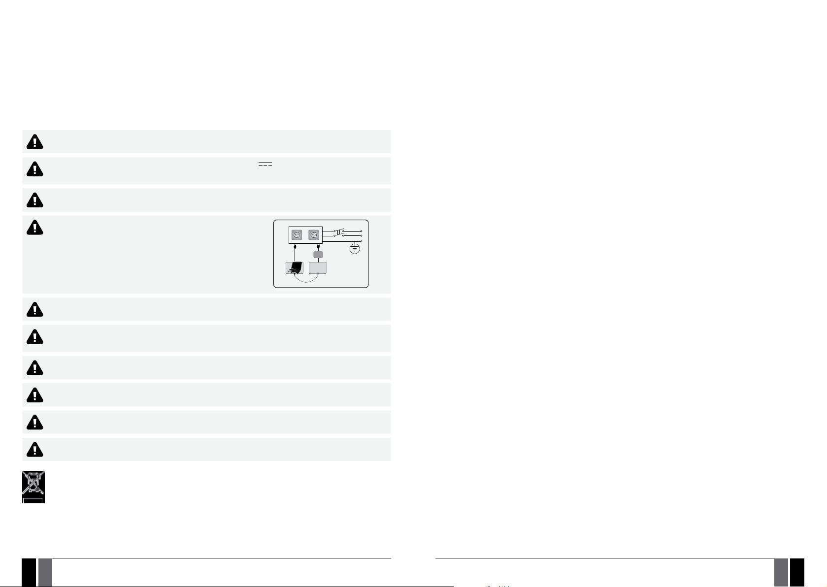
System Installation in ME1 Metal Cabinet
1. ME1 metal cabinet components
14
to AC main power line
Null
PE
Phase
Fuse 1A
(Primary voltage: 230V AC,
Secondary voltage: 17V 2,35A)
Transformer
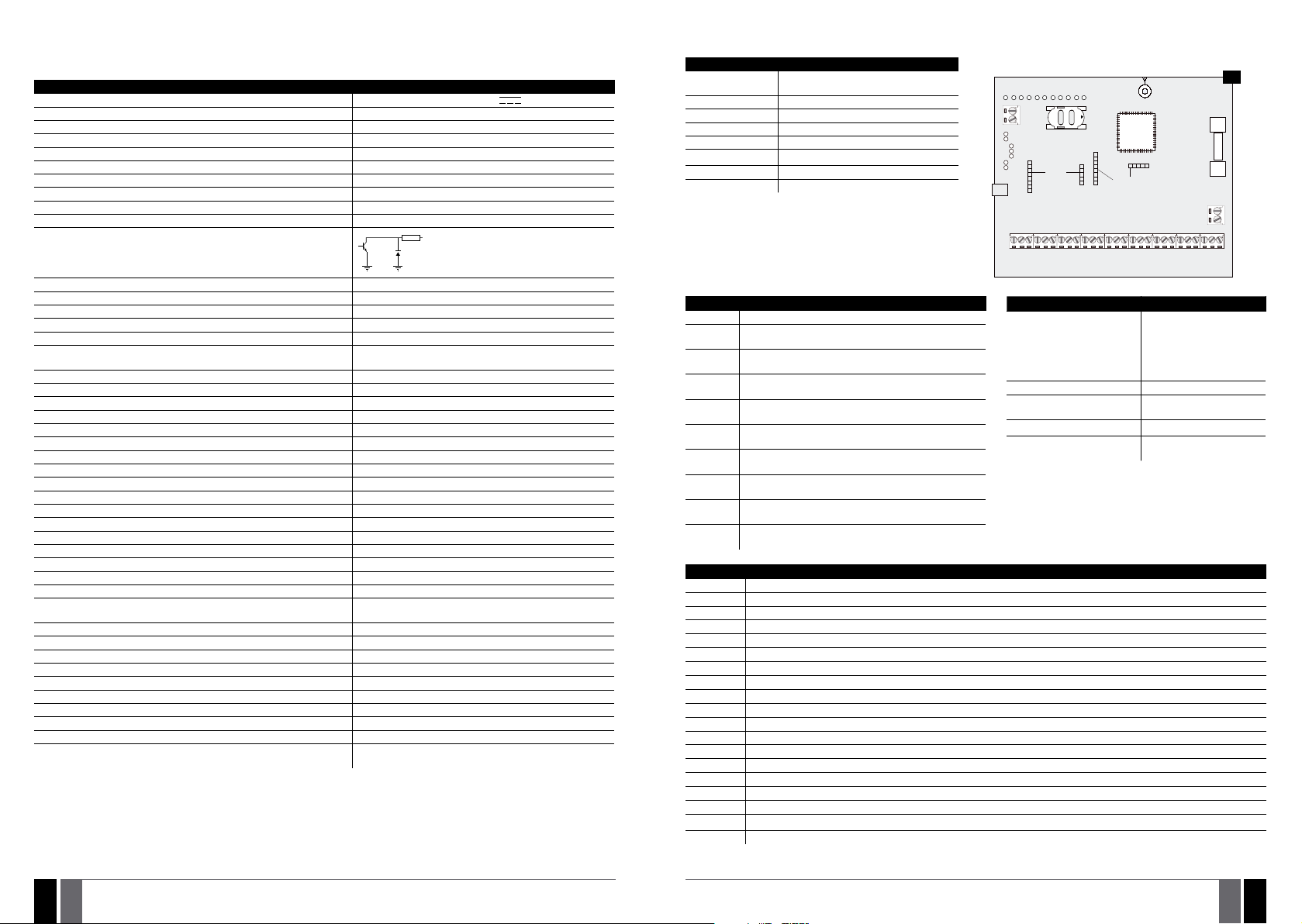
2. Insert the plastic standos into the appropriate mounting points and x the board of ESIM264 on the holders as indicated below.
2
(3x0.03in2) 1 thread double isolated cable. 230V power supply cables must
2
(2x0.03in2) 1 thread unshielded cable of up to 100m (328.08ft)
blue
brown
Tamper switch
to AC/DC terminals
of ESIM264 system
16
7
3. If EPGM1 module is to be installed, please install it in the rst place and ESIM264 alarm system afterwards. EPGM1 must be mounted on
the shorter plastic standos, while ESIM264 – on the longer ones. The mounting points of EPGM1 module are indicated below.
17
mounting
points*
15
18
1819EN
mounting points
* The standard ME1 metal cabinet does NOT contain the mounting points intended for EPGM1 module mounting, therefore it will be nec-
essary to drill out the mounting points by yourself.
MANUAL ELDES ESIM264 V3.2 MANUAL ELDES ESIM264 V3.2
19
EN
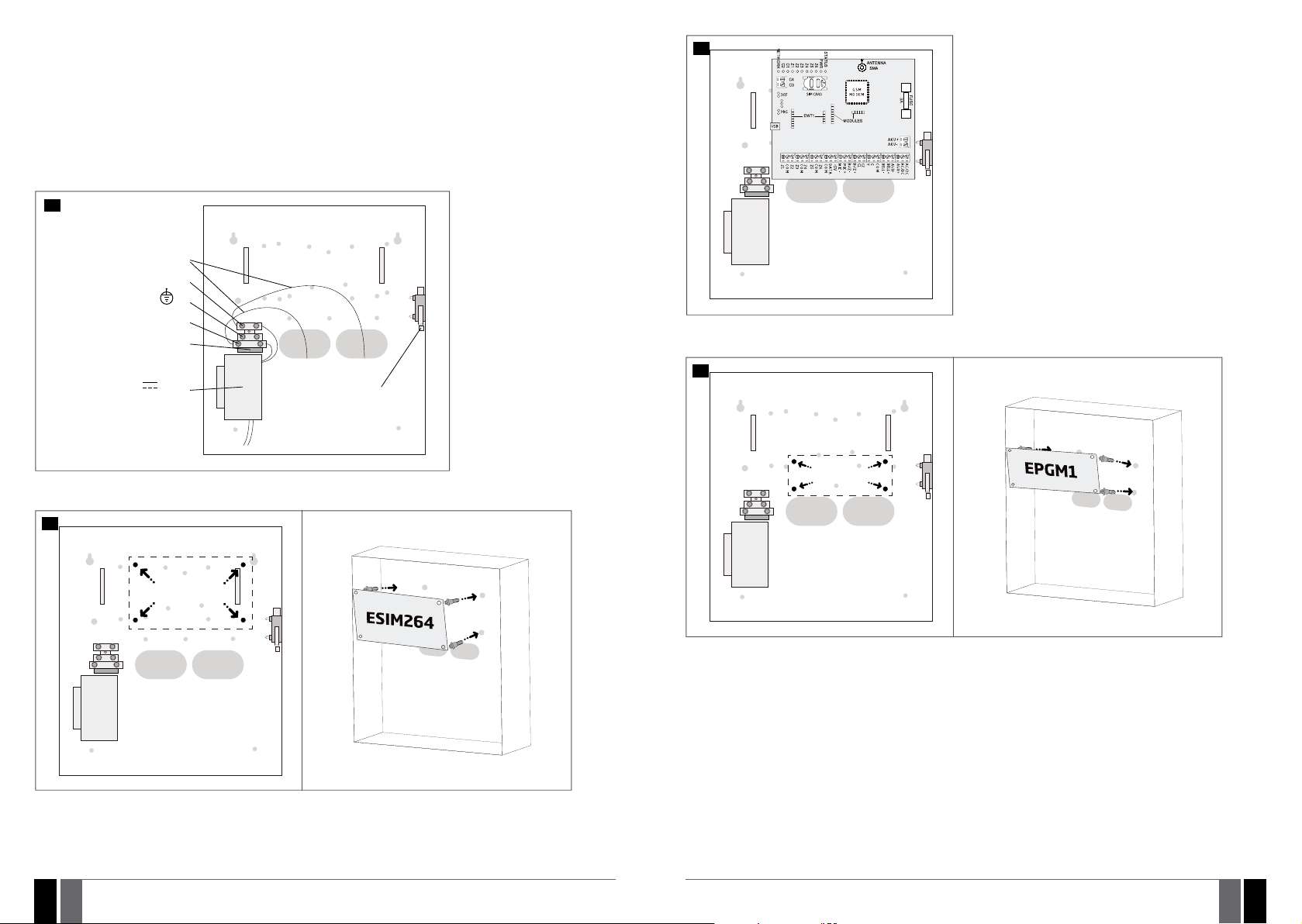
18
19
7
4. Wire up the accessories, such as keypads, zone and PGM output expansion modules, temperature sensor according to the wiring dia-
grams. Install the buzzer closer to iButton key reader in order to hear the exit delay countdown (see 2.3 Wiring Diagrams for more
details).
5. Disable the PIN code of the SIM card by inserting it into a mobile phone and following the proper menu steps. Ensure that the addition
al services, such as voice mail, call forwarding, report on missed/busy calls are disabled on the SIM card. For more details on how
to disable these services, please contact your GSM operator.
6. Once the PIN code is disabled, place the SIM card into the SIM CARD slot of the alarm system.
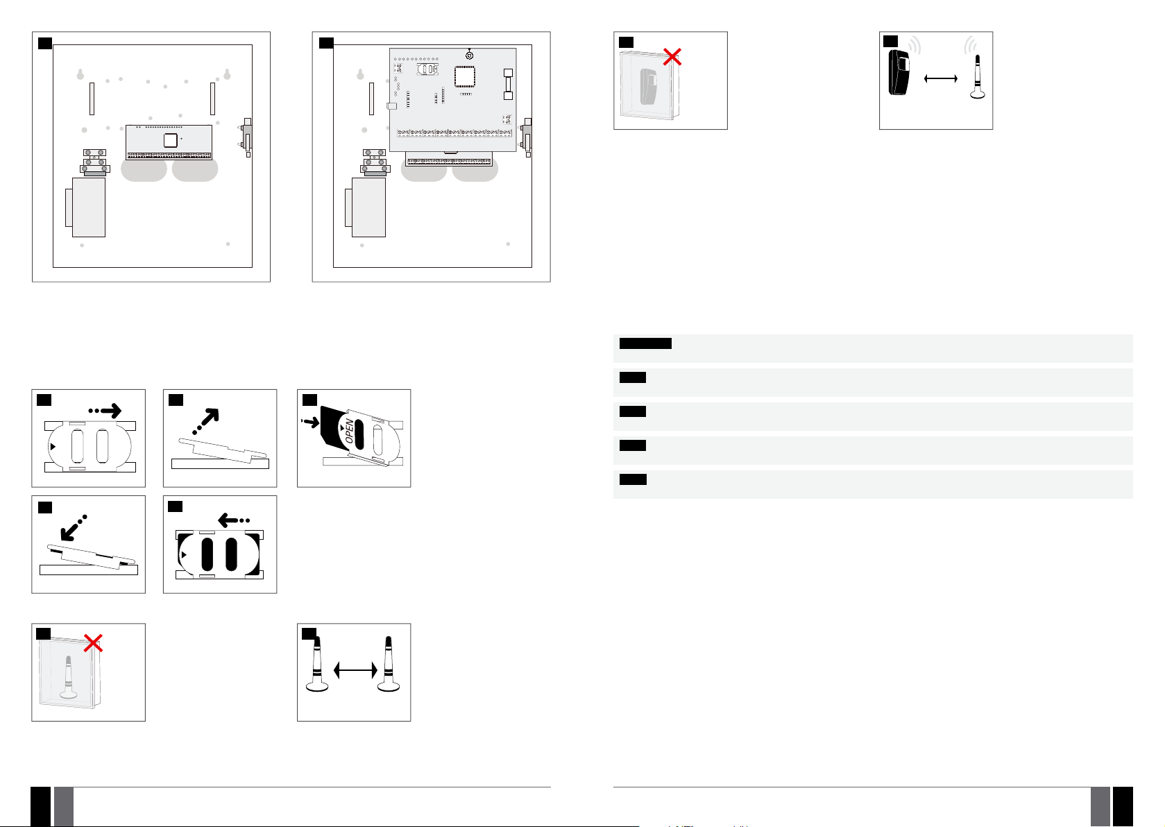
20
21
22
OPEN
27
Never install in the
following locations:
• inside the metal cabinet
• keep the distance of at least
Wireless
device
For more details on how to install the wireless devices, please refer to RADIO SYSTEM INSTALLATION AND SIGNAL PENETRATION
manual located at www.eldes.lt/download
20cm (7.87in) or more.
28
Wireless
device
0.5 m to 30 m
(1.64 to 98.43ft)
inside the building
0.5 m to 150 m
(1.64 to 492.13ft)
in open areas
Wireless
antenna
Recommended installation:
• face the front side of the
wireless device towards the
antenna
• keep the distance: 0,5 to 30m
(1.64 to 98.43ft) inside the
building, 0,5 to 150m (1.64 to
492.13ft) in open areas
9. Power up the system.
10. The system starts up in less than a minute. Indicator STATUS should be ashing indicating successful micro-controller operation.
11. The illuminated indicator NETWORK indicates that the system successfully registered to GSM network. To nd the strongest GSM sig-
nal, place the GSM/GPRS antenna and follow the indications provided by NETWORK indicator (see 2.3. Main Unit, LED and Connector
Functi onality).
12. Change the default SMS password (see 6. PASSWORDS for more details).
13. Set the phone number for User 1 (see 8. USER PHONE NUMBERS for more details).
14. Set system date and time (see 9. DATE AND TIME for more details).
15. Once the system is fully congured, it is ready for use. However, if you fail to receive an SMS reply from the system, please check the
SMSC (Short Message Service Center) phone number. For more details regarding the SMS centre phone number, please refer to 27.1.
SMSC (Short Message Service Center) Phone Number.
ATTENTION: The system is NOT compatible with pure 3G SIM cards. Only 2G/GSM SIM cards and 3G SIM cards with 2G/GSM prole enabled
are supported. For more details, please contact your GSM operator.
NOTE: The installation of iButton key reader, EKB2/EKB3 keypad, EWK1/EWK2 wireless keyfob is not mandatory. However, it is recommend-
ed to have those devices installed as an emergency switch in case your mobile phone is switched o or missing.
NOTE: For maximum system reliability we recommend you do NOT use a Pay As You Go SIM card. Otherwise, in the event of insucient
credit balance on the SIM card, the system would fail to make a phone call or send messages.
NOTE: We advise you to choose the same GSM SIM provider for your system as for your mobile phone. This will ensure the fastest, most
reliable SMS text message delivery service and phone call connection.
23
24
OPEN
7. Connect the GSM/GPRS and wireless antennas and follow the recommendations for the installation:
25
GSM/
GPRS
and/or
wireless
antenna
Never install in the
following locations:
• inside the metal cabinet
• keep the distance of at least
20cm (7.87in) or more.
26
20cm (7.87in)
GSM/GPRS
antenna
or more
Wireless
antenna
8. If one or more wireless devices are to be paired, follow the recommendations for the installation to achieve the strongest wireless signal:
20
2021EN
Recommended installation:
• keep the distance of at least
20cm (0.66ft) or more.
MANUAL ELDES ESIM264 V3.2 MANUAL ELDES ESIM264 V3.2
NOTE: Even though alarm system ESIM264 installation process is not too complicated, we still recommend to perform it by a person
with basic knowledge in electrical engineering and electronics to avoid any system damage.
EN
21

4. GENERAL OPERATIONAL DESCRIPTION
5. CONFIGURATION METHODS
When the system is being armed, it will initiate the exit delay countdown intended for the user to leave the secured area. During the
countdown period the buzzer will emit short beeps and/or LED indicator will ash. By default, exit delay duration is 15 seconds. After the
countdown is complete, the system will become armed and lock the conguration by keypad possibility. In case the user does not leave the
secured area before the countdown is complete, the system will arm in Stay mode if at least 1 zone has Stay attribute enabled. By default,
if there is at least 1 violated zone or tamper, the user will not be able to arm the system until the violated zone or tamper is restored. In case
it is required to arm the alarm system despite the violated zone presence, the violated zone can be bypassed or Force attribute enabled.
After the system is armed and if a zone (depending on type) or tamper is violated, the system will cause an alarm lasting for 1 minute (by
default), During the alarm, the siren/bell will provide an alarm sound along with the buzzers of the keypads. By default, the system will also
makes a phone call and send an SMS text message containing the violated zone or tamper number to a listed user and indicate the violated
zone or tamper number on the keypad. If another zone or tamper is violated or the same one is restored and violated again during the alarm,
the system will act as mentioned previously, but will not extend the alarm time.
After the user enters the secured area, the system will initiate the entry delay countdown intended for system disarming. During the countdown period, the buzzer will emit a steady beep and/or LED indicator will light ON. By default, entry delay duration is 15 seconds. After the
user successfully performs the disarming process, the system will unlock the keypads. If the user does not disarm the system in time, the
alarm system will cause an instant alarm.
NOTE: The alarm will be caused even if a tamper is violated while the system is disarmed.
For more details, please refer to 12. ARMING AND DISARMING.
!!! In this installation manual the underscore character ”_” represents one space character. Every underscore character must
be replaced by a single space character. There must be no spaces or other unnecessary characters at the beginning and at
the end of the SMS text message.
5.1. SMS Text Messages
In order to congure and control the system by SMS text message, send the text command to the ESIM264 system phone
SMS
5.2. EKB2 LCD Keypad
EKB2
NOTE: Menu section CONFIGURATION is secured with administrator password. The default administrator password is 1470.
NOTE: The system can be congured using only one keypad at a time. Other connected keypads will be inactive while the menu section
CONFIGURATION is opened. The inactive EKB2 keypads will display
NOTE: The keypad will automatically exit the menu section CONFIGURATION and return to home screen view if 1 minute after the last
key-touch expires.
5.3. EKB3 LED Keypad
EKB3
NOTE: If you were not willing to activate Conguration mode, but accidentally typed in the * as the rst character, please press [*] key again
or wait for 10 seconds until the keypad buzzer will provide a long beep indicating that the typed in characters have been cancelled.
number from one of the listed user phone numbers. The structure of SMS text message consists of 4-digit SMS password
(the default SMS password is 0000 – four zeros), the parameter and value. For some parameters the value does not apply e. g.
STATUS. The variables are indicated in lower-case letters, while a valid parameter value range is indicated in
The system conguration and control by EKB2 keypad is carried out by navigating throughout the menu section list displayed
on LCD screen. To navigate in the menu path, touch ↓, ↑ keys to select the desired menu section and touch OK key to open the
selected section. To enter a required value, use 0... 9 keys and touch OK key for conrmation or cancel/go one menu section
back by touching ← key. The value can be typed in directly by touching 0... 9 keys while highlighting the desired menu section. EKB2 menu type is “circle”, therefore when the last section in the menu list is selected, you will be brought back to the
beginning of the list after touching the ↓ key. In this installation manual, the menu path is based on the EKB2 menu tree by
starting at home screen view (see 31.1.1.6. EKB2 Menu Tree ). The variables are provided in lower-case letters, while a valid
parameter value range is provided in brackets.
icon and CONFIGURATION MODE message.
The system conguration and control by EKB3 keypad is carried out by activating the Conguration mode using the administrator password (by default – administrator password is 1470) and entering a valid conguration command using the number
keys [0]... [9], [#] key for conrmation and [*] key to cancel the characters that are being entered. Alternatively, the user
can wait for 10 seconds until the keypad buzzer will provide a long beep indicating that the entered characters have been
cancelled. When typing in the characters, the indication of each pressed key is provided by short beep of keypad buzzer and
red indicators when the number keys [0]... [9] are being pressed. Some commands require [BYPS], [CODE] and [STAY] keys as
well. The structure of a standard conguration command is a combination of digits. The commands, which do not require the
Conguration mode being activated, are noted. The variables are provided in lower-case letters, while a valid parameter value
range is provided in brackets.
22
2223EN
Activate/deactivate
Conguration mode
The following table provides a list of EKB3 indications, which are relevant during Conguration mode.
Indication Description
Indicator ARMED ashing Conguration mode activated successfully.
Indicator SYSTEM ashing Valid parameter is entered and waiting for valid value to be entered.
1 long beep Non-existing command or invalid parameter value entered.
3 short beeps Command entered successfully.
NOTE: The system can be congured using only one keypad at a time. Other connected keypads will be inactive while the Congura-
tion mode is activated.
NOTE: Conguration mode will automatically deactivate if 1 minute after the last key-stroke expires.
MANUAL ELDES ESIM264 V3.2 MANUAL ELDES ESIM264 V3.2
EKB3
Enter administrator password:
* aaaa #
Value: aaaa – 4-digit administrator password.
Example: *1470#
23
EN

5.4. ELDES Conguration Tool Software
Cong
5.4.1. Remote Connection
ELDES Conguration Tool software provides remote system conguration ability via Internet using one of the following methods:
• ELDES proxy server (recommended). The connection can be established on the system via GPRS network.
• Running TCP/IP server on ELDES Conguration Tool (advanced). The connection can be established on the system via GPRS network.
In order to start using the remote conguration feature, please run the step-by-step wizard and follow the steps provided in the start page
of ELDES Conguration Tool software. Please, note that it will be necessary to send an SMS text message to the system’s phone number
in order to initiate the remote connection. By following the steps you will be instructed on what text must be sent to the system’s phone
number in such case.
5.4.2. Ending the Remote Connection Session
Software ELDES Conguration Tool is intended for ESIM264 alarm system conguration via USB port locally or via GPRS con-
nection remotely. This software simplies system conguration process by allowing to use a personal computer in the process.
Tool
Before starting to use ELDES Conguration Tool software, please read the user guide provided in the software’s HELP section.
ELDES Conguration Tool is freeware and can be downloaded from at: www.eldes.lt
ATTENTION: The system will NOT send any data to monitoring station while conguring the system remotely via GPRS network. However,
during the conguration session, the data messages are queued up and transmitted to the monitoring station after the conguration session
is over.
ATTENTION: When the Conguration mode is activated by EKB3 keypad or menu section CONFIGURATION is opened by EKB2 keypad, re-
mote system conguration will be disabled.
NOTE: The keypads will be inactive when the system is being congured remotely.
6. PASSWORDS
For security reasons, the system uses the following types of passwords:
• SMS password – 4-digit password used for system arming/disarming and conguration by SMS text messages. By default, SMS pass-
word is 0000, which MUST be changed!
• Administrator password – 4-digit password used for Conguration mode activation by keypad and logging in to ELDES Conguration
Tool software. By default, Administrator password is 1470, which is highly recommended to change.
SMS text message content:
wwww_PSW_ssss
Set SMS password
SMS
EKB2
EKB3
Cong
Tool
Value: wwww – 4-digit default SMS password; ssss – 4-digit new SMS password; range –
[0001... 9999].
Example: 0000_PSW_1111
Menu path:
OK → CONFIGURATION → OK → aaaa → OK → PRIMARY SETTINGS → OK → PASSWORDS
→ OK → SMS PASSWORD → OK → ssss → OK
Value: aaaa – 4-digit administrator password; ssss – 4-digit new SMS password; range –
[0001... 9999].
Enter parameter 14 and new SMS password:
14 ssss #
Value: ssss – 4-digit new SMS password; range – [0001... 9999].
Example: 141111#
This operation may be carried out from the PC using the ELDES Conguration Tool software.
Terminate the
connection
with server
Once the session is expired or terminated, the system will reply with an SMS text message conrming the end of the session.
After the system conguration is complete, use one of the following methods to end the conguration
process:
• Click Disconnect or Stop button and close ELDES Conguration Tool software.
• The session will automatically expire in 20 minutes. Before the last 5 minutes, the software will oer
the user to extend the session for another 20 minutes.
• Alternatively, the connection with the server can be terminated at any time by sending an SMS text
message.
SMS text message content:
ssss_ENDCONFIG
SMS
Value: ssss – 4-digit SMS password.
Example: 1111_ENDCONFIG
Set Administrator
password
EKB2
EKB3
Cong
Tool
Menu path:
OK → CONFIGURATION → OK → 1470 → OK → PRIMARY SETTINGS → OK → PASSWORDS
→ OK → ADMIN PASSWORD → OK → aaaa → OK
Value: aaaa – 4-digit new administrator password; range – [0000... 9999].
Enter parameter 16 and new administrator password:
16 aaaa #
Value: aaaa – 4-digit new administrator password; range – [0000... 9999].
Example: 162538#
This operation may be carried out from the PC using the ELDES Conguration Tool software.
24
2425EN
MANUAL ELDES ESIM264 V3.2 MANUAL ELDES ESIM264 V3.2
25
EN

7. SYSTEM LANGUAGE
8. USER PHONE NUMBERS
The system comes equipped with 2 languages for communication with the user by SMS text messages and a single language for EKB2
keypad menu display. The default EKB2 menu language depends on ESIM264 rmware, which is based on the user’s location, while one of
languages for communication by SMS text messages is always English.
List of currently available system languages (rmwares):
• Czech
• English
• Estonian
• Finnish
• French
• Greek
• Hungarian
• Icelandic
• Italian
• Latvian
• Lithuanian
• Norwegian
• Portuguese
• Romanian
• Russian
• Slovak
• Spanish
• Swedish
To set a dierent SMS language, please refer to the following conguration methods.
SMS text message content:
ll
Set SMS language
NOTE: To obtain a rmware that features a dierent SMS and EKB2 menu language, please contact your local dealer.
NOTE: To change the language once the system has already been congured, you need to reset the device to the default conguration. For
more details on how to do this, please refer to 35.2. Restoring Default Parameters.
SMS
Value: ll - SMS language, range - [CZ - Czech, EN - English, EE - Estonian, FI - Finnish, GR -
Greek, HU - Hungarian, IC - Icelandic, IT - Italian, LV - Latvian, LT - Lithuanian, NO - Norwegian,
PT - Portuguese, RO - Romanian, RU - Russian, SK - Slovak, SP - Spanish, SW - Swedish].
Example: SK
Menu path:
OK → CONFIGURATION → OK → 1470 → OK → PRIMARY SETTINGS → OK → SMS LANGUAGE
EKB2
→ OK → sms-lang → OK
Value: sms-lang – SMS language.
The system supports up to 5 user phone numbers identied as User 1 through 5. When the phone number is set, the user will be able to
arm/disarm the system by SMS text messages and free of charge phone calls (see 12.1. Free of Charge Phone Call and 12.2. SMS Text
Message) as well as to congure the system by SMS text messages. User phone numbers are also used to receive alarm phone calls and
SMS text messages from the system (see 17. ALARM INDICATIONS AND NOTIFICATIONS FOR USER).
By default, the system accepts incoming calls and SMS text messages from any phone number. Once a user phone number is listed, the
system ignores any incoming calls and SMS text messages from a non-listed phone number as well as it rejects the SMS text messages
containing wrong SMS password even from a listed user phone number (see 8.1. System Control from any Phone Number). To set User
1 phone number is mandatory, while the other 4 are optional. The supported phone number format is the following:
• International (w/o plus) – The phone numbers must be entered starting with an international country code in the following for-
mat: [international code][area code][local number], example for UK: 4417091111111.
SMS text message content:
Set user phone
number
View user phone
number
Cong
ssss_NRup:ttteeellnnuumm
SMS
Value: ssss – 4-digit SMS password; up – user phone number slot, range – [1... 5]; ttteeelln-
nuumm – up to 15 digits user phone number.
Example: 1111_NR1:44170911XXXX1
Menu path:
OK → CONFIGURATION → OK → aaaa → OK → PRIMARY SETTINGS → OK → CALL/SMS SETTINGS
EKB2
→ OK → USERS → OK → USER 1... 5 → OK → PHONE NUMBER → OK → ttteeellnnuumm → OK
Value: aaaa – 4-digit administrator password; ttteeellnnuumm – up to 15 digits user phone
number.
Enter parameter 17, user phone number slot and phone number:
17 up ttteeellnnuumm #
EKB3
Value: up – user phone number slot, range – [01... 05]; ttteeellnnuumm – up to 15 digits user
phone number.
Example: 170144170911XXXX1#
This operation may be carried out from the PC using the ELDES Conguration Tool software.
Tool
SMS text message content:
ssss_HELPNR
SMS
Value: ssss – 4-digit SMS password.
Example: 1111_HELPNR
Menu path:
OK → CONFIGURATION → OK → aaaa → OK → PRIMARY SETTINGS → OK → CALL/SMS
EKB2
SETTINGS → OK → USERS → OK → USER 1... 5 → OK → PHONE NUMBER → PHONE NUMBER
Value: aaaa – 4-digit administrator password.
26
2627EN
Delete user phone
number
MANUAL ELDES ESIM264 V3.2 MANUAL ELDES ESIM264 V3.2
Cong
Tool
SMS
EKB2
Cong
Tool
This operation may be carried out from the PC using the ELDES Conguration Tool software.
SMS text message content:
ssss_NRup:DEL
Value: ssss – 4-digit SMS password; up – user phone number slot, range – [2... 5].
Example: 1111_NR2:DEL
Menu path:
OK → CONFIGURATION → OK → aaaa → OK → PRIMARY SETTINGS → OK → CALL/SMS
SETTINGS → OK → USERS → OK → USER 2... 5 → OK → PHONE NUMBER → OK → OK
Value: aaaa – 4-digit administrator password.
This operation may be carried out from the PC using the ELDES Conguration Tool software.
EN
27

ATTENTION: NEVER add a phone number of the device’s SIM card as a user phone number!
ATTENTION: Once User 1 phone number is set, it will be restricted to modify it only.
NOTE: Multiple user phone numbers can be set by a single SMS text message, Example: 1111_NR1:44170911XXXX1_
NR2:44170911XXXX2_ NR5:44170911XXXX3
NOTE: Multiple user phone numbers can be deleted by a single SMS text message, Example: 1111_NR2:DEL_NR3:DEL
8.1. System Control from any Phone Number
By default, once a user phone number is listed, the system ignores any incoming calls and SMS text messages from a non-listed phone
number as well as it rejects the SMS text messages containing wrong SMS password even from a listed user phone number. To permit/deny
system arming/disarming by phone call and SMS text message that contain a valid SMS password, conguration by SMS text message that
contain a valid SMS password from any phone number, please refer to the following conguration methods.
Enable system control
from any phone
number
Cong
SMS text message content:
ssss_STR:ON
SMS
Value: ssss – 4-digit SMS password.
Example: 1111_STR:ON
Menu path:
OK → CONFIGURATION → OK → aaaa → OK → PRIMARY SETTINGS → OK → CALL/SMS
EKB2
SETTINGS → OK → CTRL FROM ANY NUM → OK → ENABLE → OK
Value: aaaa – 4-digit administrator password.
Enter parameter 12 and parameter status value:
12 1 #
EKB3
Example: 121#
This operation may be carried out from the PC using the ELDES Conguration Tool software.
Tool
9. DATE AND TIME
The system comes equipped with internal real-time clock (RTC) that keeps track of the current date and time. Once the system is up and
running, the user must set the correct date and time, otherwise the system will not operate properly. After shutting down and starting up
the system, the date and time must be set again.
SMS text message content:
ssss_yyyy.mm.dd_hr:mn
Set date and time
NOTE: When the system is connected to the monitoring station via GPRS network connection, the date and time will be automatically
synchronized with the monitoring station upon the system startup.
SMS
EKB2
EKB3
Cong
Tool
Value: ssss – 4-digit SMS password; yyyy – year; mm – month, range – [01... 12]; dd – day,
range – [01... 31]; hr – hours, range – [00... 23]; mn – minutes, range – [00... 59].
Example: 1111_2015.03.16_14:33
Menu path:
a) OK → DATE/TIME SETTINGS → OK → yyyy-mm-dd hr:mn → OK
b) OK → CONFIGURATION → OK → aaaa → OK → PRIMARY SETTINGS → OK → DATE/TIME
SETTINGS → OK → yyyy-mm-dd hr:mn → OK
Value: aaaa – 4-digit administrator password; yyyy – year; mm – month, range – [01... 12];
dd – day, range – [01... 31]; hr – hours, range – [00... 23]; mn – minutes, range – [00... 59].
Enter parameter 66, date and time:
66 yyyy mm dd hr mn#
Value: yyyy – year; mm – month, range – [01... 12]; dd – day, range – [01... 31]; hr – hours,
range – [00... 23]; mn – minutes, range – [00... 59].
Example: 66201505291235#
This operation may be carried out from the PC using the ELDES Conguration Tool software.
Disable system
control from any
phone number
28
2829EN
SMS
EKB2
EKB3
Cong
Tool
SMS text message content:
ssss_STR:OFF
Value: ssss – 4-digit SMS password.
Example: 1111_STR:OFF
Menu path:
OK → CONFIGURATION → OK → aaaa → OK → PRIMARY SETTINGS → OK → CALL/SMS
SETTINGS → OK → CTRL FROM ANY NUM → OK → DISABLE → OK
Value: aaaa – 4-digit administrator password.
Enter parameter 12 and parameter status value:
12 0 #
Example: 120#
This operation may be carried out from the PC using the ELDES Conguration Tool software.
MANUAL ELDES ESIM264 V3.2 MANUAL ELDES ESIM264 V3.2
29
EN

10. USER CODES
The system supports up to 30 numeric user codes, identied as User Code 1 through 30, allowing to carry out system arming/disarming by
the keypad. By default, User Code 1 is listed as 1111 and assigned to Partition 0. For more details regarding user code partition, please refer
to 23.4. User Code Partition.
Menu path:
User code 1... 16: OK → CONFIGURATION → OK → aaaa → OK → PRIMARY SETTINGS →
Set user code
Delete user code
EKB2
EKB3
Cong
Tool
EKB2
EKB3
Cong
Tool
OK → PASSWORDS → OK → USER PASSWORDS → OK → USER PSW (1-16) → OK → USER
PASSWORD 1... 16 → OK → PASSWORDS → OK → uuuu → OK
User code 17... 30: OK → CONFIGURATION → OK → aaaa → OK → PRIMARY SETTINGS →
OK → PASSWORDS → OK → USER PASSWORDS → OK → USER PSW (17-30) → OK → USER
PASSWORD 17... 30 → OK → PASSWORDS → OK → uuuu → OK
Value: aaaa – 4-digit administrator password; uuuu – 4-digit user code, range – [0000...
9999].
Enter parameter 15, user code slot and user code:
15 us uuuu #
Value: us – user code slot, range – [01... 30]; uuuu – 4-digit user code; range – [0000... 9999].
Example: 15021111#
This operation may be carried out from the PC using the ELDES Conguration Tool software.
Menu path:
OK → CONFIGURATION → OK → aaaa → OK → PRIMARY SETTINGS → OK → PASSWORDS →
OK → USER PASSWORDS → OK → REMOVE PASSWORD → OK → uuuu → OK
Value: aaaa – 4-digit administrator password; uuuu – 4-digit user code.
Enter parameter 65 and user code:
65 uuuu #
Value: uuuu – 4-digit user code.
Example: 651111#
This operation may be carried out from the PC using the ELDES Conguration Tool software.
One of the user codes ranging from User Code 1 through 10 can be set as SGS (Security Guard Service) code, which is used as a checkpoint
by a security service guard upon his/her visit in the secured location. When used, a data message, containing a certain event code, will be
delivered to the monitoring station. However, NO system arming or disarming will be carried out after entering the SGS password.
Menu path:
OK → CONFIGURATION → OK → aaaa → OK → PRIMARY SETTINGS → OK → PASSWORDS →
Set SGS code
The Duress code is used when system arming or disarming is demanded by force. When used, the system will arm/disarm as well as it will silently transmit an alert to the monitoring station. Only one of the user code ranging from User Code 1 through 10 can be set as Duress code.
Set Duress code
EKB2
EKB3
Cong
Tool
EKB2
EKB3
Cong
Tool
OK → USER PASSWORDS → OK → SGS PASSWORD → OK → N/A / us → OK
Value: aaaa – 4-digit administrator password; N/A – SGS code not in use; us – user code
slot, range – [1... 10].
Enter parameter 74 and user code slot:
74 us #
Value: us – user code slot, range – [01... 10].
Example: 7403#
This operation may be carried out from the PC using the ELDES Conguration Tool software.
Menu path:
OK → CONFIGURATION → OK → aaaa → OK → PRIMARY SETTINGS → OK → PASSWORDS →
OK → USER PASSWORDS → OK → DURESS PASSWORD → OK → N/A / us → OK
Value: aaaa – 4-digit administrator password; N/A – Duress password not in use; us – user
code slot, range – [1... 10].
Enter parameter 73 and user code slot:
73 us #
Value: us – user code slot, range – [01... 10].
Example: 7309#
This operation may be carried out from the PC using the ELDES Conguration Tool software.
Menu path:
User code 1... 16: OK → CONFIGURATION → OK → aaaa → OK → PRIMARY SETTINGS →
Replace user code
NOTE: The system does not allow to set a duplicate password
30
3031EN
EKB2
EKB3
Cong
Tool
OK → PASSWORDS → OK → USER PASSWORDS → OK → USER PSW (1-16) → OK → USER
PASSWORD 1... 16 → OK → PASSWORD → OK → uuuu → OK
User code 17... 30: OK → CONFIGURATION → OK → aaaa → OK → PRIMARY SETTINGS →
OK → PASSWORDS → OK → USER PASSWORDS → OK → USER PSW (17-30) → OK → USER
PASSWORD 17... 30 → OK → PASSWORD → OK → uuuu → OK
Value: aaaa – 4-digit administrator password; uuuu – 4-digit user code, range – [0000...
9999].
Enter parameter 63, existing user code and new user code:
63 vvvv uuuu #
Value: vvvv – 4-digit existing user code; uuuu – 4-digit new user code, range – [0000...
9999].
Example: 6311113254#
This operation may be carried out from the PC using the ELDES Conguration Tool software.
MANUAL ELDES ESIM264 V3.2 MANUAL ELDES ESIM264 V3.2
31
EN
11. iBUTTON KEYS
When adding of iButton keys is complete, please disable Allow Adding New iButton Keys mode.
An iButton key is a unique 64-bit ID code containing chip enclosed in a stainless steel tab usually implemented in a small plastic holder.
ESIM264 system supports up to 5 iButton keys each holding a unique identity code (ID), which is used for system arming and disarming.
11.1. Adding and Removing iButton Keys
NOTE: iButton Key 1 can be added without Allow Adding New iButton Keys mode being enabled.
To add an iButton key to the system, do the following:
a) Disarm the system in all partitions (see 12. ARMING AND DISARMING).
b) Enable Allow Adding New iButton Keys mode.
c) T ouch the key to the iButton key reader when the system is disarmed (see picture below).
29
d) The successfully added iButton key will be indicated by short beeps emitted by the system’s buzzer.
e) Add as many iButton keys as necessary – touch one key after another to the reader – until the number of 5 keys is reached.
Enable Allow Adding
New iButton Keys
mode
Cong
SMS text message content:
ssss_IBPROG:ON
SMS
Value: ssss – 4-digit SMS password.
Example: 1111_IBPROG:ON
Menu path:
OK → CONFIGURATION → OK → aaaa → OK → IBUTTON KEYS → OK → NEW IBUTTON →
EKB2
OK → ENABLE → OK
Value: aaaa – 4-digit administrator password.
Enter parameter 18 and parameter status value:
18 0 #
EKB3
Example: 180#
This operation may be carried out from the PC using the ELDES Conguration Tool software.
Tool
Disable Allow Adding
New iButton Keys
mode
Cong
To view the ID of the added iButton keys, please refer to the following conguration methods.
View iButton key ID
Cong
If the iButton key is lost or stolen, due to security reasons it is highly recommended to remove it from the system.
Remove individual
iButton key from the
system
Cong
Remove all iButton
keys from the system
SMS text message content:
ssss_IBPROG:OFF
SMS
Value: ssss – 4-digit SMS password.
Example: 1111_IBPROG:ON
Menu path:
OK → CONFIGURATION → OK → aaaa → OK → IBUTTON KEYS → OK → NEW IBUTTON →
EKB2
OK → DISABLE → OK
Value: aaaa – 4-digit administrator password.
Enter parameter 18 and parameter status value:
18 1 #
EKB3
Example: 181#
This operation may be carried out from the PC using the ELDES Conguration Tool software.
Tool
Menu path:
OK → CONFIGURATION → OK → aaaa → OK → IBUTTON KEYS → OK → IBUTTON 1... 5 → OK
EKB2
→ ID
Value: aaaa – 4-digit administrator password.
This operation may be carried out from the PC using the ELDES Conguration Tool software.
Tool
Menu path:
OK → CONFIGURATION → OK → aaaa → OK → IBUTTON KEYS → OK → IBUTTON 1... 5 → OK
EKB2
→ REMOVE → OK
Value: aaaa – 4-digit administrator password.
This operation may be carried out from the PC using the ELDES Conguration Tool software.
Tool
SMS text message content:
ssss_RESETIB
SMS
Value: ssss – 4-digit SMS password.
Example: 1111_RESETIB
32
3233EN
MANUAL ELDES ESIM264 V3.2 MANUAL ELDES ESIM264 V3.2
33
EN

12. ARMING AND DISARMING
The system features the following methods to carry out arming and disarming process:
• Free of charge phone call.
• SMS text message.
• EKB2/EKB3 keypad and user code.
• iButton key.
• EWK1/EWK2 wireless keyfob.
• Arm-Disarm by Zone.
• EGR100 middle-ware.
The system arms/disarms the partitions that the listed user phone number, EKB2/EKB3 keypad and user code, iButton key, EWK1 wireless
keyfob or zone, set up for Arm-Disarm by Zone method, are assigned to. For example, if User 1 phone number is assigned to Partition 0, the
user will be able to arm/disarm Partition 0 by a single phone call to the system (see 23. PARTITIONS).
By default, when the system is successfully armed or disarmed, it replies with conrmation by SMS text message. For more details on SMS
text message regarding system arming/disarming and how to manage it, please refer to 12.9. Disabling and Enabling Arm/Disarm
Notications.
The system will allow to arm the system if the following system faults are present (see 29. INDICATION OF SYSTEM FAULTS):
• Mains power is lost.
• Low battery.
• Battery failed.
• Date/time not set.
• GSM connection failed.
In case of violated zone/tamper presence when attempting to arm the system by free of charge phone call, SMS text message, iButton key
and Arm-Disarm by Zone method, the system will reply with SMS text message containing violated zone/tamper number. Due to security reasons it is highly recommended to restore the violated zone/tamper before arming the system. For more details on how to arm the
system regardless of the violated zone presence, please refer to 14.6. Zone Attributes and 14.7. Bypassing and Activating Zones.
Once a user phone number is listed, the system ignores any incoming calls and SMS text messages from a non-listed phone number as well
as it rejects the SMS text messages containing wrong SMS password even from a listed user phone number. For more details regarding
arming/disarming the system from a non-listed phone number, please refer to 8.1. System Control from any Phone Number.
12.1. Free of Charge Phone Call
To arm and disarm the system, dial the system‘s phone number from any of 5 available user phone numbers (see 8. USER
PHONE NUMBERS for user phone number management). The phone call is free charge as the system rejects it and carries out
arming/disarming procedure afterwards. When arming – the system rejects the phone call after 2 rings, when disarming – the
system rejects the phone call immediately. If there is more than one listed user dialling to the system at the same time, the
system will accept the incoming call from the user who was the rst to dial while other user (-s) will be ignored.
The system will arm/disarm the partition corresponding to the one that the user phone number is assigned to. For more details on how to
set user phone number partition, please refer to 23.2. User Phone Number Partition.
30
12.2. SMS Text Message
To arm the system by SMS text message, send the following text to the system‘s phone number from any of 10 available user
phone numbers (see 8. USER PHONE NUMBERS for user phone number management). When the SMS text message for arm-
SMS
ing is sent to the system’s phone number, the system will proceed as follows:
• Non-partitioned system:
• If ready (no violated zone/tamper), the system will arm.
• If unready, the system will not arm and provide a list of violated zones/tampers by SMS text message to user phone
number.
• Partitioned system:
• If all partitions are disarmed ready (no violated zone/tamper), the system will arm them.
• If one or more partitions are disarmed unready (violated zone/tamper is present), the system will arm the ready partition (-s) and skip the unready one (-s). The system will then send an SMS text message, containing a list of violated
zones/tampers, to user phone number that the system arming was initiated from.
• If a combination of armed and disarmed ready partitions is present, the system will arm the disarmed ready partitions
and skip the armed ones.
SMS text message content:
Arm the system
To disarm the system by SMS text message, send the following text to the system‘s phone number from any of 10 available user phone numbers:
Disarm the system
ssss_ARMp or ssss_ARMp,p
Value: ssss – 4-digit SMS password; p – partition number, range – [1 – Partition 0, 2 – Partition 1].
Example: 1111_ARM1
31
SMS
User
SMS text message content:
ssss_DISARMp or ssss_DISARMp,p
Value: ssss – 4-digit SMS password; p – partition number, range - [1 – Partition 0, 2 – Partition 1].
Example: 1111_DISARM1,2
SMS
ESIM264
32
34
3435EN
User
CALL
ESIM264
Regardless of the partition a user phone number is assigned to, the user will be able arm/disarm by SMS text message method either Partition 0 , Partition 1 or both partitions simultaneously.
12.3. EKB2 Keypad and User Code
READY message displayed in the home screen view by EKB2 keypad indicates that no violated zones and/or tampers are pres-
EKB2
MANUAL ELDES ESIM264 V3.2 MANUAL ELDES ESIM264 V3.2
ent, therefore the system can be armed. If the message is displayed as NOT READY, the user must restore all violated zones
and tampers before arming the system. Alternatively, the violated zones can be bypassed (see 14.7. Bypassing and Activat-
ing Zones), disabled (see 14.9. Disabling and Enabling Zones) or a Force attribute enabled (see 14.6. Zone Attributes).
To arm the system by EKB2 keypad, enter any out of 30 available 4-digit user codes using the number keys on the keypad (see
10. USER CODES for user code management).
By default when a valid user code is entered, the system will initiate exit delay, the keypad’s buzzer will emit short beeps and
the keypad will display
icon for 5 seconds and switch to home screen view.
User
icon next to the countdown timer. When the system is successfully armed, the keypad will display
ESIM264
35
EN
 Loading...