

Eldes ESIM252 User Manual
ESIM252
GSM CONTROL SYSTEM
User Manual v2.1
Valid for ESIM252 v21.04.00 and up
SAFETY INSTRUCTIONS
Please read and follow these safety guidelines to safeguard yourself and others:
• GSM control system ESIM252 (later referred to as “the system” or “ the device”) contains a built-in radio transceiver operating in GSM
850/900/1800/1900 MHz bands.
• DO NOT use the system where it can cause potential danger and interfere with other devices – such as medical devices.
• DO NOT use the system in hazardous environment.
• DO NOT expose the system to high humidity, chemical environment or mechanical impact.
• DO NOT attempt to repair the system yourself – any repairs must be carried out by fully qualied personnel only.
Disconnect the mains power before installing. Never install or carry out maintenance during stormy weather. The electric
socket that powers the system must be easily accessible.
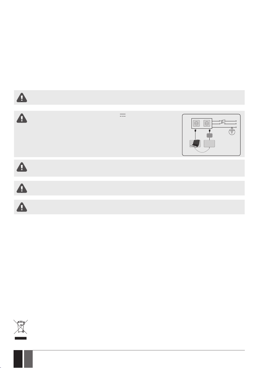
Please use the 10-24V 50Hz ~200mA AC or 10-24V 200mA DC power supply unit
that meets the EN 60950-1 standard. Any additional device you connect to the system,
such as a computer, must also be powered by an EN 60950-1 approved supply. When connecting the power supply to the system, switching the polarity terminal places does not
have any aect.
External power supply can be connected to AC mains only inside installation room with automatic 2-pole circuit breaker capable of disconnecting circuit in the event of short circuit or over-current condition. Open circuit breaker must have a gap between connections of more than 3mm (0.12in) and the disconnection current 5A.
To switch the system o, unplug the external electric power supply from or any other linked device that the system is powered
from
A blown fuse cannot be replaced by the user. The replacement fuse has to be of the kind indicated by the manufacturer (fuse
F1 model – MINISMDC050F 0.5A).
AC/DC
ESIM252
USB cable
AC 230V
50 Hz/DC 24V
Phase
Null
PE
The WEEE (Waste Electrical and Electronic Equipment) symbol on this product (see left) means it must not be disposed of in
household waste. To prevent possible harm to human health and/or the environment, you must dispose of this product in an
approved and environmentally safe recycling facility. For further information contact your system supplier, or your local waste
authority.
2
2 EN
ESIM252 User Manual v2.1

CONTENTS
1. GENERAL INFORMATION .........................................................................................................................................................5
2. TECHNICAL SPECIFICATIONS ...................................................................................................................................................5
2.1. Electrical and Mechanical Characteristics ..................................................................................................................................................... 5
2.2. Main Unit, LED Indicator and Connector Functionality ...............................................................................................................................6
2.3. Wiring Diagram ..................................................................................................................................................................................................7
3. INSTALLATION .........................................................................................................................................................................8
4. GENERAL OPERATIONAL DESCRIPTION ..................................................................................................................................9
5. CONFIGURATION METHODS ....................................................................................................................................................9
5.1. SMS Text Messages ...........................................................................................................................................................................................9
5.2. ELDES Conguration Tool ................................................................................................................................................................................9
6. SYSTEM LANGUAGE ...............................................................................................................................................................10
7. SMS PASSWORD .....................................................................................................................................................................10
8. USER PHONE NUMBERS ........................................................................................................................................................ 11
8.1. System Control from any Phone Number ....................................................................................................................................................12
9. DATE AND TIME ......................................................................................................................................................................13
10. INPUTS ...................................................................................................................................................................................13
10.1. Pulse Counter ...................................................................................................................................................................................................14
10.2. Disabling and Enabling Inputs ....................................................................................................................................................................... 14
11. ALARM/RESTORE NOTIFICATIONS ........................................................................................................................................16
11.1. Enabling and Disabling Alarm/Restore Notication Delivery to All Listed Users ................................................................................19
12. AUDIO FILES .......................................................................................................................................................................... 20
13. OUTPUTS............................................................................................................................................................................... 20
13.1. Output Names ................................................................................................................................................................................................. 20
13.2. Output Control by Free of Charge Phone Call .............................................................................................................................................21
13.3. Control by SMS Text Message ....................................................................................................................................................................... 24
13.4. Automatic Output Control ............................................................................................................................................................................. 26
14. SYSTEM INFORMATION. INFO SMS ....................................................................................................................................... 29
14.1. Periodic Info SMS ............................................................................................................................................................................................ 29
15. SYSTEM NOTIFICATIONS ...................................................................................................................................................... 30
15.1. SMSC (Short Message Service Center) Phone Number ............................................................................................................................ 30
16. EVENT LOG .............................................................................................................................................................................31
17. REMOTE LISTENING ...............................................................................................................................................................32
18. GPRS NETWORK SETTINGS ...................................................................................................................................................32
19. MONITORING STATION ...........................................................................................................................................................33
19.1. Data Messages - Events .................................................................................................................................................................................33
19.2. Communication ................................................................................................................................................................................................33
20. PROJECT EXAMPLES AND CONFIGURATION ..........................................................................................................................37
20.1. Using in Enterprises ........................................................................................................................................................................................37
20.2. Using in a Private House ............................................................................................................................................................................... 41
20.3. Using with Heating System and Flood Detector ....................................................................................................................................... 43
20.4. Using for Breakdown Reports ......................................................................................................................................................................45
21. TECHNICAL SUPPORT ........................................................................................................................................................... 48
21.1. Troubleshooting ............................................................................................................................................................................................. 48
21.2. Restoring Default Parameters ..................................................................................................................................................................... 48
21.3. Updating the Firmware via USB Cable ........................................................................................................................................................48
21.4. Updating the Firmware via GPRS Connection Remotely ......................................................................................................................... 49
22. RELATED PRODUCTS............................................................................................................................................................. 50
ESIM252 User Manual v2.1
3
3EN

Limited Liability
The buyer agrees that the system will reduce the risk of re, theft, burglary or other danger but that it does not guarantee against the occurrence of such events. “ELDES UAB” will not take any responsibility for the loss of personal eects, property or revenue whilst using the
system. The liability of “ELDES UAB” is limited to the value of the system purchased. “ELDES UAB” is not aliated with any mobile/wireless/
cellular provider and is therefore not responsible for the quality of such services.
Manufacturer Warranty
The system carries a 24-month manufacturer warranty from “ELDES UAB”. The warranty begins the day the system is purchased by the
user and the receipt must be retained as proof of purchase date. The warranty remains valid only if the system is used as intended, following all guidelines outlined in this manual and in accordance with the operating conditions specied. The warranty is void if the system
has been exposed to mechanical impact, chemicals, high humidity, uids, corrosive and hazardous environments or force majeure factors.
Dear Customer,
Thank you for choosing to purchase the GSM control system ESIM252. Your thoughtful decision will ensure reliable solution for many
years as all ELDES products are manufactured to meet the highest standards.
We are condent that you will be completely satised with your product. However, in the unlikely event that you do experience a problem, please contact the dealer from whom you made your purchase.
UAB ELDES
www.eldes.lt
CONTENTS OF PACK
Item Quantity
1. ESIM252 ...................................................1
2. User manual ............................................1
3. GSM/GPRS antenna ...............................1
4. Plastic standos ....................................4
Not included:
• SIM card – we recommend you get a contract SIM, not Pay As You Go.
• miniUSB cable – can be obtained from your local distributor.
• Microphone – can be obtained from your local distributor.
Copyright © “ELDES UAB”, 2015. All rights reserved
It is strictly forbidden to copy and distribute information in this document or pass to a third party without an advanced written authorization from “ELDES UAB”. “ELDES UAB” reserves the right to update or modify this document and/or related products without a
warning. Hereby, “ELDES UAB” declares that the GSM control system ESIM252 is in compliance with the essential requirements and
other relevant provisions of Directive 1999/5/EC. The declaration of conformity may be consulted at www.eldes.lt.
4
4 EN
ESIM252 User Manual v2.1

1. GENERAL INFORMATION
ESIM252 is a micro-controller based device intended to receive alarm/restore events by SMS text message or phone call and control an
electrical appliance via the GSM network.
Examples of using the system:
• Access control.
• Gate control of private houses.
• Notication of system events, such as arming/disarming, alarm/restore from non-GSM alarm system.
• Non-GSM alarm system arming/disarming by SMS text message.
• Any electrical appliance control: lighting, watering, heating etc.
• Remote reboot of the “frozen” systems, such as computer network or a server.
Main features:
• 5 inputs with customizable alarm/restore texts.
• Up to 5 user phone numbers for system conguration by SMS text messages, acceptance of input alarm/restore SMS text messages and
phone calls, output control by SMS text message and free of charge phone call.
• 2 relay outputs for electrical appliance control or non-GSM alarm system arming/disarming (key-switch).
• Manual output control by free of charge phone call.
• Automatic output control in accordance with the scheduled time.
• Up to 10 audio messages for input alarm/restore notication.
• Event log of 500 events.
• Periodic self-test notication by SMS text message to user phone number.
2. TECHNICAL SPECIFICATIONS
2.1. Electrical and Mechanical Characteristics
Supply voltage ..........................................................................................10-24V 50Hz ~ 200mA max / 10-24V 200mA max
Current used in idle state ........................................................................Up to 50mA
GSM modem frequency ...........................................................................850/900/1800/1900 MHz
Number of outputs ..................................................................................2
Output type...............................................................................................Relay; NO (normally-open)
Maximum commuting output values ....................................................24V 50Hz ~ 0,5A / 24V 1A
Number of “low” level (negative) inputs ..............................................4
Number of “high” level (positive) inputs ..............................................1
“Low” level (negative) input value range .............................................0... 16V -0.8... -0.4mA
“High” level (positive) input value range .............................................5... 50V 0.17 .... 1.7mA
“Low” level (negative) and “high” level (positive) ...............................NO (normally-open) / NC (normally-closed)
input connection type
Dimensions ...............................................................................................87x107x29mm (3.43x4.21x1.14in)
Operating temperature range ...............................................................-20…+55 °C (-4... +131°F )
Humidity ....................................................................................................0-90% RH @ 0... +40°C (0-90% RH @ +32... +104°F) (non-condensing)
ESIM252 User Manual v2.1
5
5EN
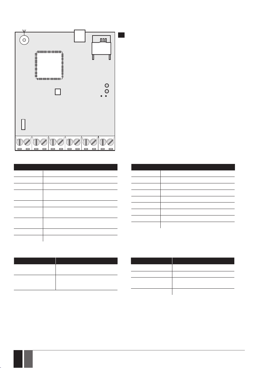
2.2. Main Unit, LED Indicator and Connector Functionality
USB
ANT
G S M
MO DE M
MIC
SIM CARD
SIM STAT
NETW
DEF
F1
Z1Z2Z3Z4Z5COMRELAY2RELAY1AC/DC
Main Unit Functionality
ANT GSM/GPRS antenna SMA type connector
USB Mini USB port
SIM CARD SIM card slot / holder
GSM MODEM GSM network 850/900/1800/1900 MHz
MIC Microphone connector
SIM STAT Red light-emitting diode indicating SIM
NETW Green light-emitting diode indicating GSM
DEF Pins for restoring default settings
F1 0.5A fuse
modem
card status
signal strength
1
Connector Functionality
AC/DC Power supply terminals
RELAY1 ESIM252 output C1 terminal
RELAY2 ESIM252 output C2 terminal
COM Common terminal
Z5 “Low” level (negative) input terminal
Z4 “Low” level (negative) input terminal
Z3 “Low” level (negative) input terminal
Z2 “High” level (positive) input terminal
Z1 “Low” level (negative) input terminal
LED Indicator Functionality
SIM STAT indication SIM card status
OFF No mains power / Successfully
Steady ON SIM card is attempting to connect
6
6 EN
connected to GSM network
to the GSM network / SIM card is
not present / PIN code enabled
NETW indication GSM signal strength
OFF No GSM signal
Flashing every 1 sec. Poor
Flashing 3 times per
sec.
Steady ON Good
Medium
ESIM252 User Manual v2.1
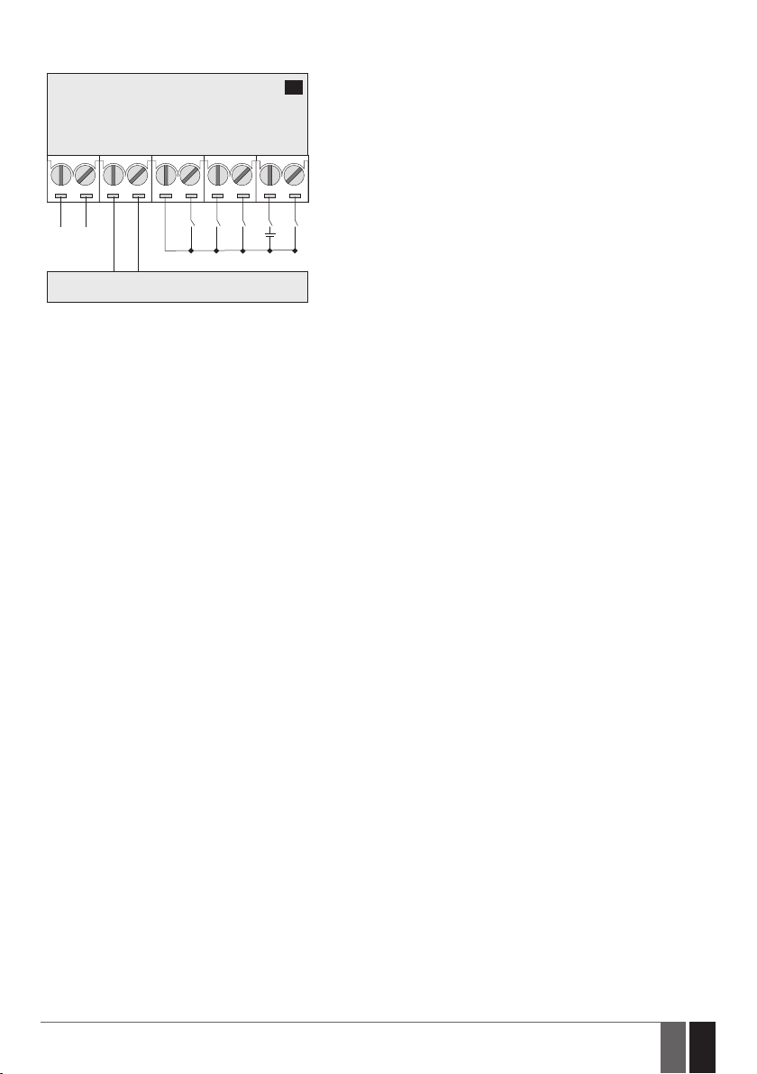
2.3. Wiring Diagram
ESIM252
AC/DC
POWER
SUPPLY
ELECTRICAL APPLIANCE
2
Z1Z2
Z3Z4Z5COMRELAY
+
-
ESIM252 User Manual v2.1
7
7EN
3. INSTALLATION
• The system should be installed indoors, in stationary environment ONLY.
• For the connection of input/output terminals, use 0.50 mm2 (0.02in2) thread unshielded cable of up to 100m (328.08ft) length.
1. Wire up the system in accordance with the wiring diagrams (see 2.3 Wiring Diagrams for more details).
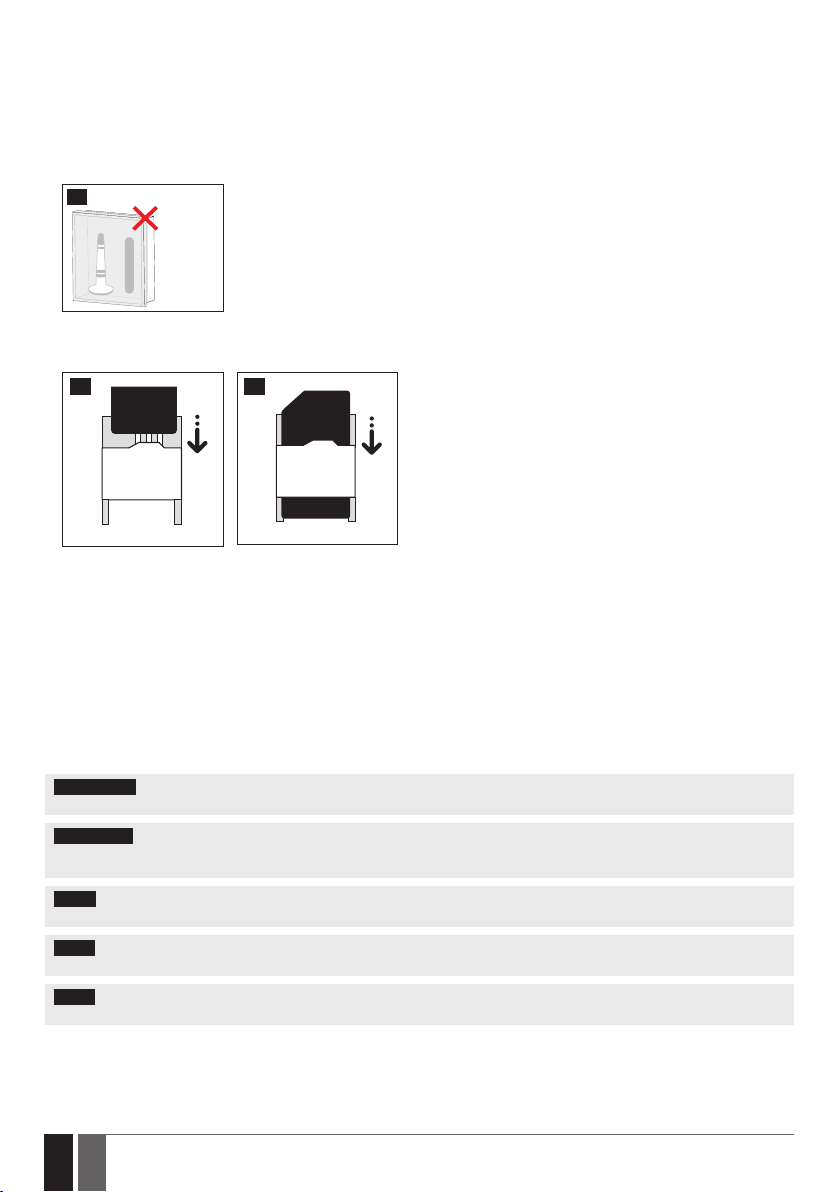
2. Connect the GSM/GPRS antenna. Based on the type of the GSM/GPRS antenna supplied with ESIM252 unit, follow the recommendations
for the antenna installation:
3
GSM/GPRS
antena
3. Disable the PIN code request of the SIM card by inserting it into a mobile phone and following the proper menu steps.
4. Once the PIN code is disabled, insert the SIM card into the SIM card slot / holder of ESIM252 system.
4
5. Ower up the system and wait until indicator SIM STAT lights up indicating SIM card status.
6. Once the indicator SIM STAT lights OFF, the illuminated indicator NETW lights up indicating that the system has successfully connected
to the GSM network. To nd the strongest GSM signal, position the GSM/GPRS antenna and follow the indications provided by NETW
indicator (see 2.2. Main Unit, LED Indicator & Connector Functionality for more details).
7. Change the system language if necessary (see 6. SYSTEM LANGUAGE for more details).
8. Change the default SMS password (see 7. SMS PASSWORD for more details).
9. Set the phone number for User 1 (see 8. USER PHONE NUMBERS for more details).
10. Set system date and time (see 9. DATE AND TIME for more details).
11. Once the system is fully congured, it is ready for use. However, if you fail to receive a reply by SMS text message from the system,
please check the SMSC (Short Message Service Center) phone number. For more details regarding the SMS center phone number, please
refer to 15.1. SMSC (Short Message Service Center) Phone Number.
Never install in the following
locations:
• inside the metal cabinet
• closer than 20cm (7.87in)
from the metal surface
and/or power lines
5
ATTENTION: The system is NOT compatible with pure 3G SIM cards. Only 2G/GSM SIM cards and 3G SIM cards with 2G/GSM prole
enabled are supported. For more details, please contact your GSM operator.
ATTENTION: We also recommend you to disable call forwarding, voice mail/text message reports on missed/busy calls (“call
catcher”) and similar services that might cause incorrect system operation. Please contact your GSM operator for more details on these
services and how to disable them.
NOTE: For maximum system reliability we recommend you do NOT use a Pay As You Go SIM card. Otherwise, in the event of insucient
credit balance on the SIM card, the system would fail to make a phone call or send SMS text messages.
NOTE: We advise you to choose the same GSM SIM provider for your system as for your mobile phone. This will ensure the fastest, most
reliable SMS text message delivery service and phone call connection.
NOTE: The system is NOT compatible with pure 3G SIM cards. Only 2G/GSM SIM cards and 3G SIM cards with 2G/GSM prole enabled are
supported. For more details, please contact your GSM operator.
8
8 EN
ESIM252 User Manual v2.1
4. GENERAL OPERATIONAL DESCRIPTION
GSM control system ESIM252 uses the GSM network for event transmission by SMS text message. When one of the 5 available listed numbers dials the system, it answers the call and the user can listen to a pre-recorded audio message and hear what is going on in the premises
once the audio message is over. The remote listening function operates only when a microphone is connected. When the “conversation” is
over, the user The system will ignore SMS requests and phone calls coming from non-listed phone numbers.
The system has 5 digital inputs (normally closed or normally open) for alarm system’s PGM output or detection device connection, such as
magnetic door contact. By connecting the input to the non-GSM alarm system’s PGM output, the user will be able to receive an SMS text
message or phone call regarding system alarm/restore, arming/disarming and other events depending on the alarm system conguration.
In addition to being informed by SMS text message or phone call regarding alarm and restore events of the inputs, the users can control
one electrical appliance by connecting it to the relay outputs. For example, users can turn ON or OFF the heating, lighting, lift the gates,
blinds etc. The output can also be used for arming/disarming by connecting it to one of the alarm system zones congured as a key-switch.
5. CONFIGURATION METHODS
5.1. SMS Text Messages
In this user manual the underscore character ”_” represents one space character. Every underscore character must be replaced
by a single space character. There must be no spaces or other unnecessary characters at the beginning and at the end of the
SMS text message.
In order to configure and control the system by SMS text message, send the text command to the ESIM252 system phone
number from one of the listed user phone numbers. The structure of SMS text message consists of 4-digit SMS password (the
SMS
default SMS password is 0000 – four zeros), the parameter and value. For some parameters the value does not apply e. g.
STATUS. The variables are indicated in lower-case letters, while a valid parameter value range is indicated in brackets.
5.2. ELDES Conguration Tool
Software ELDES Conguration Tool is intended for ESIM252 GSM control system conguration locally via USB port or remotely via GPRS
network connection. This software simplies system conguration process by allowing to use a personal computer in the process. Before
starting to use ELDES Conguration Tool software, please read the user guide provided in the software’s HELP section.
ELDES Conguration Tool is freeware and can be downloaded from at: www.eldes.lt
NOTE: ELDES Conguration Tool software is secured with SMS password. The default SMS password is 0000 (see 7. SMS PASSWORD).
5.2.1. Remote Connection
ATTENTION: The system will NOT send any data to the monitoring station while remote conguration is in progress. However, dur-
ing the remote conguration session the data messages will be queued up and transmitted to the monitoring station after the remote
conguration session is over.
ELDES Conguration Tool software provides remote system conguration ability via Internet using one of the following methods:
• ELDES proxy server (recommended). The connection can be established on the system via GPRS network.
• Running TCP/IP server on ELDES Conguration Tool (advanced). The connection can be established on the system via GPRS network.
In order to start using the remote conguration feature, please run the step-by-step wizard and follow the steps provided in the start page
of ELDES Conguration Tool software. Please, note that it will be necessary to send an SMS text message to the system’s phone number
in order to initiate the remote connection. By following the steps you will be instructed on what text must be sent to the system’s phone
number in such case.
5.2.2. Ending the Remote Connection Session
After the system conguration is complete, use one of the following methods to end the conguration process:
• Click Disconnect or Stop button and close ELDES Conguration Tool software;
• The session will automatically expire in 20 minutes. Before the last 5 minutes, the software will oer the user to extend the session for
another 20 minutes.
• Alternatively, the connection with the server can be terminated at any time by sending an SMS text message.
Terminate the
connection
SMS text message content:
ssss_ENDCONFIG
Value: ssss – 4-digit SMS password.
Example: 1111_ENDCONFIG
Once the session is expired or terminated, the system will reply with an SMS text message conrming the end of the session.
9
ESIM252 User Manual v2.1
9EN
6. SYSTEM LANGUAGE
The system comes equipped with a multiple languages for communication with the user by SMS text messages. The default system language depends on the rmware, which is based on the customer’s location.
List of currently available system languages:
• English
• Lithuanian
• Slovak
SMS text message content:
LN
Set system language
SMS
Value: LN – language index; range – [EN – English,, LT – Lithuanian, SK – Slovak].
Example: LT
Cong
NOTE: To change the language once the system has already been congured, you need to reset the device to the default conguration.
For more details on how to do this, please refer to 21.2. Restoring Default Parameters.
This operation may be carried out from the PC using the ELDES Conguration Tool software.
Tool
7. SMS PASSWORD
For security reasons, the system uses the following type of password:
SMS password – 4-digit password used for system conguration and control from user phone number by SMS text messages and logging
in to ELDES Conguration Tool software. By default, SMS password is 0000, which MUST be changed!
SMS text message content:
wwww_PSW_ssss
Set SMS password
NOTE: The system rejects the SMS text messages containing wrong SMS password even from a listed user phone number.
SMS
Cong
Tool
Value: wwww – 4-digit default SMS password; ssss – 4-digit new SMS password; range –
[0001... 9999].
Example: 0000_PSW_1111
This operation may be carried out from the PC using the ELDES Conguration Tool software.
10
10 EN
ESIM252 User Manual v2.1
8. USER PHONE NUMBERS
The system supports up to 5 user phone numbers identied as User 1 through 5. When the phone number is set, the user will be able to
congure and control the system by SMS text messages as well as by free of charge phone call and receive the input alarm/restore SMS text
messages and/or phone calls from the system (see 11. ALARM/RESTORE NOTIFICATIONS).
By default, the system ignores any incoming calls and SMS text messages from a non-listed phone number as well as it rejects the SMS text
messages containing wrong SMS password even from a listed user phone number. For more details on how to enable output control from a
non-listed phone number, please refer to 8.1. System Control from any Phone Number.
To set User 1 phone number is mandatory, while the other 4 are optional. The supported phone number format is the following:
• International (w/o plus) – The phone numbers must be entered starting with an international country code in the following format:
[international code][area code][local number], example for UK: 441709xxxxxxx.
SMS text message content:
Set user phone
number
ssss_NRu:ttteeellnnuumm
SMS
Value: ssss – 4-digit SMS password; u – user phone number slot, range – [1... 5]; ttteeellnnu-
umm – up to 15 digits administrator phone number.
Example: 1111_NR1:441709xxxxxxx
Cong
View user phone
number
Cong
Delete user phone
number
Cong
ATTENTION: The system rejects the SMS text messages containing wrong SMS password even from a listed user phone number.
ATTENTION: Once User 1 phone number is set, the system will restrict only to modify it
ATTENTION: Multiple user phone numbers can be set by a single SMS text message, Example: 1111_NR1:441709xxxxxx1_
NR5:441709xxxxxx2_NR2:441709xxxxxx3_NR3: 441709xxxxxx4
NOTE: Multiple user phone numbers can be deleted by a single SMS text message, Example: 1111_NR2:DEL_NR4:DEL_ NR3:DEL
This operation may be carried out from the PC using the ELDES Conguration Tool software.
Tool
SMS text message content:
ssss_HELPNR
SMS
Value: ssss – 4-digit SMS password.
Example: 1111_HELPNR
This operation may be carried out from the PC using the ELDES Conguration Tool software.
Tool
SMS text message content:
ssss_NRu:DEL
SMS
Value: ssss – 4-digit SMS password; u – user phone number slot, range – [1... 5].
Example: 1111_NR2:DEL
This operation may be carried out from the PC using the ELDES Conguration Tool software.
Tool
ESIM252 User Manual v2.1
11
11EN
8.1. System Control from any Phone Number
By default, the system ignores any incoming calls and SMS text messages from a non-listed phone number as well as it rejects the SMS text
messages containing wrong SMS password even from a listed user phone number. To permit/deny incoming phone calls and SMS text messages that contain a valid SMS password from any phone number, please refer to the following conguration methods.
Enable system control
from any phone
number
SMS text message content:
ssss_STR:ON
SMS
Value: ssss – 4-digit SMS password.
Example: 1111_STR:ON
Disable system
control from any
phone number
Cong
Tool
SMS
Cong
Tool
This operation may be carried out from the PC using the ELDES Conguration Tool software.
SMS text message content:
ssss_STR:OFF
Value: ssss – 4-digit SMS password.
Example: 1111_STR:OFF
This operation may be carried out from the PC using the ELDES Conguration Tool software.
12
12 EN
ESIM252 User Manual v2.1
9. DATE AND TIME
The system comes equipped with internal real-time clock (RTC) that keeps track of the current date and time. Once the system is up and
running, the user must set the correct date and time, otherwise the system will not operate properly. By default, after shutting down and
starting up the system, the date and time must be set again.
SMS text message content:
ssss_yyyy.mt.dd_hr:mn
Set date and time
SMS
Value: ssss – 4-digit SMS password; yyyy – year; mt – month, range – [01... 12]; dd – day, range
– [01... 31]; hr – hours, range – [00... 23]; mn – minutes, range – [00... 59].
Example: 1111_2014.03.16_14:33
Cong
NOTE: When the system is connected to the monitoring station via GPRS network connection (see 19. MONITORING STATION), the
date and time will be automatically synchronized with the monitoring station or Smart Security server upon the system startup.
This operation may be carried out from the PC using the ELDES Conguration Tool software.
Tool
10. INPUTS
The system comes equipped with 5 inputs identied as Z1 through Z5. Normally, the inputs are used for PGM output connection of nonGSM alarm system, motion detectors, door contacts and other passive or active digital level sensors. Once a detection device is triggered,
the system will send a notication to the user phone number. For more details, please refer to 11. ALARM/RESTORE NOTIFICATIONS.
Each input’s sensitivity level can be customized by a delay time (by default – 600 milliseconds). If an input is left triggered until the delay
time expires, the input is considered violated.
SMS text message content:
ssss_SMSEXTRA:Zn:DVin-delay
Set input delay
By default, all system inputs are set as NO (normally-open). To change the input connection type to NC (normally closed)/NO (normally
open), please refer to the following conguration methods.
Set input as NC
(normally closed)
SMS
Cong
Tool
SMS
Cong
Tool
Value: ssss – 4-digit SMS password; n – input number, range – [1... 5]; in-delay – input delay,
range – [100... 10000] milliseconds.
Example: 1111_SMSEXTRA:Z3:DV800
This operation may be carried out from the PC using the ELDES Conguration Tool software.
SMS text message content:
ssss_SMSEXTRA:Zn:LI1
Value: ssss – 4-digit SMS password; n – input number, range – [1... 5].
Example: 1111_SMSEXTRA:Z4:LI1
This operation may be carried out from the PC using the ELDES Conguration Tool software.
SMS text message content:
Set input as NO
(normally open)
Cong
The system allows to view the current input state by the following conguration method.
ESIM252 User Manual v2.1
ssss_SMSEXTRA:Zn:LI0
SMS
Value: ssss – 4-digit SMS password; n – input number, range – [1... 5].
Example: 1111_SMSEXTRA:Z2:LI0
This operation may be carried out from the PC using the ELDES Conguration Tool software.
Tool
13
13EN
View input state
SMS text message content:
ssss_INFO
SMS
Value: ssss – 4-digit SMS password.
Example: 1111_INFO
Cong
10.1. Pulse Counter
The system comes equipped with input pulse counter feature. The feature determines the number of input violation events, known as
pulses, that result in input alarm SMS text message delivery and/or phone call to the listed user phone number once the number of the set
up pulses is achieved. The time-frame between the pulses is unlimited.
By default, the pulse counter feature is disabled and the number of pulses is not set. To enable/disable it and set the number of pulses,
please refer to the following conguration methods:
Enable pulse counter
Cong
Set number of pulses
Cong
Disable pulse counter
This operation may be carried out from the PC using the ELDES Conguration Tool software.
Tool
SMS text message content:
ssss_SMSEXTRA:Zn:IE1
SMS
Value: ssss – 4-digit SMS password; n – input number, range – [1... 5].
Example: 1111_SMSEXTRA:Z2:IE1
This operation may be carried out from the PC using the ELDES Conguration Tool software.
Tool
SMS text message content:
ssss_SMSEXTRA:Zn:ICnum-pulse
SMS
Value: ssss – 4-digit SMS password; n – input number, range – [1... 5]; num-pulse – number of
pulses, range - [0... 4294967295].
Example: 1111_SMSEXTRA:Z5:IC562
This operation may be carried out from the PC using the ELDES Conguration Tool software.
Tool
SMS text message content:
ssss_SMSEXTRA:Zn:IE0
SMS
Value: ssss – 4-digit SMS password; n – input number, range – [1... 5].
Example: 1111_SMSEXTRA:Z1:IE0
Cong
NOTE: Once the pulse counter feature is in use, the input restore notications regarding a certrain input will no longer be delivered to
the listed user phone number, even if enabled.
10.2. Disabling and Enabling Inputs
By default, all inputs are enabled. Once disabled, input alarm/resetore event will no longer be followed by an SMS text message and/or
phone call. To disable/enable an individual input, please refer to the following conguration methods.
Disable input
Cong
14
14 EN
This operation may be carried out from the PC using the ELDES Conguration Tool software.
Tool
SMS text message content:
ssss_Zn:OFF
SMS
Value: ssss – 4-digit SMS password; n – input number, range – [1... 5].
Example: 1111_Z1:OFF
This operation may be carried out from the PC using the ELDES Conguration Tool software.
Tool
ESIM252 User Manual v2.1
Enable input
SMS text message content:
ssss_Zn:ON
SMS
Value: ssss – 4-digit SMS password; n – input number, range – [1... 5].
Example: 1111_Z5:ON
Cong
View input status
Cong
NOTE: Multiple inputs can be managed by a single SMS text message, Example: 1111_Z1:OFF ;Z3:ON;Z5:OFF;
This operation may be carried out from the PC using the ELDES Conguration Tool software.
Tool
SMS text message content:
ssss_STATUS
SMS
Value: ssss – 4-digit SMS password.
Example: 1111_STATUS
This operation may be carried out from the PC using the ELDES Conguration Tool software.
Tool
ESIM252 User Manual v2.1
15
15EN
11. ALARM/RESTORE NOTIFICATIONS
In the event of input alarm or restore, the system can notify the listed user phone number by the following methods that can be used
individually or simultaneously:
• SMS text message.
• Phone call.
By default, in the event of input alarm, the system will follow this pattern:
SMS
a) The system attempts to send an SMS text message containing input alarm text to the rst listed user phone number only.
b) If the user phone number is unavailable and the system fails to receive the SMS delivery report within 45 seconds, it will
attempt to send the SMS text message to the next listed user phone number. The system may fail to deliver the SMS text
message to the listed user phone number due to the following reasons:
• user’s mobile phone has been switched o.
• user’s mobile phone has been out of GSM signal coverage.
c) The system will continue sending the SMS text message to the next listed user phone numbers in the priority order until
one is available (to change this algorithm, please refer to 11.1. Enabling and Disabling Alarm/Restore Notication
Delivery to All Listed Users).
d) The system sends the SMS text message only once and will not return to the rst user phone number if the last one was
unavailable, therefore if the system ends up with all unsuccessful attempts, it will delete the queued up event from the
memory and it will no longer attempt to send it by SMS text message.
By default, input restore notication by SMS text message is disabled. Once enabled, the system will follow the SMS text message delivery pattern identically as for input alarm event.
To manage input alarm and restore SMS text messages, please refer to the following conguration methods
SMS text message content:
Disable input alarm
notication by SMS
ssss_SMSEXTRA:Zn:SCu
SMS
Value: ssss – 4-digit SMS password; n – input number, range – [1... 5]; u – user phone number
slot, range – [1... 5].
Example: 1111_SMSEXTRA:Z4:SC4
Enable input alarm
notication by SMS
Set input alarm text
16
16 EN
Cong
Tool
SMS
Cong
Tool
SMS
Cong
Tool
This operation may be carried out from the PC using the ELDES Conguration Tool software.
SMS text message content:
ssss_SMSEXTRA:Zn:SSu
Value: ssss – 4-digit SMS password; n – input number, range – [1... 5]; u – user phone number
slot, range – [1... 5].
Example: 1111_SMSEXTRA:Z3:SS1
This operation may be carried out from the PC using the ELDES Conguration Tool software.
SMS text message content:
ssss_Zn:in-alarm-text
Value: ssss – 4-digit SMS password; n – input number, range – [1... 5]; in-alarm-text – up to 24
characters input alarm text.
Example: 1111_Z2:Alarm Input2
This operation may be carried out from the PC using the ELDES Conguration Tool software.
ESIM252 User Manual v2.1
 Loading...