

Eldes ESIM110, ESIM120 User Manual
ESIM110
ESIM120
GSM SWITCHGATE CONTROLLER
User Manual v3.2
Valid for ESIM110/ESIM120 v11.03.03 and up
SAFETY INSTRUCTIONS
Please read and follow these safety guidelines to safeguard yourself and others:
• GS
M switch-gate controller ESIM110/ESIM120 (later referred to as “the system” or “ the device”) contains a built-in radio transceiver
operating in GSM 850/900/1800/1900 MHz bands.
• DO NOT use the system where it can cause potential danger and interfere with other devices – such as medical devices.
• DO NOT use the system in hazardous environment.
• DO NOT expose the system to high humidity, chemical environment or mechanical impact.
• DO NOT attempt to repair the system yourself – any repairs must be carried out by fully qualied personnel only
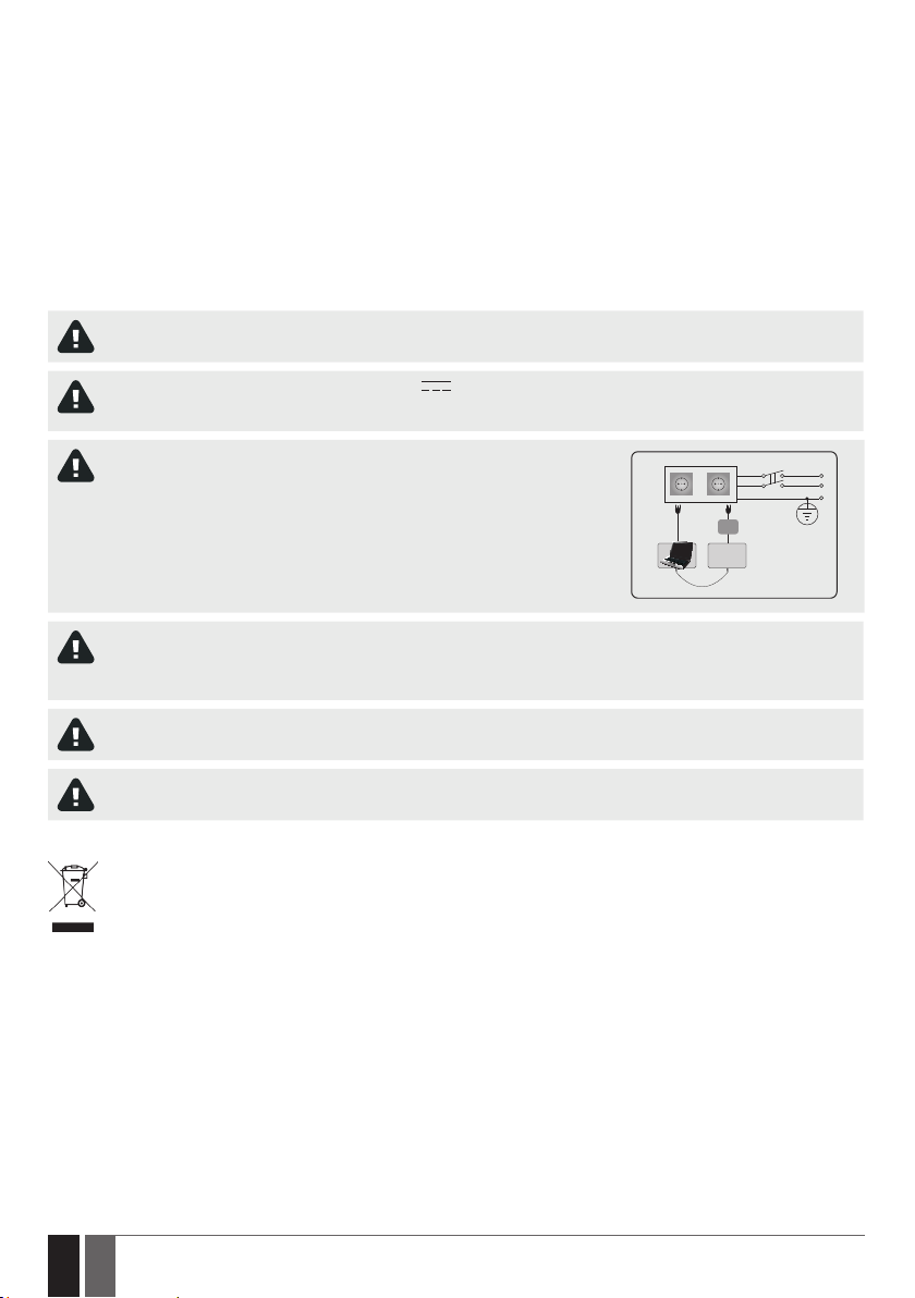
Disconnect the mains power before installing. Never install or carry out maintenance during stormy weather. The electric socket that powers the system must be easily accessible.
Please use the 10-24V 50Hz ~200mA AC or 10-24V 200mA DC power supply unit that meets the EN 60950-1 standard.
Any additional device you connect to the system, such as a computer, must also be powered by an EN 60950-1 approved
supply. When connecting the power supply to the system, switching the polarity terminal places does not have any aect.
.
External power supply can be connected to AC mains only inside installation room
with automatic 2-pole circuit breaker capable of disconnecting circuit in the event
of short circuit or over-current condition. Open circuit breaker must have a gap
between connections of more than 3mm and the disconnection current 5A.
AC/DC
ESIM110/
ESIM120
USB cable
To switch the system o, unplug the external electric power supply from or any other linked device that the system is
powered from
A blown fuse cannot be replaced by the user. The replacement fuse has to be of the kind indicated by the manufacturer (fuse
F1 model – MINISMDC050F 0.5A).
AC 230V
50 Hz/DC 24V
Phase
Null
PE
If you use a computer for the device conguration, it must be earthed.
The WEEE (Waste Electrical and Electronic Equipment) symbol on this product (see left) means it must not be disposed of in
household waste. To prevent possible harm to human health and/or the environment, you must dispose of this product in an
approved and environmentally safe recycling facility. For further information contact your system supplier, or your local waste
authority.
2
2 EN
ESIM110/ESIM120 Manual v.3.2

CONTENTS
1. GENERAL INFORMATION ...........................................................................................................................................................6
2. TECHNICAL SPECIFICATIONS ....................................................................................................................................................6
2.1. Electrical & Mechanical Characteristics .........................................................................................................................................................6
2.2. Main Unit, LED Indicator & Connector Functionality ................................................................................................................................... 7
2.3. Wiring Diagrams ................................................................................................................................................................................................8
3. INSTALLATION ...........................................................................................................................................................................9
4. GENERAL OPERATION .............................................................................................................................................................10
5. CONFIGURATION METHODS ....................................................................................................................................................10
5.1. SMS Text Messages .........................................................................................................................................................................................10
5.2. ELDES Conguration Tool ..............................................................................................................................................................................10
5.3. Remote Conguration via Web Browser ......................................................................................................................................................10
6. SYSTEM LANGUAGE .................................................................................................................................................................14
7. SMS PASSWORD .......................................................................................................................................................................15
8. ADMINISTRATOR PHONE NUMBERS .......................................................................................................................................15
9. DATE AND TIME........................................................................................................................................................................17
9.1. Automatic Date and Time Synchronization ................................................................................................................................................17
10.USER PHONE NUMBER DATABASE .........................................................................................................................................19
10.1. User Validity and Access Restriction ...........................................................................................................................................................21
11.OUTPUT (-S) ............................................................................................................................................................................ 24
11.1. Output Name (-s) ............................................................................................................................................................................................ 24
11.2. Output Control by Free of Charge Phone Call .............................................................................................................................................25
11.3. Output Control by SMS Text Message ......................................................................................................................................................... 26
11.4. Output Control Conrmation by Call Back .................................................................................................................................................. 29
11.5. Output Control from any Phone Number....................................................................................................................................................30
11.6. Automatic Output Control ............................................................................................................................................................................. 30
12.SCHEDULERS ...........................................................................................................................................................................32
13.EVENT LOG .............................................................................................................................................................................. 34
14.INPUTS.................................................................................................................................................................................... 36
14.1. Input Names and Alarm Notications ......................................................................................................................................................... 36
14.2. Disabling and Enabling Inputs ...................................................................................................................................................................... 38
15.SYSTEM INFORMATION. INFO SMS ........................................................................................................................................ 39
15.1. Periodic Info SMS ............................................................................................................................................................................................ 39
16.SYSTEM NOTIFICATIONS ........................................................................................................................................................ 40
16.1. SMSC (Short Message Service Center) Phone Number ............................................................................................................................ 40
17.GPRS NETWORK SETTINGS .....................................................................................................................................................41
18.REMOTE SYSTEM RESTART .................................................................................................................................................... 42
19.TECHNICAL SUPPORT ............................................................................................................................................................ 43
19.1. Troubleshooting ............................................................................................................................................................................................. 43
19.2. Restoring Default Parameters ..................................................................................................................................................................... 43
19.3. Updating the Firmware via USB Cable ........................................................................................................................................................ 43
20. RELATED PRODUCTS .............................................................................................................................................................44
ESIM110/ESIM120 Manual v.3.2
3
3EN

4
4 EN
ESIM110/ESIM120 Manual v.3.2

Limited Liability
The buyer agrees that the system will reduce the risk of re, theft, burglary or other danger but that it does not guarantee against the occurrence of such events. “ELDES UAB” will not take any responsibility for the loss of personal eects, property or revenue whilst using the
system. The liability of “ELDES UAB” is limited to the value of the system purchased. “ELDES UAB” is not aliated with any mobile/wireless/
cellular provider and is therefore not responsible for the quality of such services.
Manufacturer Warranty
The system carries a 24-month manufacturer warranty from “ELDES UAB”. The warranty begins the day the system is purchased by the
user and the receipt must be retained as proof of purchase date. The warranty remains valid only if the system is used as intended, following all guidelines outlined in this manual and in accordance with the operating conditions specied. The warranty is void if the system
has been exposed to mechanical impact, chemicals, high humidity, uids, corrosive and hazardous environments or force majeure factors.
Dear Customer,
Thank you for choosing to purchase the GSM switch-gate controller ESIM110/ESIM120. Your thoughtful decision will ensure reliable
solution for many years as all ELDES products are manufactured to meet the highest standards.
We are condent that you will be completely satised with your product. However, in the unlikely event that you do experience a
problem, please contact the dealer from whom you made your purchase.
UAB ELDES
www.eldes.lt
Contents of Pack
Item Quantity
1. ESIM110/ESIM120 .................................1
2. User manual ............................................1
3. GSM antenna. .........................................1
Copyright © “ELDES UAB”, 2013. All rights reserved
It is strictly forbidden to copy and distribute information in this document or pass to a third party without an advanced
written authorization from “ELDES UAB”. “ELDES UAB” reserves the right to update or modify this document and/or related products without a warning. Hereby, “ELDES UAB” declares that the GSM switch-gate controller ESIM110/ESIM120 is
in compliance with the essential requirements and other relevant provisions of Directive 1999/5/EC. The declaration of
conformity may be consulted at www.eldes.lt.
ESIM110/ESIM120 Manual v.3.2
5
5EN
1. GENERAL INFORMATION
ESIM110/ESIM120 is a micro-controller based device intended to provide access control for gate automatics, road barriers or to remotely
turn ON/OFF any electrical appliance via the GSM network.
Examples of using the system:
• Access control.
• Parking lot control of residential houses or oces.
• Gate control of private houses.
• Any electrical appliance control: lighting, watering, heating etc.
• Remote reboot of the “frozen” systems, such as computer network or a server.
Main features
• Manual output control by free of charge phone call.
• Automatic output control in accordance with the scheduled time.
• Congurable output pulse duration.
• Automatic date and time synchronization.
• Up to 5 administrators for system conguration by SMS text messages, acceptance of input alarm SMS text messages, output control
by SMS text message and free of charge phone call.
• User database capacity – up to 500 (1000 – optional) users for output control by free of charge phone call.
• User phone number validity limitation in accordance with a set deadline (date/time) or number of rings to the system.
• Output control restriction for users in accordance with the specied weekdays and time.
• Event log of 1000 events containing date and time as well as administrator/user phone number and user name who controlled the
output.
• 3 inputs with customizable alarm texts for notication on gate state or in case it gets jammed.
• Periodic self-test notication by SMS text message to administrator phone number.
2. TECHNICAL SPECIFICATIONS
2.1. Electrical & Mechanical Characteristics
Supply voltage 10-24V 50Hz ~ 200mA max / 10-24V 200mA max
Current used in standby mode up to 50mA
GSM modem frequency 850/900/1800/1900 MHz
Number of outputs 1 (ESIM110); 2 (ESIM120)
Output type Relay; NO (normally-open)
Maximum commuting output values 24V 50Hz ~ 0,5A / 24V
Number of “low” level (negative) inputs 2
Number of “high” level (positive) inputs 1
“Low” level (negative) input value range 0... 16V
“High” level (positive) input value range 5... 50V
“Low” level (negative) and “high” level
(positive) input connection type
Dimensions 70x85x57mm
Operating temperature range -20…+55oC (-30...+55oC with limitations)
Humidity 0-90% RH @ 0... +40 °C (non-condensing)
6
6 EN
NO (normally-open)
-0.8... -0.4mA
0.17 .... 1.7mA
1A
ESIM110/ESIM120 Manual v.3.2
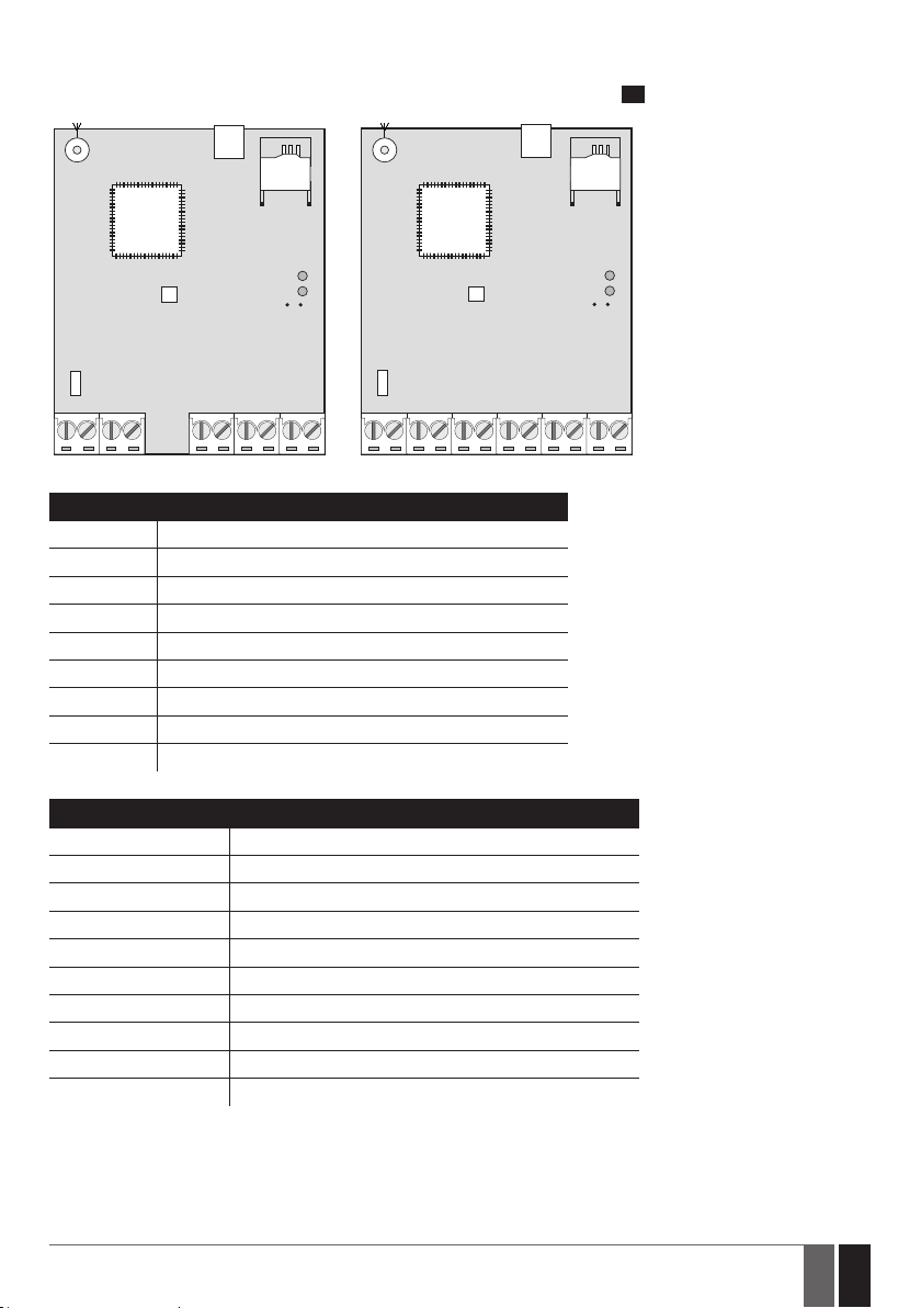
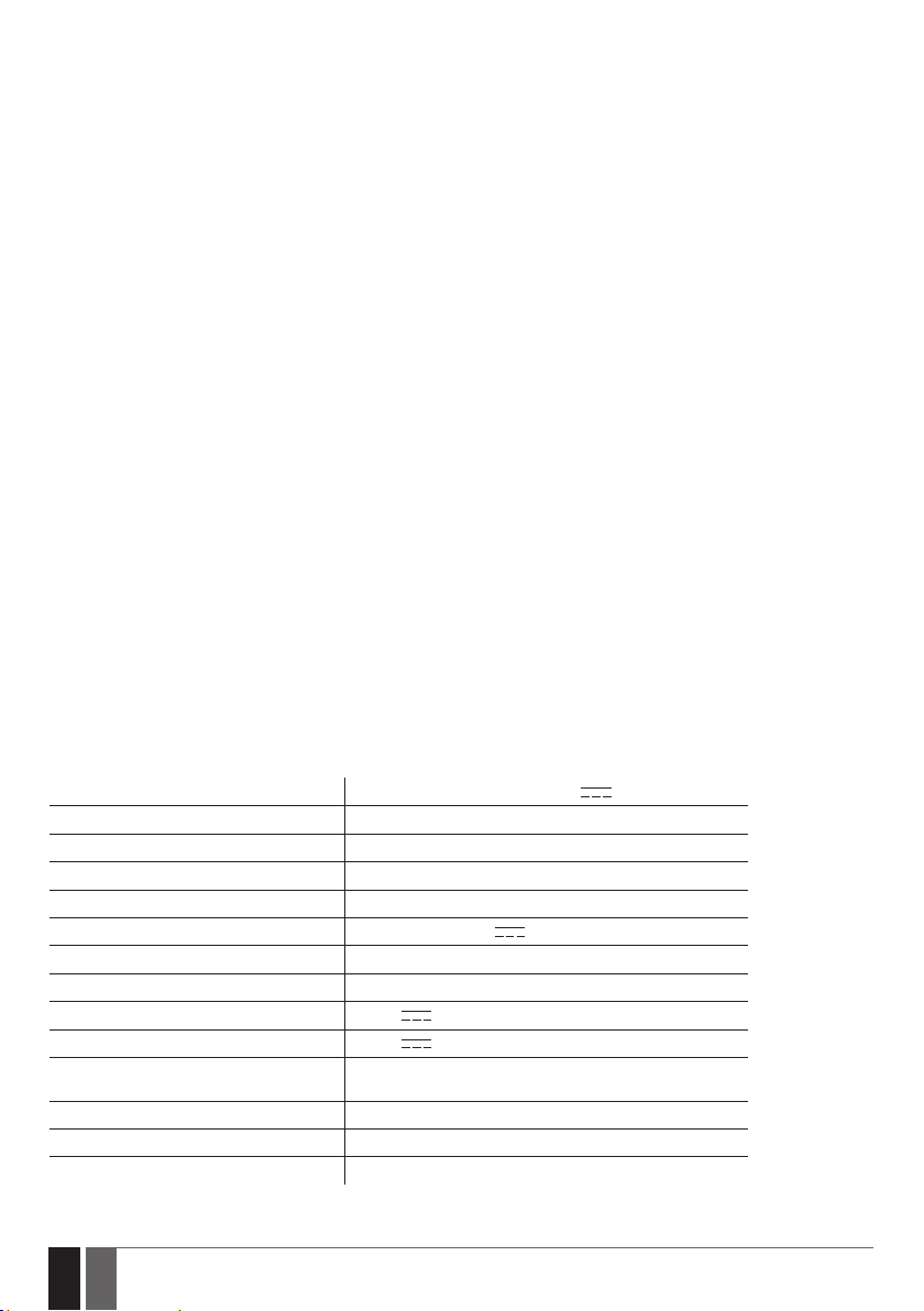
2.2. Main Unit, LED Indicator & Connector Functionality
ESIM110 ESIM120
USB
ANT
G S M
MO DE M
MIC
F1
AC/DC RELAY COM
SIM CARD
SIM STAT LED
NETW LED
DEF
Z5 Z4 Z3 Z2 Z1 AC/DC RELAY1RELAY2 COM Z5 Z4 Z3 Z2 Z1
Main Unit Functionality
ANT GSM antenna SMA type connector
USB Mini USB port
SIM CARD SIM card slot / holder
GSM MODEM GSM network 850/900/1800/1900 MHz modem
MIC N/A
SIM STAT Red light-emitting diode indicating SIM card status
NETW Green light-emitting diode indicating GSM signal strength
DEF Pins for restoring default settings
F1 0.5A fuse
ANT
G S M
MO DE M
MIC
F1
USB
SIM CARD
SIM STAT LED
NETW LED
1
DEF
Connector Functionality
AC/DC Power supply terminals
RELAY ESIM110 output C1 terminal
RELAY1 ESIM120 output C1 terminal
RELAY2 ESIM120 output C2 terminal
COM Common terminal
Z5 N/A
Z4 N/A
Z3 “Low” level (negative) input terminal
Z2 “High” level (positive) input terminal
Z1 “Low” level (negative) input terminal
ESIM110/ESIM120 Manual v.3.2
7
7EN
LED Indicator Functionality
SIM STAT indication SIM card status
Steady ON SIM card is not yet connected to the GSM network / SIM card is not present / PIN code enabled
OFF SIM card is operating successfully (if NETW LED is steady ON or ashing)
NETW indication GSM signal strength
OFF No GSM signal
Flashing every 1 sec. Poor
Flashing several times per sec. Medium
Steady ON Excellent
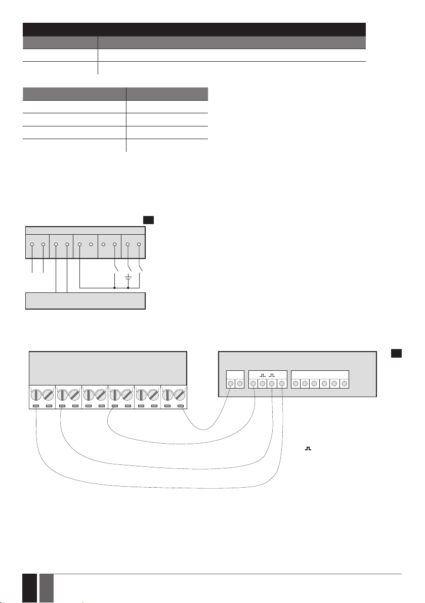
2.3. Wiring Diagrams
General wiring
ESIM 110/ESIM120
RELAY CO M Z3 Z2 Z1
AC/DC
Power
supply
GATE AUTOMATION DEVICE
2
+
-
Example of ESIM120 system wiring to gate automation device
ESIM120 GATE AUTOMATION DEVICE
AC/DC RELAY1RELAY2 COM Z5 Z4 Z3 Z2 Z1
3
+24v
GND
F0
FO= Fault output; open collector type
+24V = Power supply output for
powering aux. equipment
= Pulse input
GND = Common terminal
8
8 EN
ESIM110/ESIM120 Manual v.3.2
3. INSTALLATION
• The system should be installed indoors, in stationary environment ONLY.
• For the connection of input/output terminals, use 0.50 mm2 1 thread unshielded cable of up to 100 meters length.
1. Wire up the system in accordance with the wiring diagrams (see 2.3 Wiring Diagrams for more details).
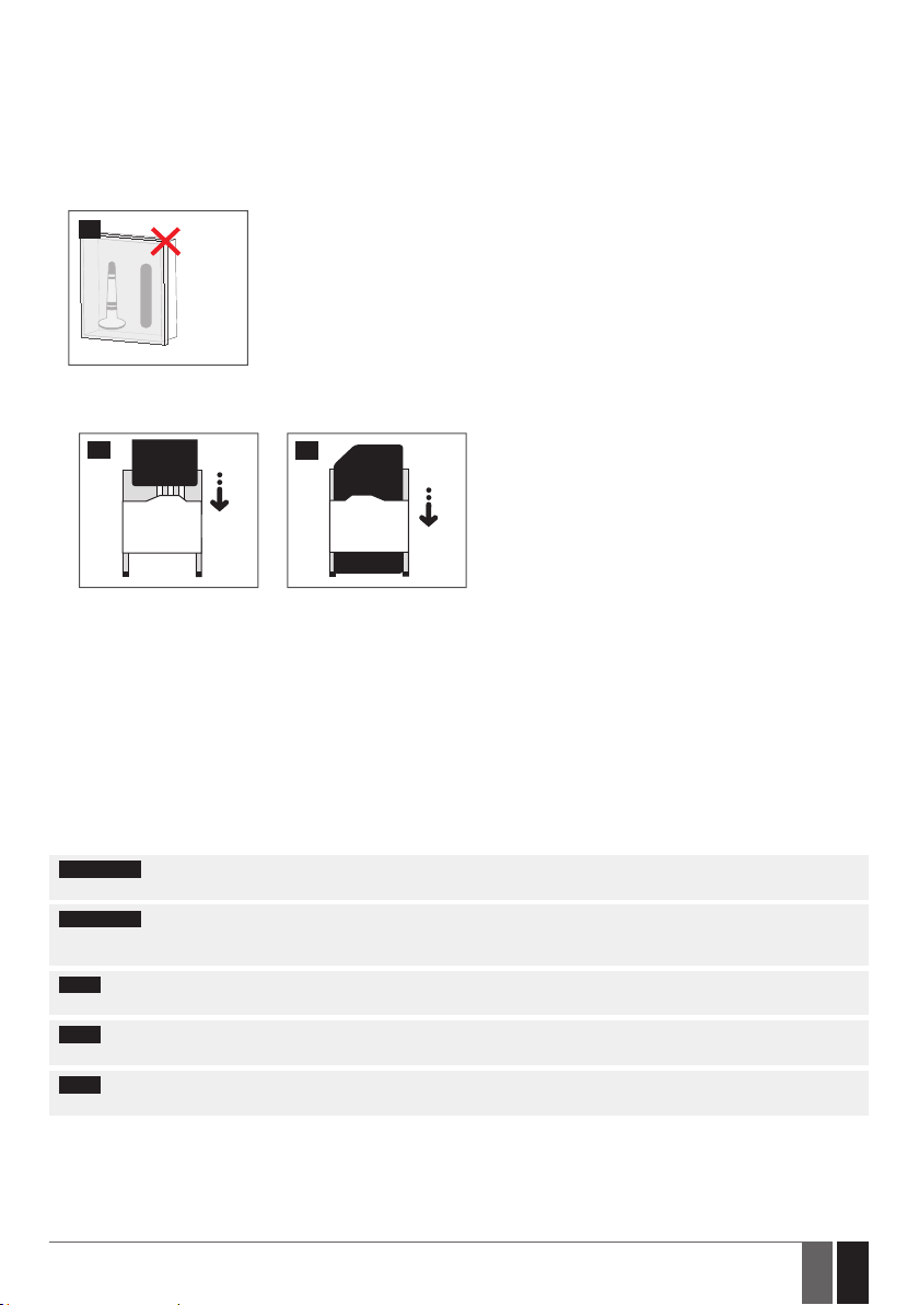
2. Connect the GSM antenna. Based on the type of the GSM antenna supplied with ESIM110/ESIM120 unit, follow the recommendations
for the antenna installation:
4
GSM
antenna
Never install in the following
locations:
• inside the metal cabinet
• closer than 20 cm from the
metal surface and/or power
lines
3. Disable the PIN code request of the SIM card by inserting it into a mobile phone and following the proper menu steps.
4. Once the PIN code is disabled, insert the SIM card into the SIM card slot / holder of ESIM110/ESIM120 system.
5
6
5. Power up the system and wait until indicator SIM STAT lights up indicating SIM card status.
6. Once the indicator SIM STAT lights OFF, the illuminated indicator NETW lights up indicating that the system has successfully connected
to the GSM network. To nd the strongest GSM signal, position the GSM antenna and follow the indications provided by NETW indicator
(see 2.2. Main Unit, LED Indicator & Connector Functionality for more details).
7. Change the system language if necessary (see 6. SYSTEM LANGUAGE for more details).
8. Change the default SMS password (see 7. SMS PASSWORD for more details).
9. Set the phone number for Admin 1 (see 8. ADMINISTRATOR PHONE NUMBERS for more details).
10. Set system date and time (see 9. DATE AND TIME for more details).
11. Once the system is fully congured, it is ready for use. However, if you fail to receive a reply by SMS text message from the system,
please check the SMSC (Short Message Service Center) phone number. For more details regarding the SMS center phone number,
please refer to 17. SMSC (Short Message Service Center) Phone Number.
ATTENTION: The system is NOT compatible with pure 3G SIM cards. Only 2G/GSM SIM cards and 3G SIM cards with 2G/GSM prole
enabled are supported. For more details, please contact your GSM operator.
ATTENTION: We also recommend you to disable call forwarding, voice mail/text message reports on missed/busy calls and
similar services that might cause incorrect system operation. Please contact your GSM operator for more details on these services and
how to disable them.
NOTE: For maximum system reliability we recommend you do NOT use a Pay As You Go SIM card. Otherwise, in the event of insucient
credit balance on the SIM card, the system would fail to make a phone call or send SMS text messages.
NOTE: We advise you to choose the same GSM SIM provider for your system as for your mobile phone. This will ensure the fastest,
most reliable SMS text message delivery service and phone call connection.
NOTE: Even though the installation process of ESIM110/ESIM120 is not too complicated, we still recommend to perform it by a person
with basic knowledge in electrical engineering and electronics to avoid any system damage.
ESIM110/ESIM120 Manual v.3.2
9
9EN
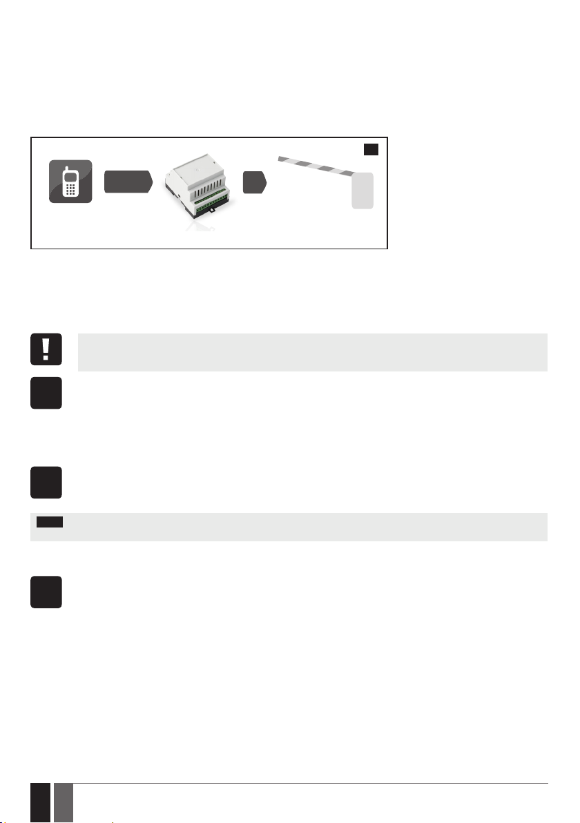
4. GENERAL OPERATION
When a phone call is made to the phone number of the SIM card inserted in ESIM110/ESIM120, the system will verify if the caller’s phone
number exists in the memory. If the caller is one of the 5 administrators or the phone number belongs to one of the 500 database users, the
system will reject the phone call, thus making the phone call free of charge, and open the gate. By ringing to ESIM110/ESIM120 again, it will
close the gate. If the phone number is not recognized, the system will reject the phone call and ignore it. The GSM switch-gate controller
can also control your gate automatically in accordance with the scheduled time or by sending an SMS text message from the administrator’s
phone number.
By connecting a sensor to one of the 3 inputs, the administrators can receive SMS text messages regarding the gates that failed to close
during the set time period.
7
CALL
User/Admin
ESIM110/ESIM120
5. CONFIGURATION METHODS
5.1. SMS Text Messages
!!! In this installation manual the underscore character ”_” represents one space character. Every underscore character
must be replaced by a single space character. There must be no spaces or other unnecessary characters at the beginning
and at the end of the SMS text message.
In order to congure and control the system by SMS text message, send the text command to the ESIM110/ESIM120 system
phone number from one of the preset administrator phone numbers. The structure of SMS text message consists of 4-digit
SMS
SMS password (the default SMS password is 0000 – four zeros), the parameter and value. For some parameters the value does
not apply e. g. STATUS. The variables are indicated in lower-case letters, while a valid parameter value range is indicated in
brackets.
5.2. ELDES Conguration Tool
Cong
5.3. Remote Conguration via Web Browser
WEB
BROWSER
10
10 EN
Software ELDES Conguration Tool is intended for ESIM110/ESIM120 GSM switch-gate controller conguration via USB port
locally. This software simplies system conguration process by allowing to use a personal computer in the process. Before
Tool
starting to use ELDES Conguration Tool software, please read the user guide provided in the software’s HELP section.
ELDES Conguration Tool is freeware and can be downloaded at: www.eldes.lt/en/download
NOTE: ELDES Conguration Tool software is secured with SMS password. The default SMS password is 0000 (see 7. SMS PASS-
WORD).
The system comes equipped with a remote conguration feature allowing to congure the parameters via any available web
browser. Before remotely connecting to ESIM110/ESIM120 via GPRS connection, ensure that:
• SIM card is inserted into the SIM CARD slot (see 2.2. Main Unit, LED & Connector Functionality).
• Mobile internet service (GPRS) is enabled on the SIM card.
• ESIM110/ESIM120 is powered up.
• Default SMS password is changed to a new 4-digit password (see 7. SMS PASSWORD).
• Admin 1 phone number is set up (see 8. ADMINISTRATOR PHONE NUMBERS).
• APN, user name and password are set up (see 17. GPRS NETWORK SETTINGS).
ESIM110/ESIM120 Manual v.3.2
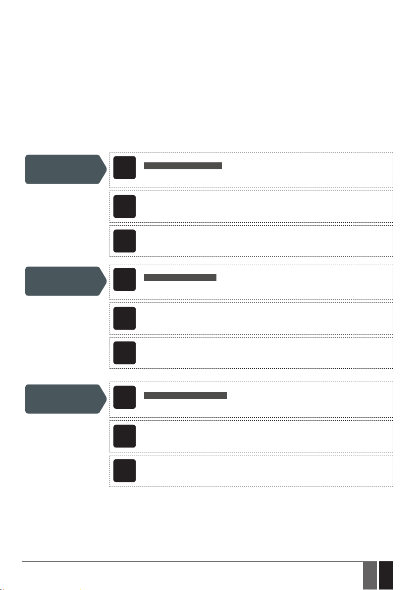
The system supports the following remote connection modes:
• CLIENT – The device connects to the conguration server making the device accessible through a web browser when the administrator
logs in via ELDES website (see 5.3.1. Establishing Remote Connection). This mode is set by default and DOES NOT require the static
IP address for the device SIM card. Default Client mode parameters are as follows:
• Server IP – cong.eldes.lt
• DNS1 – 84.32.3.34
• DNS1 – 84.32.134.1
• Port – 5555
• SERVER – The device is accessible directly through a web browser using the device IP address and local port number (see
5.3.1.Establishing Remote Connection). A static IP address, provided by GSM operator, is required for the device SIM card. This mode
is for advanced use only. Default Server mode parameters are as follows:
• Local Port – 5000
• Protocol – TCP
Set remote
connection mode
as Server
Set local port
Set protocol
SMS text message content:
ssss_SETGPRS:TYPE:SERVER
SMS
Value: ssss – 4-digit new SMS password.
Example: 1111_SETGPRS:TYPE:SERVER
Cong
This operation may be carried out from the PC using the ELDES Conguration Tool software.
Tool
WEB
This operation may be remotely carried out from the PC using the web browser.
BROWSER
SMS text message content:
ssss_SETGPRS:LPORT:lpprt
SMS
Value: ssss – 4-digit new SMS password; lpprt – local port number, range – [1... 65535].
Example: 1111_SETGPRS:LPORT:5000
Cong
This operation may be carried out from the PC using the ELDES Conguration Tool software.
Tool
WEB
This operation may be remotely carried out from the PC using the web browser.
BROWSER
SMS text message content:
sssss_SETGPRS:PROTOCOL:ptc
SMS
Value: ssss – 4-digit SMS password; ptc – protocol, range – [TCP... UDP].
Example: 1111_SETGPRS:PROTOCOL:UDP
Cong
This operation may be carried out from the PC using the ELDES Conguration Tool software.
Tool
ESIM110/ESIM120 Manual v.3.2
WEB
This operation may be remotely carried out from the PC using the web browser.
BROWSER
11
11EN
Set remote
connection mode as
Client
Set server IP address
Set server port
SMS text message content:
ssss_SETGPRS:TYPE:CLIENT
SMS
Value: ssss – 4-digit new SMS password.
Example: 1111_SETGPRS:TYPE:CLIENT
Cong
This operation may be carried out from the PC using the ELDES Conguration Tool software.
Tool
WEB
This operation may be remotely carried out from the PC using the web browser.
BROWSER
SMS text message content:
ssss_SETGPRS:IP:add.add.add.add
SMS
Value: ssss – 4-digit SMS password; add.add.add.add – server IP address.
Example: 1111_SETGPRS:IP:65.82.119.5
Cong
This operation may be carried out from the PC using the ELDES Conguration Tool software.
Tool
WEB
This operation may be remotely carried out from the PC using the web browser.
BROWSER
SMS text message content:
ssss_SETGPRS:PORT:pprrt
SMS
Value: ssss – 4-digit SMS password; pprrt – server port number, range – [1... 65535].
Example: 1111_SETGPRS:PORT:5521
Cong
This operation may be carried out from the PC using the ELDES Conguration Tool software.
Tool
Set DNS1 server IP
address
Set DNS2 server IP
address
12
12 EN
WEB
This operation may be remotely carried out from the PC using the web browser.
BROWSER
Cong
This operation may be carried out from the PC using the ELDES Conguration Tool software.
Tool
WEB
This operation may be remotely carried out from the PC using the web browser.
BROWSER
Cong
This operation may be carried out from the PC using the ELDES Conguration Tool software.
Tool
WEB
This operation may be remotely carried out from the PC using the web browser.
BROWSER
ESIM110/ESIM120 Manual v.3.2

View remote
conguration
parameters
SMS text message content:
ssss_SETGPRS?
SMS
Value: ssss – 4-digit SMS password.
Example: 1111_SETGPRS?
Cong
This operation may be carried out from the PC using the ELDES Conguration Tool software.
Tool
WEB
This operation may be remotely carried out from the PC using the web browser.
BROWSER
5.3.1. Establishing Remote Connection
1. In order to activate a remote connection, please send the following SMS text message from user phone number. Upon the successful
SMS text message delivery, the system establishes a connection session for 20 minutes. An SMS reply, containing temporal user name
and password, will be sent shortly.
SMS text message content:
Establish remote
connection
ssss_CONNECT:PROFILE1
SMS
Value: ssss – 4-digit new SMS password.
Example: 1111_CONNECT:PROFILE1
To set a dierent session duration or connect for a custom session duration, please refer to the following conguration methods.
Cong
Set session duration
This operation may be carried out from the PC using the ELDES Conguration Tool software.
Tool
WEB
This operation may be remotely carried out from the PC using the web browser.
BROWSER
Establish remote
connection for custom
session duration
Alternatively, the system supports remote connection establishment by making a phone call from the administrator phone number to
the system. Once the call is received, the system rejects the call thus making it free of charge and replies with the login details by SMS
text message to the administrator phone number. By default, this feature is disabled. To enable/disable it, please refer to the following
conguration methods.
Enable/disable
remote connection
establishment by
phone call
ESIM110/ESIM120 Manual v.3.2
SMS text message content:
ssss_CONNECT:TIMEOUT:ses-d
SMS
Value: ssss – 4-digit new SMS password; ses-d – session duration, range – [0... 14400] mi-
nutes.
Example: 1111_CONNECT:TIMEOUT:120
Cong
Tool
This operation may be carried out from the PC using the ELDES Conguration Tool software.
WEB
This operation may be remotely carried out from the PC using the web browser.
BROWSER
13
13EN
NOTE: 0 value sets unlimited session duration.
NOTE: ELDES Conguration Tool software and remote conguration web interface allows to set the unlimited session duration value.
NOTE: Once the remote connection establishment by phone call is enabled, the specied administrator will no longer be able to
control the output via free of charge phone call.
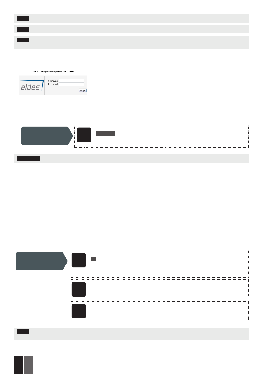
2. a) If running in Client mode, open a web browser and type in http://www.eldes.lt/login.
b) If running in Server mode, open a web browser and type in http://deviceIPaddress:localport
3. Enter the received login details and press Login button.
4. After the system conguration is complete, use one of the following methods to end the conguration process:
• Wait for the session timeout and the system to reply with an SMS text message conrming the end of the session.
• Shut down the connection with the conguration server at any time by sending an SMS text message.
Shut down the
connection with
conguration server
ATTENTION: Output control is disabled during the remote conguration process.
SMS text message content:
ssss_STOP
SMS
Value: ssss – 4-digit new SMS password.
Example: 1111_STOP
6. SYSTEM LANGUAGE
The system comes equipped with a multiple languages for communication with the administrator by SMS text messages. The default
system language depends on the rmware, which is based on the customer’s location.
List of currently available system languages:
• English
• Estonian
• German
• Lithuanian
• French
• Slovak
SMS text message content:
LN
Set system language
NOTE: To change the language once the system has already been congured, you need to reset the device to the default congura-
tion. For more details on how to do this, please refer to 19.2. Restoring Default Parameters.
14
14 EN
SMS
Value: LN – language index; range – [EN – English, EE – Estonian, DE – German, LT – Lithua-
nian, FR – French, SK – Slovak].
Example: LT
Cong
This operation may be carried out from the PC using the ELDES Conguration Tool software.
Tool
WEB
This operation may be remotely carried out from the PC using the web browser.
BROWSER
ESIM110/ESIM120 Manual v.3.2
 Loading...