

Eldes ESIM022 User Manual
ESIM022
GSM AUTO DIALLER
User Manual v1.2
SAFETY INSTRUCTIONS
Please read and follow these safety guidelines to safeguard yourself and others:
• GSM auto dialler ESIM022 (later referred to as “the system” or “the device”) contains a builtin radio transceiver operating in GSM 900/1800 MHz bands.
• DO NOT use the system where it can cause potential danger and interfere with other
devices – such as medical devices.
• DO NOT use the system in hazardous environment.
• DO NOT expose the system to high humidity, chemical environment or mechanical impact.
• DO NOT attempt to repair the system yourself – any repairs must be carried out by fully
qualied personnel only.
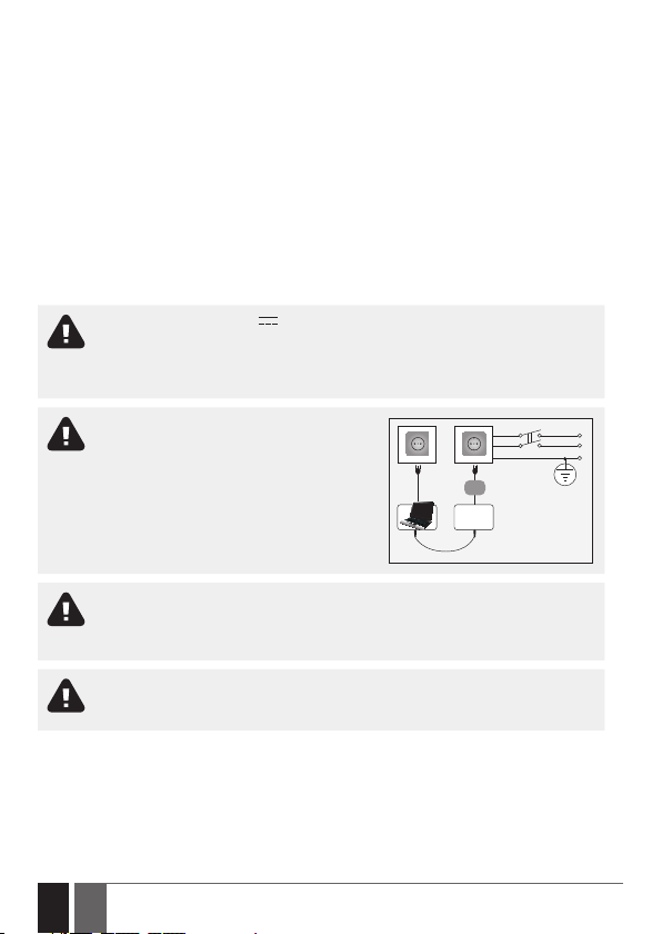
Please, use the 12-15 V 300 mA DC power supply unit that meets the EN
60950-1 standard. Any additional device you connect to the system, such as a
computer, must also be powered by an EN 60950-1 approved supply. When connecting the power supply to the system, mind the polarity terminals. DO NOT
switch the polarity terminals places.
External power supply must be reachable
and can be connected to AC mains only
inside installation room with automatic
2-pole circuit breaker capable of disconnecting circuit in the event of short circuit or
over-current condition. Open circuit breaker
must have a gap between connections of
more than 3mm (0.12in) and the disconnection current 5A.
Disconnect the mains power before installing. Never install or carry out maintenance during stormy weather. The electric socket that powers the system must be
easily accessible. In case of power cut, the system is powered by a back-up battery
(if any).
WARNING: Only use the approved 8.4V 250mAh rechargeable Ni-Mh 6HR61
(IEC)/7.2H5 (ANSI/NEDA) back-up battery with the system to avoid re or explosion. Take care when connecting positive and negative battery terminals.
2
2 EN
ESIM022
USB cable
ESIM022 User manual v1.2
DC 12-15 V
Phase
Null
PE
To switch the system o, unplug the external electric power supply, disconnect
the back-up battery or any other linked device that the system is powered from. A
blown fuse cannot be replaced by the user. The replacement fuse has to be of the
kind indicated by the manufacturer (Fuse F1 model – miniSMDC 0,5A).
If you use a computer for the device conguration, it must earthed.
The WEEE (Waste Electrical and Electronic Equipment) marking on this product (see right) or its
documentation indicates that the product must not be disposed of together with household waste. To
prevent possible harm to human health and/or the environment, the product must be disposed on in
an approved and environmentally safe recycling process. For further information on how to dispose of
this product correctly, contact the system supplier, or the local authority responsible for waste disposal
in your area.
ESIM022 User manual v1.2
3
3

Contents
1. GENERAL INFORMATION .............................................................................................. 7
2. TECHNICAL SPECIFICATIONS ........................................................................................ 8
2.2. Wiring Diagrams .......................................................................................................................... 10
3. INSTALLATION ............................................................................................................. 11
4. GENERAL OPERATION DESCRIPTION .......................................................................... 14
5. CONFIGURATION METHODS ........................................................................................ 14
5.1. SMS Text Messages .................................................................................................................... 14
5.2. ELDES Conguration Tool .......................................................................................................... 14
6. USER PHONE NUMBERS .............................................................................................. 15
7. DATE AND TIME............................................................................................................ 17
8. INPUTS ......................................................................................................................... 18
8.1. Input Z1 ........................................................................................................................................ 18
8.2. Input Z2 ........................................................................................................................................ 19
9. TAMPER .......................................................................................................................25
10. ALARM/RESTORE NOTIFICATIONS ............................................................................26
11. OUTPUT ....................................................................................................................... 32
11.1. Output Name ............................................................................................................................... 32
11.2. Turning Output ON and OFF ......................................................................................................33
12. BACK-UP BATTERY AND MAINS POWER SUPPLY STATUS MONITORING ..................34
13. SYSTEM INFORMATION. STATUS SMS ........................................................................38
13.1. Periodic Status SMS ....................................................................................................................39
14. SYSTEM NOTIFICATIONS ............................................................................................40
15. ON-BOARD TEMPERATURE SENSOR ..........................................................................44
16. REMOTE LISTENING ....................................................................................................44
17. TECHNICAL SUPPORT .................................................................................................46
17.1. Troubleshooting .........................................................................................................................46
17.2. Restoring Default Parameters ................................................................................................46
17.3. Updating the Firmware via USB Cable ..................................................................................... 47
18. RELATED PRODUCTS ..................................................................................................48
4
4 EN
ESIM022 User manual v1.2

Copyright © “ELDES UAB”, 2014. All rights reserved
It is strictly forbidden to copy and distribute information in this document or pass to
a third party without an advanced written authorization from “ELDES UAB”. “ELDES
UAB” reserves the right to update or modify this document and/or related products
without a warning. Hereby, “ELDES UAB” declares that the GSM auto dialler ESIM022
is in compliance with the essential requirements and other relevant provisions of Directive 1999/5/EC. The declaration of conformity may be consulted at www.eldes.lt.
ESIM022 User manual v1.2
5
5

Limited Liability
The buyer agrees that the system will reduce the risk of re, theft, burglary or other danger but
that it does not guarantee against the occurrence of such events.
“ELDES UAB” will not take any responsibility for the loss of personal eects, property or revenue
whilst using the system. The liability of “ELDES UAB” is limited to the value of the system
purchased.
“ELDES UAB” is not aliated with any mobile/wireless/cellular provider and is therefore not
responsible for the quality of such services.
Manufacturer Warranty
The system carries a 24-month manufacturer warranty from “ELDES UAB”.
The warranty begins the day the system is purchased by the user and the receipt must be retained as proof of purchase date. The warranty remains valid only if the system is used as intended,
following all guidelines outlined in this manual and in accordance with the operating conditions
specied.
The warranty is void if the system has been exposed to mechanical impact, chemicals, high
humidity, uids, corrosive and hazardous environments or force majeure factors.
Dear Customer,
Thank you for choosing to purchase the GSM auto dialler ESIM022. Your thoughtful decision
will ensure reliable solution for many years as all ELDES products are manufactured to meet
the highest standards.
We are condent that you will be completely satised with your product. However, in the
unlikely event that you do experience a problem, please contact the dealer from whom you
made your purchase.
UAB ELDES
www.eldes.lt
Contents of Pack
Item Quantity
1. ESIM022 ...............................................................1
2. User manual .........................................................1
Not included:
• SIM card – we recommend you get a contract SIM, not Pay As You Go.
• Back-up battery - can be obtained from your local distributor.
• miniUSB cable - can be obtained from your local distributor.
• Temperature sensor - can be obtained from your local distributor.
• Microphone - can be obtained from your local distributor
6
6 EN
ESIM022 User manual v1.2

1. GENERAL INFORMATION
ESIM022 is a micro-controller based device intended to receive alarm/restore events by SMS text
message or phone call and control an electrical appliance via the GSM network.
Examples of using the system:
• Notication of system events, such as arming/disarming, alarm/restore from non-GSM alarm
system.
• Non-GSM alarm system arming/disarming by SMS text message.
• Any electrical appliance control: lighting, watering, heating etc.
• Remote reboot of the “frozen” systems, such as computer network or a server.
• Notication of failure or restoration of an electronic device by SMS text message or phone call.
Main features:
• Conguration by SMS text message and PC.
• Up to 2 users for system conguration, control and acceptance of system event notications
by SMS text messages or phone calls.
• 2 inputs customizable as NC or NO.
• Input Z1 mode: digital.
• Input Z2 modes: digital or temperature sensor for 1 external temperature sensor connection.
• 1 open-collector output for electrical appliance control or non-GSM alarm system arming/
disarming (keyswitch).
• Tamper switch for system sabotage detection.
• Optional back-up battery to maintain the power for up to 12 hours and notify the user
regarding mains power loss and restore.
• Periodic self-test notication by SMS text message to user phone number.
• Customizable notication texts.
ESIM022 User manual v1.2
7
7
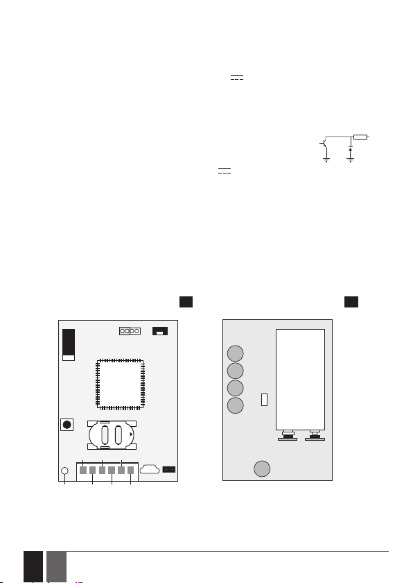
2. TECHNICAL SPECIFICATIONS
C1Z2DCCOM
COM
SIM CARD
TAMPER
RESET
MIC
LED
ANT
USB
Z1
OPEN
G S M
MO DE M
FW
+
BATTERY
-
F1
2.1. Electrical & Mechanical Characteristics
Supply voltage .....................................................12-15 V 300 mA max
Average current used in idle state ................... 16 mA
Supported back-up battery (optional) ............8.4V 250mAh rechargeable Ni-Mh 6HR61
GSM modem frequency ......................................900/1800 MHz
Number of outputs .............................................1
Output circuit .......................................................Open collector output.
Output is pulled to COM when
Maximum commuting output values ...............30 V 200 mA
Number of inputs................................................2
Supported temperature sensor model ............Maxim®/Dallas® DS18S20, DS18B20
PCB dimensions....................................................71x50x27mm (2.80x1.97x1.06in)
Enclosure dimensions.........................................96x59x34mm (3.78x2.32x1.34in)
Operating temperature range ...........................-30…+55 °C (-35...+55 °C with limitations)
(-22... +131°F (-31... +131°F))
Humidity ...............................................................0-90% RH @ 0... +40°C
(0-90% RH @ +32... +104°F) (non-condensing)
2.2. Main Unit, LED Indicator & Connector Functionality
(IEC)/7.2H5 (ANSI/NEDA)
turned ON.
1 R
OUT
8
8 EN
Front Back
1 2
ESIM022 User manual v1.2
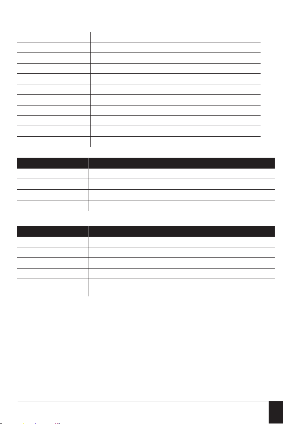
Main Unit Functionality
ANT GSM antenna
FW Pins for rmware update
TAMPER Tamper switch
GSM MODEM GSM network 900/1800 MHz modem
RESET Button for restoring default settings
SIM CARD SIM card slot / holder
LED Light-emitting diode indicating system status
USB Mini USB port
MIC Microphone connector
-/+ Backup battery slots
F1 0.5A fuse
LED indication Description
OFF No power supply
Flashing every 30 ms SIM card is not present / PIN code enabled
Flashing every 0,5 sec. Searching for GSM network
Flashing every 1 sec. Connected to GSM network/system operating successfully
Connerctors Description
Z1 Digital input terminal
COM Common terminal
Z2 Digital input terminal/temperature sensor data terminal (DATA)
DC Positive power supply terminal
C1 Open-collector output terminal/temperature sensor power
supply terminal (+4V)
ESIM022 User manual v1.2
9
9
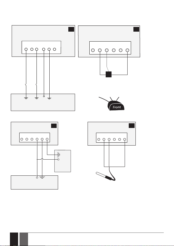
2.2. Wiring Diagrams
ESIM022
Vinson DS18B20
digital thermometer
black
yellow
red
COMZ1 Z2 DC C1COM
General wiring Temperature sensor wiring
ESIM022
3 4
ESIM022
Z1 Z2 COMCOM DC C1
COMZ1 Z2 DC C1COM
DATA
+4V
PGM1
PGM2
GND
DS18S20
temperature sensor
GND
DATA
+4V
+12V
Alarm system or other appliance
Output wiring Vinson DS18B20 digital thermometer wiring
ESIM022
COMZ1 Z2 DC C1COM
+12 V
Alarm system or other appliance
5
+
+
Electrical
appliance
5
10
10 EN
ESIM022 User manual v1.2
3. INSTALLATION
• The system should be installed indoors, in stationary environment ONLY.
• For the connection of input/output terminals, use 0.50mm2 (0.02in2) thread unshielded cable
of up to 100m (328.08ft) length.
1. Wire up the system in accordance with the wiring diagrams (see 2.3 Wiring Diagrams for
more details).
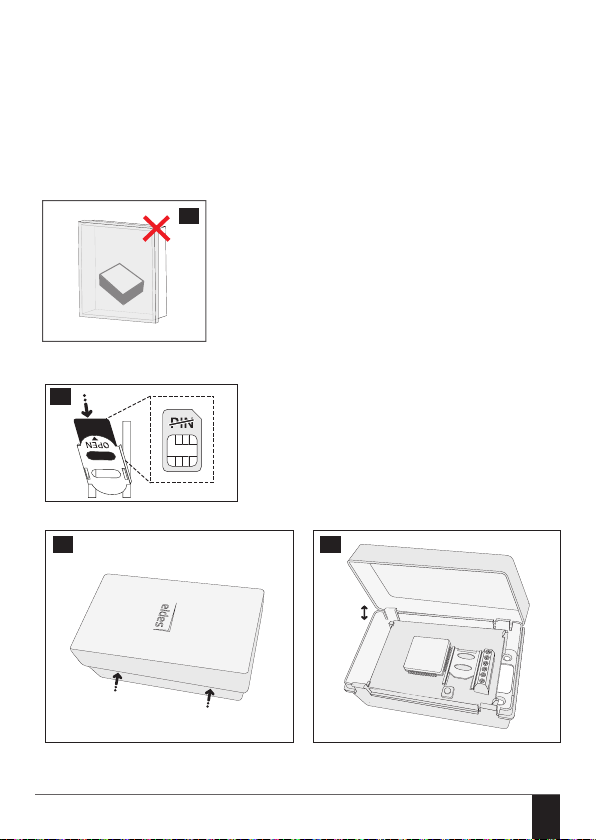
2. When placing the system, follow the recommendations:
Never install in the following locations:
6
• inside the metal cabinet
• closer than 20cm (7.87in) to the metal
surface and/or power lines
3. Disable the PIN code request of the SIM card by inserting it into a mobile phone and following
the proper menu steps.
7
4. Open the enclosure of ESIM022 system.
8 9
ESIM022 User manual v1.2
11
11
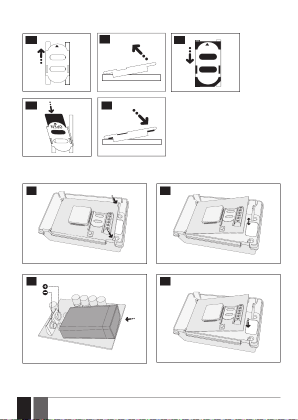
5. Once the PIN code is disabled, insert the SIM card into the SIM card slot / holder of ESIM022
OPEN
system.
10
OPEN
11
12
OPEN
13
14
6. If you have obtained a back-up battery with your system, insert it into the battery slots. Take
care when connecting positive and negative battery terminals.
15 16
17 18
12
12 EN
ESIM022 User manual v1.2
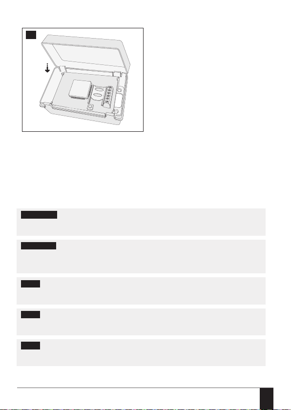
7. Close the enclosure of ESIM022.
9
8. Power up the system and wait until the LED indicator lights up indicating system status. Wait
until the LED indicator starts ashing every 1 second indicating successful connection to GSM
network and system operation (see 2.2. Main Unit, LED Indicator & Connector Functiona-
lity for more details).
9. Set the phone number for User 1.
10. Set system date and time.
11. Once the system is fully congured, it is ready for use.
ATTENTION: The system is NOT compatible with pure 3G SIM cards. Only 2G/GSM SIM cards
and 3G SIM cards with 2G/GSM prole enabled are supported. For more details, please contact your GSM operator.
ATTENTION: We also recommend you to disable call forwarding, voice mail/text mes-
sage reports on missed/busy calls and similar services that might cause incorrect sys-
tem operation. Please contact your GSM operator for more details on these services and
how to disable them.
NOTE: For maximum system reliability we recommend you do NOT use a Pay As You Go
SIM card. Otherwise, in the event of insucient credit balance on the SIM card, the system
would fail to make a phone call or send SMS text messages.
NOTE: We advise you to choose the same GSM SIM provider for your system as for your
mobile phone. This will ensure the fastest, most reliable SMS text message delivery service
and phone call connection.
NOTE: Even though the installation process of ESIM022 is not too complicated, we still
recommend to perform it by a person with basic knowledge in electrical engineering and
electronics to avoid any system damage.
ESIM022 User manual v1.2
13
13

4. GENERAL OPERATION DESCRIPTION
GSM auto dialler ESIM022 uses the GSM network for event transmission by SMS text message.
When one of the two available listed numbers dials the system, it answers the call and the user
can listen for up to 60 seconds to what is going on in the premises. This function operates only
when a microphone is connected. The system will ignore SMS requests and phone calls coming
from unknown phone numbers.
The system has 2 digital inputs (normally closed or normally open) for alarm system’s PGM output
or detection device connection, such as magnetic door contact. By connecting the input to the
non-GSM alarm system’s PGM output, you will be able to receive an SMS text message or phone call regarding system alarm/restore, arming/disarming and other events depending on alarm
system conguration. In addition to being informed by SMS text message or phone call regarding
alarm and restore events of the inputs, the users can control one electrical appliance by connecting it to the open-collector output. For example, users can turn ON or OFF the heating, lighting,
lift the gates, blinds etc. The output can also be used for arming/disarming by connecting it to one
of the alarm system zones congured as a keyswitch.
The system is protected from sabotage by built-in tamper switch resulting in user notication by
SMS text message if the enclosure is tampered.
ESIM022 can be equipped with an external temperature sensor for temperature monitoring.
The system may be equipped with a back-up battery allowing to maintain the power and notify
the user by SMS text message regarding mains power loss and restore events.
5. CONFIGURATION METHODS
!!! In this user manual the underscore character ”_” represents one space character. Every
underscore character must be replaced by a single space character. There must be no spaces
or other unnecessary characters at the beginning and at the end of the SMS text message.
5.1. SMS Text Messages
SMS
5.2. ELDES Conguration Tool
Cong
Tool
NOTE: Conguration by USB cable and ELDES Conguration Tool software does not require
the external power supply to be connected and/or back-up battery to be inserted in the device.
14
14 EN
In order to congure the system by SMS text message, send the text command to
the ESIM022 system phone number from any of the listed user phone numbers.
The structure of SMS text message consists of the parameter and value. For some
parameters the value does not apply e. g. STATUS. The variables are indicated in
lower-case letters, while a valid parameter value range is indicated in brackets.
Software ELDES Conguration Tool is intended for ESIM022 GSM auto dialler
conguration via USB port locally. This software simplies system conguration
process by allowing to use a personal computer in the process. Before starting to
use ELDES Conguration Tool software, please read the user guide provided in
the software’s HELP section.
ELDES Conguration Tool is freeware and can be downloaded at:
www.eldes.lt/en/download
ESIM022 User manual v1.2
6. USER PHONE NUMBERS
The system supports up to 2 user phone numbers identied as User 1 through 2. When the phone
number is set, the user will be able to congure the system by SMS text messages as well as to
receive the alarm phone calls and alarm/restore SMS text messages from the system (see 10.
ALARM/RESTORE NOTIFICATIONS).
The system ignores any incoming calls and SMS text messages from a non-listed phone number.
To set User 1 phone number is mandatory, while User 2 is optional. The supported phone number
formats are the following:
• International (with plus) – The phone numbers must be entered starting with plus and
an international country code in the following format: +[international code][area code][local number], example for UK: +44170911XXXX1.
• International (with 00) – The phone numbers must be entered starting with 00 and an
international country code in the following format: 00[international code][area code][local
number], example for UK: 0044170911XXXX1.
• Local – The phone numbers must be entered starting with an area code in the following
format: [area code][local number], example for UK: 0170911XXXX1.
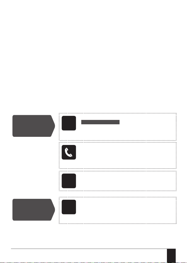
SMS text message content:
NRup:ttteeellnnuumm
Set user phone
number
SMS
Value: up – user phone number slot, range – [1... 2];
ttteeelln nuumm – up to 15 digits user phone number.
Example: NR1:+44170911XXXX1
By dialling the phone number of the system for the
rst time, the system will reject the phone call and automatically set up the phone number as User 1 phone
number that the phone call has been made from. This
feature DOES NOT apply to User 2 phone number.
View user phone
number
ESIM022 User manual v1.2
Cong
Tool
Cong
Tool
This operation may be carried out from the PC using the
ELDES Conguration Tool software.
This operation may be carried out from the PC using the
ELDES Conguration Tool software.
15
15
 Loading...