


DMX
PROGRAMMER
DMX-512
©Elation Professional®
4295 Charter Street
Los Angeles Ca. 90058
Rev. 7/04 |
www.elationlighting.com |
|
DMX Programmer™ |
Table of Contents |
|
FLOW CHART................................................................................................ |
1 |
|
CONTROLS & FUNCTIONS....................................................................... |
2 |
|
REAR CONTROLS......................................................................................... |
4 |
|
DMX-512 SET UP & ADDRESSING.............................................................. |
5 |
|
PROGRAMMING SCENES.......................................................................... |
9 |
|
PROGRAMMING SCENES REVIEW:....................................................... |
10 |
|
SCENE |
COPY:....................................................................................... |
11 |
SCENE |
EDITING:................................................................................... |
11 |
RESET MEMORY.................................................................................... |
11 |
|
DELETE SCENE .................................................................................... |
11 |
|
RECORDING PROGRAMS........................................................................... |
12 |
|
EDITING PROGRAMS................................................................................... |
13 |
|
INSERT A STEP:.................................................................................... |
13 |
|
DELETE A STEP:.................................................................................... |
14 |
|
DELETE A COMPLETE PROGRAM:...................................................... |
14 |
|
PLAYBACK SCENES & PROGRAMS........................................................... |
15 |
|
MANUAL RUN SCENES:....................................................................... |
15 |
|
MANUAL RUN PROGRAMS.................................................................. |
15 |
|
AUTO RUN PROGRAMS....................................................................... |
15 |
|
MUSIC RUN PROGRAMS..................................................................... |
15 |
|
RESET ALL MEMORY .................................................................................. |
15 |
|
ASSIGNABLE JOYSTICK.............................................................................. |
16 |
|
BLACKOUT DELAY TIME............................................................................. |
17 |
|
FADER LEVEL DISPLAY (PERCENT OR VALUE)........................................ |
17 |
|
READ AND WRITE A CF CARD.................................................................. |
18 |
|
SOFTWARE DOWNLOADING...................................................................... |
19 |
|
DATA UPLOAD/DOWNLOAD....................................................................... |
20 |
|
TROUBLE SHOOTING................................................................................. |
23 |
|
DIPSWITCH DMX ADDRESS CHARTS....................................................... |
24 |
|
CUSTOMER SUPPORT................................................................................ |
25 |
|
WARRANTY............................................................................................... |
|
26 |
SPECIFICATIONS......................................................................................... |
29 |
|

DMX Programmer™ |
Features |
•Reversible DMX Polarity Output
•64 DMX Channels
•8 Scanners buttons (up to 8 Channels each)
•4 Programs of 99 steps
•96 Scenes in 24 Pages
•Assignable Joystick
•Audio Program
•Speed and Fade time adjustments
•Blackout Delay Adjustment
•Backup Memory using a 32 MB Compact Flash Card (Not Included and Optional)
DMX Programmer™ |
Program Flow Chart |
FLOW CHART
This is the order you program the DMX Programmer.
ADDRESS
FIXTURES
RECORD SCENES
RECORD PROGRAMS
PLAYBACK PROGRAMS
10
9
8 
7
6
5
4
3 
2
1
19
11
12
13
14
15
16
17
18
Elation Professional® www.elationlighting.com - DMX Programmer Page 1 |
Elation Professional® www.elationlighting.com - DMX Programmer Page 2 |
DMX Programmer™ |
Controls and Functions |
1.FIXTURE BUTTONS - Used to Select any or all of 8 fixtures.
2.SPEED/FADE TIME FADERUsed to adjust the FADE TIME. Fade Time is the amount of time it takes the DMX Programmer to completely change from one scene to another. Used also to adjust the rate of the program speed in Auto Mode.
3.BANK SELECT - Used to change between fixtures 1-4 and fixtures 5-8.
4.FOG MACHINE BUTTON - This button can be a trigger for controlling a fog machine. For compatiable fog machines see Fog Machine Connector (22).
5.PAGE SELECT - Used to select between faders 1-4 and 5-8.
6.GROUP - When this button is pressed, several fixtures can be selected at a time. See Fixture Buttons (1).
7.LED WINDOW - Displays values and settings depending on the chosen function.
8.UP AND DOWN BUTTONS - These buttons are used to scroll through menus, pages, and steps.
9.USB LIGHT CONNECTION - This connector is used to connect a gooseneck light.
10.PROGRAM - There are four program buttons, these button are used to store or load programs.
11.BLACKOUT - Disables or enables all channel outputs.
12.PAN/TILT JOYSTICK - This joystick controls the Pan or Tilt movement of fixtures.
13.DELETE - Used to delete scenes and programs.
14.AUDIO/PREVIEW BUTTON - This button is used to activate audio mode.
15.TAP SYNC BUTTON - Repeatedly tapping this button establishes the running speed of a program.
16.RECORD - Pressing this button for 3 seconds, activates Record mode. Use this button to record scenes and programs.
17.SPEED+FADE BUTTON - Used to transfer control of the Speed/Fade Time Slider. When the LED is lit the fader will control the Fade Time of
DMX Programmer™ |
Controls and Functions |
the fixture. When the LED is off, the fader will control Speed Time.
18.SCENE BUTTONS - Used to store Scenes in program mode or playback your scenes in playback mode
19.FADERS - Used to adjust the intensity from 0% to 100% or DMX output level from 0 to 255 of each channel.
DMX Programmer™ |
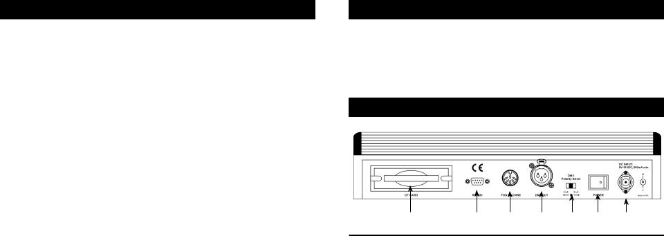
Rear Controls and Functions |
|
|
20 21 22 23 24 25 26
20.CF CARD SLOT - Insert or unload a CF Card (Compact Flash Card) which allows you to back up the memory using a 32 MB Compact Flash Card. (Not Included and Optional)
Notice: Use only a 32 MB Compact Flash Card.
21.9-Pin RS-232 CONNECTOR - The RS-232 port can be usde to connect to a personal computer in order to do memory backups and
software updates.
22.FOG MACHINE CONNECTOR - Connects to a fog machine using a 5-pin cable. Compatiable fog machines include the Master Blaster 1000, Stallion, Vaporizer™, Vapor Flow™, Fog Storm 1200™ and 1700™.
23.DMX OUT - Used to send DMX signal to fixtures or Packs.
24.DMX POLARITY SELECT - Changes the polarity setting of the DMX output.
25.POWER SWITCH - Switches the power on or off.
26.DC INPUT - Accepts a DC 9V, 500 mA minimum, power supply.
Elation Professional® www.elationlighting.com - DMX Programmer Page 3 |
Elation Professional® www.elationlighting.com - DMX Programmer Page 4 |
DMX Programmer™ |
DMX Set Up |
Power Supply: Before plugging your unit in, be sure the source voltage in your area matches the required voltage for your Elation® DMX Programmer.™ The Elation® DMX Programmer™ is 120v only. Because line voltage may vary from venue to venue, you should be sure your controller voltage matches the wall outlet voltage before attempting to operate you fixture.
DMX-512: DMX is short for Digital Multiplex. This is a universal protocol used as a form of communication between intelligent fixtures and controllers. A DMX controller sends DMX data instructions from the controller to the fixture. DMX data is sent as serial data that travels from fixture to fixture via the DATA “IN” and DATA “OUT” XLR terminals located on all DMX fixtures (most controllers only have a DATA “OUT” terminal).
DMX Linking: DMX is a language allowing all makes and models of different manufactures to be linked together and operate from a single controller, as long as all fixtures and the controller are DMX compliant. To ensure proper DMX data transmission, when using several DMX fixtures try to use the shortest cable path possible. The order in which fixtures are connected in a DMX line does not influence the DMX addressing. For example; a fixture assigned a DMX address of 1 may be placed anywhere in a DMX line, at the beginning, at the end, or anywhere in the middle. When a fixture is assigned a DMX address of 1, the DMX controller knows to send DATA assigned to address 1 to that unit, no matter where it is located in the DMX chain.
Assigning DMX Address: Each dipswitch has a preset value. A specific DMX address is set by combining the dipswitches that sum your desired value. For example: To achieve a DMX address of 7, combine dipswitches 1, 2, and 3. Since dipswitch 1 has a value of 1, dipswitch 2 has a value of 2, and dipswitch 3 has a value of 4, the combination of the three create a DMX value of 7. (See example below).
Set DMX address 1: |
Set DMX address 7: |
|
Dip-switches # 1 = 1 |
Dip-switches # 1 |
= 1 |
|
2 |
= 2 |
|
3 |
= 4 |
|
|
= 7 |
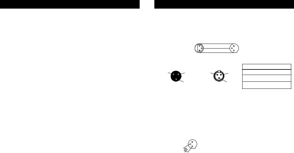
Data Cable (DMX Cable) Requirements (For DMX and Master/Slave Operation): Your DMX Programmer™ and your fixture require a standard 3-pin XLR connector for data input and data output (Figure 1). If you are making your own cables, be sure to use standard two conductor shielded cable (This cable may be purprogramd at almost all pro sound and lighting stores). Your cables should be made with a male and female XLR connector on either end of the cable. Also remember that DMX cable must be daisy chained and can not be split.
DMX Programmer™ |
DMX Set Up |
Notice: Be sure to follow figures two and three when making your own cables. Do not use the ground lug on the XLR connector. Do not connect the cable’s shield conductor to the ground lug or allow the shield conductor to come in contact with the XLR’s outer casing. Grounding the shield could cause a short circuit and erratic behavior.
|
|
|
COMMON |
|
|
|
|
DMX512 OUT |
1 |
DMX + |
3 |
1 |
DMX512 IN |
|
3 |
|
|
|||
|
3-PIN XLR |
2 |
DMX - |
|
2 |
3-PIN XLR |
|
|
|
|
|
|
Figure 2 |
XLR Male Socket |
|
XLR Female Socket |
|
XLR Pin Configuration |
||
1 Ground |
2 Cold |
|
2 Cold |
1 Ground |
Pin 1 = Ground |
|
|
|
|||||
|
|
|
|
|
|
|
|
|
|
|
|
|
Pin 2 = Data Compliment (negative) |
|
3 Hot |
|
|
3 Hot |
|
Pin 3 = Data True (positive) |
|
|
|
|
|
|
|
Figure 3
Special Note: Line Termination. When longer runs of cable are used, you may need to use a terminator on the last unit to avoid erratic behavior. A terminator is a 90-120 ohm 1/4 watt resistor which is connected between pins 2 and 3 of a male XLR connector (DATA + and DATA -). This unit is inserted in the female XLR socket of the last unit in your daisy chain to terminate the line. Using a cable terminator (ADJ part number Z-DMX/T) will decrease the possibilities of erratic behavior.
|
Termination reduces signal errors and |
|
1 |
avoids signal transmission problems |
|
3 |
and interference. It is always advisable |
|
2 |
to connect a DMX terminal, (Resistance |
|
|
120 Ohm 1/4 W) between PIN 2 (DMX-) |
Figure 4 |
|
and PIN 3 (DMX +) of the last fixture. |
5-Pin XLR DMX Connectors. Some manufactures use 5-pin XLR connectors for DATA transmission in place of 3-pin. 5-pin XLR fixtures may be implemented in a 3-pin XLR DMX line. When inserting standard 5-pin XLR connectors in to a 3-pin line a cable adaptor must be used, these adaptors are readily available at most electric stores. The chart below details a proper cable conversion.
Elation Professional® www.elationlighting.com - DMX Programmer Page 5 |
Elation Professional® www.elationlighting.com - DMX Programmer Page 6 |

DMX Programmer™ |
|
DMX Set Up |
||
|
|
|
|
|
|
3-Pin XLR to 5-Pin XLR Conversion |
|
||
|
|
|
|
|
|
Conductor |
3-Pin XLR Female (Out) |
5-Pin XLR Male (In) |
|
|
|
|
|
|
|
Ground/Shield |
Pin 1 |
Pin 1 |
|
|
|
|
|
|
|
Data Compliment (- signal) |
Pin 2 |
Pin 2 |
|
|
|
|
|
|
|
Data True (+ signal) |
Pin 3 |
Pin 3 |
|
|
|
|
|
|
|
Not Used |
|
Pin 4 - Do Not Use |
|
|
|
|
|
|
|
Not Used |
|
Pin 5 - Do Not Use |
|
|
|
|
|
|
While DMX 512 is the standard used to control lighting, at this time, there are some differences you should know about. One is pin configuration. The DATA + And DATAare reversed. This can be corrected by using the reversal switch on the DMX Programmer. If you have some fixtures from each polarity use adapter Z-DMXADAPT between the fixtures.
|
TYPE 1 |
|
TYPE 2 |
XLR MALE SOCKET |
XLR MALE SOCKET |
||
Data+ 2 |
3 Data - |
Data - 2 |
3 Data + |
|
|
||
|
1 Ground |
|
1 Ground |
|
DATA IN |
|
DATA IN |
DMX Programmer™ |
DMX Addressing |
DMX 512 is a type of protocol that sends out up to 512 multiplex channels at once down a common cable. Each channels has a value from 0 to 255. You set the address for each receiver(fixture) by using Dipswitches or some type of digital readout
Each Dipswitch has an ADDRESS based on binary code.
Dipswitch |
#1 |
#2 #3 #4 |
#5 |
#6 |
#7 |
#8 |
#9 |
||
Value |
1 |
2 |
4 |
8 |
16 |
32 |
64 |
128 256 |
|
YOU SELECT THE ADDRESS WANTED BY ADDING THE TOTAL OF DIPSWITCHES ON.
Dipswitch #10 is not used with DMX but normally to select some Function ie: Master / Slave, Sound Activation or to receive DMX Control.
Most fixtures start receiving on the address selected
Addressing Fixtures
In order to have individual control of each fixture with the DMX Programmer Fixture addresses should be addressed as follows.
Fixture Button # 1 |
starts at 1 |
Fixture Button # 2 |
starts at 9 |
Fixture Button # 3 |
starts at 17 |
Fixture Button # 4 |
starts at 25 |
Fixture Button # 5 |
starts at 33 |
Fixture Button # 6 |
starts at 41 |
Fixture Button # 7 |
starts at 49 |
Fixture Button # 8 |
starts at 57 |
If you are not sure how to set the starting address of your Fixture refer to Chart on page 23 of this manual.
Elation Professional® www.elationlighting.com - DMX Programmer Page 7 |
Elation Professional® www.elationlighting.com - DMX Programmer Page 8 |
 Loading...