Elac Miracord 50HII User guide

Page 1

Operating Instructions Miracord 50 H

AUTOMATIC TURNTABLE AND RECORD CHANGER

Page 2

INTRODUCTION

This Instruction Book for the MIRACORD 50 H Transcription Record Changer contains more than a mere description of the operating procedure. You will also find in it notes on the special properties of this instrument and the versatile facilities it incorporates.

Impatient owners may obtain a rapid run-down from the general illustration and accompanying legend at the front, subsequently turning to the remarks on installing the player and putting it into operation.

However, we recommend that the following pages also be carefully studied, as they contain information on how to effect critical adjustments, thus enabling you to obtain the ultimate performance from your records.

This is the quickest way to familiarise yourself with your MIRACORD 50 H.

And now we wish you many hours of listening pleasure and musical enjoyment.

Page 3
TABLE OF CONTENTS / ILLUSTRATIONS
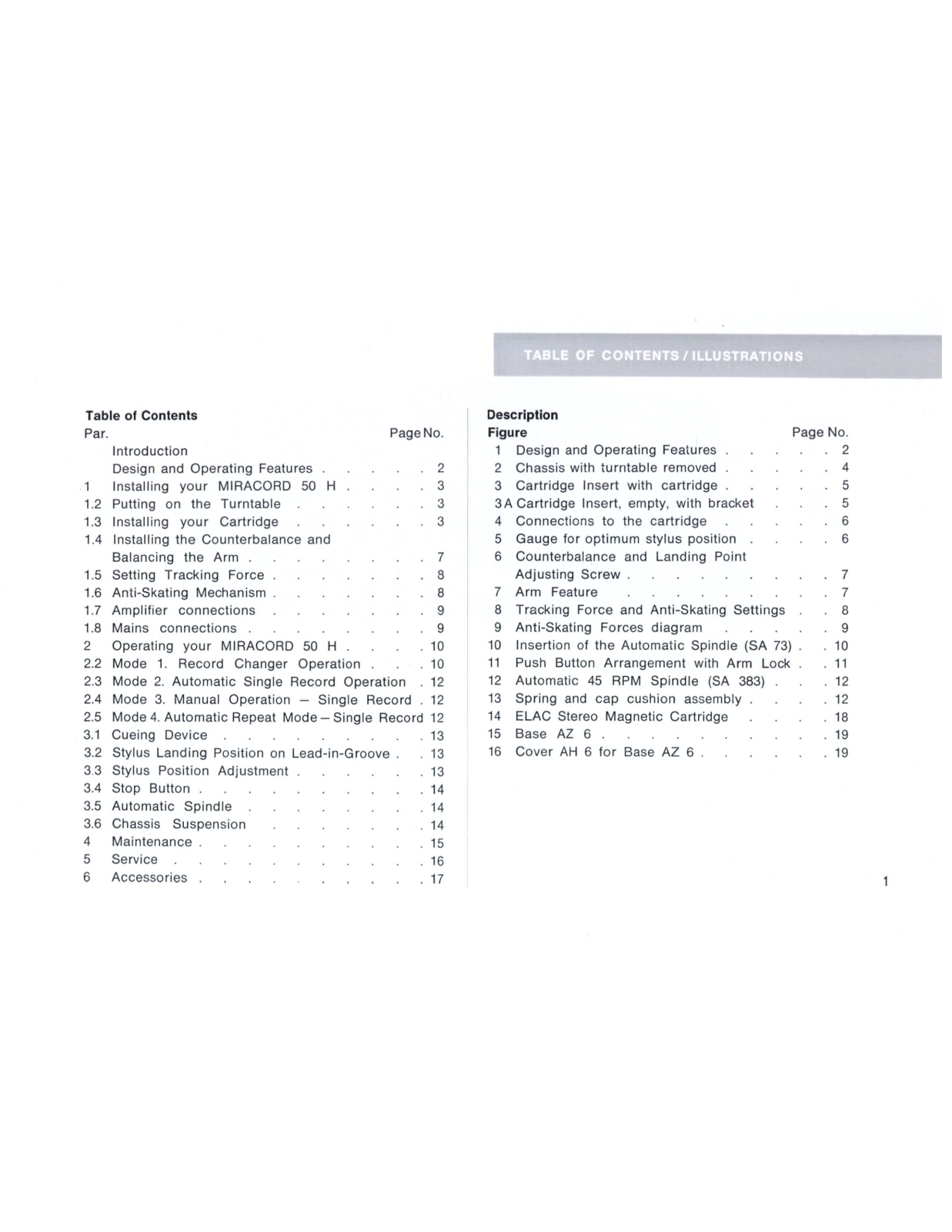
Table of Contents
Par. Page эГ 10.
Introduction
Design and Operating Features 2
1 Installing your MIRACORD 50 H З
1.2 Putting on the Turntable З
1.3 Installing your Cartridge З
1.4 Installing the Counterbalance and
Balancing the Arm 7
1.5 Setting Tracking Force 8
1.6 Anti-Skating Mechanism 8
1.7 Amplifier connections 9
1.8 Mains connections 9
2 Operating your MIRACORD 50 H 10
2.2 Mode 1. Record Changer Operation . ۰ 10
2.3 Mode 2. Automatic Single Record Operation ation 12
2.4 Mode 3. Manual Operation - Single R ecord 12
2.5 Mode 4. Automatic Repeat Mode – Single Recor d 12
3.1 Cueing Device 13
3.2 Stylus Landing Position on Lead-in-Groom ve. 13
3.3 Stylus Position Adjustment 13
3.4 Stop Button 14
3.5 Automatic Spindle 14
3.6 Chassis Suspension 14
4 Maintenance 15
5 Service 16
6 Accessories 17

Description

Figu lre Page e r 10.
1 Design and Operating Features 2
2 Chassis with turntable removed 4
З Cartridge Insert with cartridge 5
ЗA Cartridge Insert, empty, with bracket 5
4 Connections to the cartridge 6
5 Gauge for optimum stylus position . 6
6 Counterbalance and Landing Point
Adjusting Screw 7
7 Arm Feature 7
8 Tracking Force and Anti-Skating Settin gs 8
9 Anti-Skating Forces diagram 9
10 Insertion of the Automatic Spindle (SA 73) 10
11 Push Button Arrangement with Arm Lo ock 11
12 Automatic 45 RPM Spindle (SA 383) 12
13 Spring and cap cushion assembly . 12
14 ELAC Stereo Magnetic Cartridge . 18
15 Base AZ 6 19
16 Cover AH 6 for Base AZ 6 19
Page 4

Design and Operating Features

1 Mounting Assemblies (Spring, cushion and 10 Counterbalance
support) 10 A Counterbalance vernier adjustment
2 Speed Change Lever 11 Cueing Lever
3 Turntable 12 Arm Lock (red indicator showing "locked
4 Mat position", green "unlocked position")
5 Center Plate 13 Stop Button
6 Spindle Shaft with Automatic Spindle SA 73 14 A, B, C 12", 10" and 7" Buttons
(6 A) 15 Cartridge Insert
7 Tone Arm 16 Stylus position adjustment gauge
8 Anti-Skating Control 17 Stylus position adjustment screw
9 Tracking force adjustment dial 18 Speed Indicator and Pilot Light
9 A Balance Hairline Indicator 19 Single-play Spindle
Page 5
. INSTALLING YOUR MIRACORD 50 H
1.1

You may support your MIRACORD on a standard base or mounting board designed for this purpose or make your own support in a cabinet or drawer. If you use the standard base or mounting board, the record changer can be easily mounted by slowly lowering the chassis and inserting the springs (in their sound and shock absorbing rubber supports) in the four holes provided. Follow the instructions on the enclosed template (17 452 9705), which gives you the exact size of the cutout necessary as well as the dimensions of the mounting holes. Using a screwdriver or coin, the lower threads of the screws 4 are now screwed clockwise through the bushes 1 so as to leave the plain, unthreaded part of the screws loose inside the bushes and the chassis free to move on the springs. This is the playing position of the unit.

1.11

After placing the mechanism in its support, make sure the record changer is free to move on its springs in all directions. Check the push-button operation to see that no parts bind on the wood board or base and that the lead wires are not drawn so tightly as to restrict the movement of the changer.

1.12

If it is necessary to transport or ship your MIRACORD after it has been installed, secure it to the base or

mounting board by means of the transport locks indicated on the template. This is done by tightening the screws 4 above the bushes 1 so that the chassis springs 6 are compressed and the chassis rests firmly on the bushes 1. Fasten the arm by means of the arm lock (Fig. 1–12, position red). The heavy cast turntable should always be packed separately and should never be shipped on the mechanism. Disconnect the unit before carrying out mounting works on the chassis.

1.2 Putting on the Turntable

Before putting on the turntable, move lever 21 with its associated spring (Fig. 2) sideways since it may be close to the cone bearing on which the turntable will be mounted. Make sure that the turntable is not placed inadvertently on the idler wheel. To do this, place the tone arm on its support and move the movable idler wheel inwards before putting on the turntable. Place the turntable on the cone of the turntable shaft. Do this carefully and gently, since otherwise the ball bearing might be damaged. Finally, put on the rubber mat making sure that the center hole is firmly pressed around the center raised portion of the heavy turntable. Center the metal cover plate (Fig. 1–5) on the rubber mat.

1.3 Installing your Cartridge

The standard accessories include the cartridge insert

Page 6

Fig. 2

Page 7

(Fig. 1-15) with the ELAC Stereo Magnetic Cartridge already mounted (Fig. 3). This insert should be pushed on to the tone arm (Fig. 1-7) up to the stop, whereby the cartridge terminals are automatically connected to the tone arm leads. The cartridge insert is best fitted with the arm horizontal.

1.31

Should a different cartridge be fitted, the correct procedure is as follows: The cartridge insert (Fig. 3A) contains a slide with two threaded holes to accept the cartridge. If the latter has its own bracket, this is secured with the aid of the threaded holes. If not, the cartridge itself is fitted to the insert, which is dimensioned to accept all cartridges with standard fixing holes. In mounting the cartridge be sure the stylus protrudes sufficiently below the lower edge of the cartridge insert to properly play either one or a stack of records. If the small spacers supplied do not give enough clearance, use the large spacers enclosed with the cartridge mounting hardware. The final position of the stylus (forward or backward) will be adjusted later (Par. 1.33).

1.32

The respective ground wires for each channel are connected to the terminals marked "O" adjacent to the R and L terminals.

The cartridge insert has four wires and requires no separate or fifth wire connected to ground. The proper connection of these four wires is shown in Fig. 4 (as shown with ELAC STS 344 cartridge). You can connect the

Page 8

wires for either mono or stereo reproduction as shown. For stereo reproduction the R (right) channel should be connected to the R (right) pin on your cartridge and similarly the L (left channel) should be connected. For mono reproduction the two channels of a stereo cartridge may be connected in parallel or series.

1.33 Adjustment of the cartridge

There is an optimum position of the stylus with respect to the tone arm for every mechanism. If this optimum position is not used, tracking error will increase considerably. The MIRACORD 50 H is provided with a gauge which enables you to adjust the position of the cartridge after it has been installed and set it in the optimum position. This is done by means of the adjusting screw in the front of the cartridge insert (Fig. 5–17) and the gauge located on the chassis plate under the cartridge insert (Fig. 5-16). Turning the screw clockwise will move the entire cart-

ridge forward - counter-clockwise turns will move it backward. Set the position by lifting the gauge up to the stylus S itself (Fig. 5). If the stylus does not line up with the tip of the gauge, turn the adjusting screw until it is exactly in position. (For further description and explanation of this feature see Par. 3.3).

1.34 Stylus Landing Position on Record

Adjustment is made after having set the stylus force according to Par. 3.2.

Fig. 5

Page 9

1.4 Installing the Counterbalance and Balancing the Arm 1.41

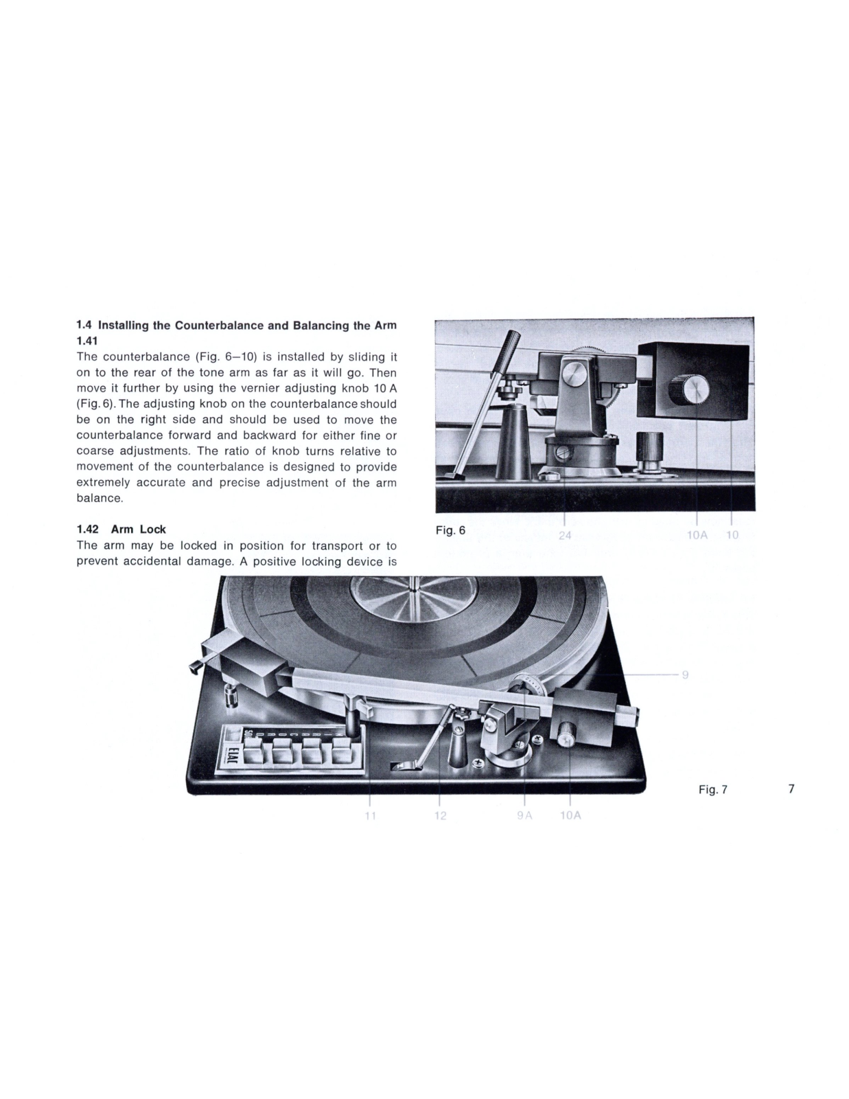
The counterbalance (Fig. 6–10) is installed by sliding it on to the rear of the tone arm as far as it will go. Then move it further by using the vernier adjusting knob 10 A (Fig. 6). The adjusting knob on the counterbalance should be on the right side and should be used to move the counterbalance forward and backward for either fine or coarse adjustments. The ratio of knob turns relative to movement of the counterbalance is designed to provide extremely accurate and precise adjustment of the arm balance.

1.42 Arm Lock

The arm may be locked in position for transport or to prevent accidental damage. A positive locking device is

Fig. 7

Page 10

provided with clear indication of locked (red) and unlocked (green) positions (Fig. 7–12). If by chance an operating button is depressed while the arm is locked, a unique mechanism prevents damage to the mechanism while the changer automatically recycles and stops.

1.43 Balancing the arm (Arm lock [Fig. 7–12] in open [green] position)

After the cartridge has been installed and finally positioned, and the counterbalance has been inserted as above, you are ready to balance the arm. This is done with the stylus force adjustment dial (Fig. 7–9) set at zero. The hairline marking on the arm bearing (Fig. 7-9A) must now be lined up with the zero mark. Move the counterbalance backward or forward by means of the adjusting knob (Fig. 7–10A) until the tone arm is in perfect balance.

1.5 Setting Tracking Force

This force, which is the pressure the stylus exerts on the record, is easily set on MIRACORD 50 H by means of a direct reading dial (Fig. 8–9). It can be set for a minimum of 1/2 gram to 6 grams. Select the gram pressure recommended by the cartridge manufacturer. Then set the tracking force desired by turning the dial to the proper reading opposite the hairline on the bearing (Fig. 8–9A).

1.6 Anti-Skating Mechanism

Your MIRACORD 50 H incorporates a device to counteract the side force exerted on the stylus as it moves

toward the center of the record. While this force is extremely small, it can cause the needle to "skate" toward the center of the record at very low stylus forces, or introduce a very slight distortion due to unequal stylus pressure on the wall of the record groove.

1.61

Fig. 9 shows the operation of the anti-skating mechanism. The skating force exerted on the stylus is balanced by a counteracting force A. The value of the counteracting force can be varied by tightening a rotary spring with the aid of knob 8 and is transferred via a lever H to the bolt B on the tone arm shaft.

Page 11

1.62

As revealed by thorough tests the force exerted on the stylus toward the center depends on the value of the stylus force. The anti-skating mechanism is designed in such a way that the skating force is compensated if the anti-skating knob (Fig. 8–8) is adjusted to the exact setting of the stylus force. For example: With 2 g stylus force set red point on knob 8 to position 2.

1.7 Amplifier Connections

The MIRACORD 50 H is provided with a 2-wire screened connecting lead which normally has a five-pin round plug

DIN 41524, but can also be supplied, on special order, with a one-pin coax plug for both channels. If it is intended to use the player with a stereo radio receiver or an amplifier with a low-sensitivity input and no equalization network, facilities are provided for inserting the PV 9 equalizer preamplifier under the chassis plate (see Par.6). The preamplifier incorporates the necessary equalizer network for compensating the recording characteristic. It must be ordered as an accessory and is supplied at extra cost. If no preamplifier is used, the terminals in the spring contact strip provided for it underneath the chassis are short-circuited by a shorting strip.

1.8. Mains Connections

The MIRACORD 50 H is supplied for connection to 110/ 115 V, 60 cps A.C. or 220/240 V, 50 cps A.C. The correct mains voltage and frequency are shown on the data plate under the turntable. Subsequent conversion to another voltage or frequency is possible by exchanging the motor with phase condenser respectively. When carrying out such a conversion, it must be borne in mind that the PV 9 preamplifier, if present, must also be adapted to the new voltage and/or frequency. Further details will be found in the Mounting Instructions for the PV 9 preamplifier (B 2–700 D E F).

Caution:

The heavy outer rotor of the hysteresis motor is secured for shipment by 2 plastic wedges. Be shure to remove these wedges before plugging the unit into the power socket.

Page 12
2. OPERATING YOUR MIRACORD 50 I

2.1

Altough there are four different modes of operating your MIRACORD, depressing a single button is all that is necessary most of the time. These four modes are described in detail below, but before playing a record set the speed as described below, and release the arm by switching the arm lock (Fig. 11–12) to the green position.

2.11 Speed

Your MIRACORD 50 H is designed to operate at all four speeds (78, 45, 331/3, and 162/3 RPM). The speed is set with the lever at the extreme left (Fig. 1–2) and the speed selected is shown in the illuminated window (Fig. 1–18). It will only be illuminated when power is applied to the motor.

Note:

The hysteresis motor of the MIRACORD 50 H is designed to provide extremely accurate rotation of the turntable at the speed selected regardless of the line voltage, so that no further adjustment for speed is necessary.

2.2 Mode 1. Record Changer Operation

Use long Automatic Spindle SA 73 (10–6A) and insert the pointed end in the hollow center (6) of the turntable (Fig. 10–6). Automatic play is possible for either 7", 10" or 12" records. Up to 10 records of the same size can be played

Fig. 10 6A 6

Page 13

in sequence. (For automatic play of 7" records with a large center hole, use accessory automatic spindle SA 383 [Fig. 12]). To start the record changer, lightly depress the button corresponding to the diameter of the records being played (i. e. for 12" records use the button marked 12). After the button is pushed, the turn-table will start turning, the first record will drop, and the arm will lift and lower the stylus gently onto the lead-in groove of the record. At the conclusion of the first record will drop, and the cord will drop, and the cord will drop, and the cycle will be repeated. At the conclusion of the last record in the stack, the arm will lift and return to the rest, the next record will a brake (Fig. 2–27) is applied to stop the turn-table.

Note:

To add records while the record changer is in automatic operation, be sure that at least one record is still on the Automatic Spindle. If there is no record on the spindle and an additional record is placed on the arm of the spindle, the mechanism will drop this record but will not play it. It will be necessary to depress the appropriate button again to play this record.

2.21

To remove the records after the last record has dropped and has been played, remove the "Automatic" Spindle from the shaft by lifting it up vertically and then remove the stack of records. This prevents undue wear on the center hole of the records.

Fig. 11

Page 14

2.3 Mode 2. Automatic Single Record Operation

Use short spindle (Fig .1–19) (inserted point down). An individual record can be played automatically (without handling the arm) by using the small spindle and placing the record on the turntable, then lightly depress the button corresponding to the size of the record. The turntable will start rotating, the arm will lift, and the stylus will be gently lowered onto the lead-in groove of the record. At the conclusion of the record the arm will shut off and the brake will be actuated.

2.4 Mode 3. Manual Operation – Single Record

Use short spindle (point down). Manual operation of the MIRACORD 50 H is a very simple operation. Place the record on the short spindle as in 2.3 above, then lift the arm by means of the finger-grip and place it on the desired groove of the record. As soon as the arm is lifted the turntable will start rotating and the unit is ready to play. At the end of the record the arm will lift and return to rest and the mechanism will shut off, and the brake will be actuated.

Note:

As in all modes of operation, the arm may be lifted off the record at any time and returned to the rest or placed on another groove of the record without disturbing the mechanism.

2.5. Mode 4. Automatic Repeat Mode – Single Record Use short spindle ( inserted point up ). A record of any

size can be played over and over again by inserting the short spindle with the point up. The mechanism must be started by depressing the button corresponding to the size of the record being played. At the conclusion of the record the arm will lift and return to the start of the record and replay it. This will continue until the "Stop" button is depressed or the arm is lifted off the record manually and returned to the rest.

12

Fig. 14

Page 15

3. SPECIAL FEATURES OF THE MIRACORD 50 H

3.1 Cueing Device (Fig. 7–11)

Frequently it is desired to play a specific band of a record. This can be very simply accomplished with the Cueing Device (Fig. 7-11). This mechanism constists of a platform which supports the tone arm and stylus a short distance above the record when the Cueing Lever is moved forward (v). When the arm is moved by hand to the desired position so that the stylus is directly over the band to be played, moving the lever back will lower the stylus very slowly and gently onto the record ( v ). The arm can be lifted off the arm rest either by depressing the appropriate button (Par. 2.3) or by hand (Par. 2.4). The lever can be moved forward at any time, and will lift the stylus off the record and hold it at that point until moved by hand or by moving the lever back again. Do not move lever forward (lifting) when the tone arm is still locked.

3.2 Stylus Landing Position on Lead-in Groove of Record

This adjustment has already been made at the factory with an ELAC cartridge. If you have installed a different type of cartridge, a readjustment may be necessary. Connect the unit to A.C. power source (see Par. 1.8), set the desired speed of the turntable with the speed change lever (Fig. 1–2) and place a 7", 10" or 12" record on the turntable. Release the arm lock (Fig. 11–12) by switching

to the green position. Start the record changer by depressing the corresponding start button (7", 10" or 12"). The turntable will start to rotate, the tone arm will lift off its support and swing inwards and lower itself into the starting groove of the record. If necessary, correct the landing point of the stylus by turning slotted screw (24) (Fig. 6–24) on the tone arm socket. Turning screw clockwise moves the landing point outward, counter - clock wise—inward.

3.3 Stylus Position Adjustment

A very slight difference in the position of the stylus with respect to the tone arm bearing can result in a large increase in the error introduced in tracking. This is due to the fact that the arm is in a different position with respect to the record at the beginning of the record and at the end of the record. There is an optimum position which is determined by the geometry of the mechanism, depending on the length of the tone arm, the distance from the center of the record, etc. This optimum position has been carefully calculated for your MIRACORD 50 H. A gauge (Fig. 5–16) has been provided locating the exact point the stylus should be at for this optimum setting. To provide a means of moving the cartridge and stylus back and forth, a special mechanism has been built into the cartridge insert. The adjusting screw

Page 16

(Fig. 5-17) moves the cartridge forward and backward laterally along the arm. When the stylus is positioned directly above the gauge, it is in its optimum position.

3.4 Stop Button (Fig. 11-13)

You will notice a fourth button on the chassis directly above the three operating buttons which are marked with the record size. This button is marked "Stop" and is used to interrupt the playing of a record or stack of records at any time. When depressing during play, it will lift the arm off the record and return it to the arm rest and shut off the mechanism. To resume play, you can depress the stop button again, and the record already on the turntable will be replayed. To drop the next record, it is necessary to depress the appropriate operating button.

3.5 The "Automatic" Spindle

The unsupported record spindle SA 73 for records with standard center hole represents a recognized breakthrough in the technique of record changing. It supports

your records in three places and provides for the most gentle dropping action ever devised for a record changer. For changing 7" records with 38 mm center hole, a special accessory, the SA 383 spindle (Fig. 12 and Par. 5.2) is available to order. This is exchanged for the SA 73 record spindle when required.

3.6 Freely Supported Chassis Suspension

The chassis rests on four soft cone shaped springs with plastic cups (Fig. 13) which have the important function of preventing acoustic feedback between the loudspeakers and the cartridge. The springs are packed with foam rubber in order to cancel oscillations caused by vibrations. The copper-plated spring, seated close to the push-buttons underneath the chassis is stronger than the three others so that the chassis rests in horizontal position. When shipping the unit, the installed chassis must be secured by additional screws to prevent it from moving sideways. Further details are to be found in the enclosed mounting board template.

Page 17
4. MAINTENANCE

Your Studio Series MIRACORD is designed by the factory to require practically no lubrication during its life. Neither the motor nor turntable bearings should be lubricated, since they are provided with proper long life lubricants at the factory. Under extraordinary conditions where your unit has been subjected to extremes of dust and dryness, it is suggested that you have your local MIRACORD dealer service the unit.

Great care should be used any time the turntable is lifted off the mechanism and the idler wheel is exposed, to prevent oil or grease from reaching the rubber rim or inside rim of the turntable. If the idler wheel is noisy for any reason, a small drop of light machine oil may be care-

fully placed on the idler wheel bearing. Be sure to wipe off any excess oil from the rim with alcohol.

4.2

The needle of the pickup cartridge must always be free of dust. Diamond styli can be used for about 1000 hours of playing. However, despite their hardness, they abrade gradually. Worn needles impair sound reproduction and damage record grooves. The needle should be replaced in due time. A defective needle should be replaced immediately. Stylus exchange is an extremely simple matter, as shown by the example of the ELAC cartridge STS 344 (Fig. 3).

Page 18

Should your MIRACORD 50 H require servicing, it is suggested that you call on your local MIRACORD dealer or ask him for the address of the nearest MIRACORD Service Station. If shipping the unit is required it is impor-

tant to use the original carton with the corresponding inserts to avoid shipping damage. The following hints are applicable for minor repairs:

Sympton Cause Remedy Turntable does not start when 1. No voltage at motor. See that unit is plugged into live AC 7", 10" or 12" button is depressed. outlet. 2. Line switch defective. Replace line switch. 3. Motor defective. Replace motor. Replace stylus. Arm skips across record. Defective stylus. Distorted sound. 1. Defective stylus. Replace stylus. 2. Improper setting of stylus force dation for correct stylus force and Uneven speed. 1. Oil or grease on idler tire. Clean rim of turntable and idler tire with alcohol. 2. Defective idler tire.

No sound from speaker.

  • 1. Defective cartridge.
  • 2. Defective output leads.
  • 3. Improper connection to amplifier or preamp.

Consult manufacturer's recommen-

adjust unit to this value. See Par. 1.5.

Replace idler wheel.

Replace cartridge.

Replace output leads.

Check input leads to amplifier or preamp making sure that proper electrical connection is achieved.

Page 19
6. ACCESSORIES

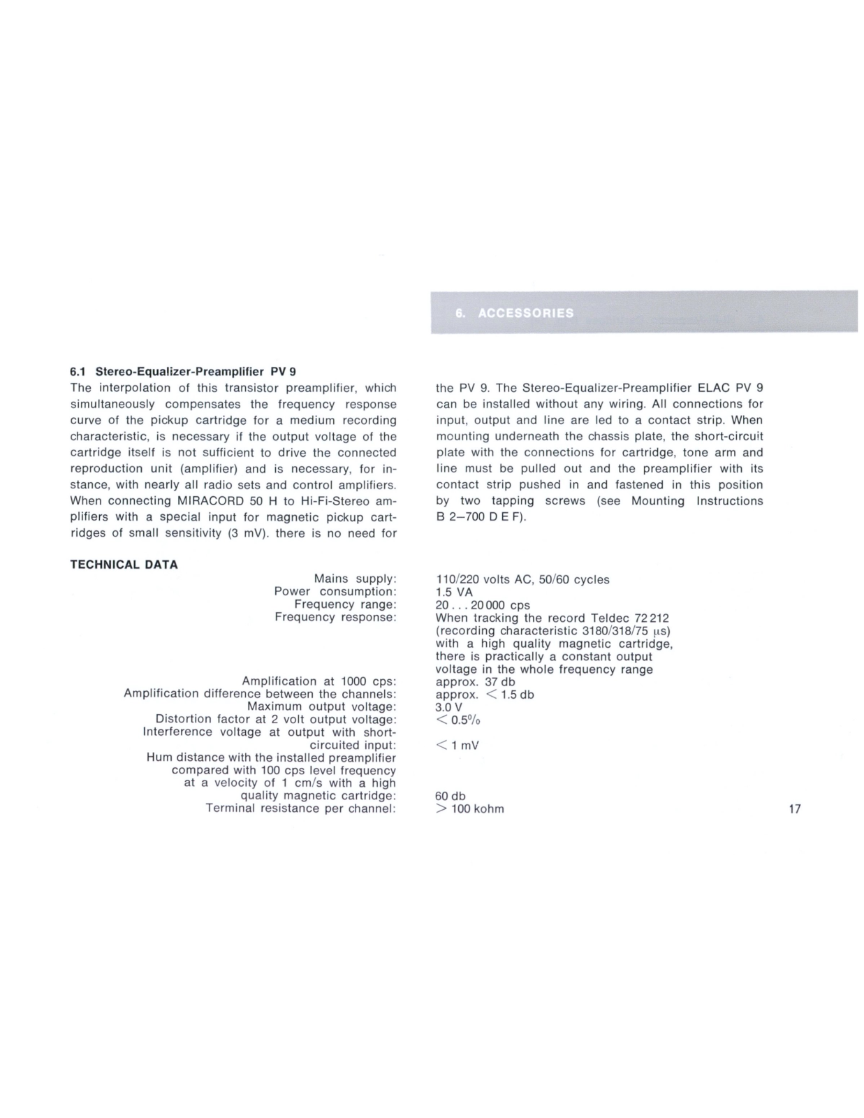
6.1 Stereo-Equalizer-Preamplifier PV 9

The interpolation of this transistor preamplifier, which simultaneously compensates the frequency response curve of the pickup cartridge for a medium recording characteristic, is necessary if the output voltage of the cartridge itself is not sufficient to drive the connected reproduction unit (amplifier) and is necessary, for instance, with nearly all radio sets and control amplifiers. When connecting MIRACORD 50 H to Hi-Fi-Stereo amplifiers with a special input for magnetic pickup cartridges of small sensitivity (3 mV), there is no need for

TECHNICAL DATA

Mains supply: Power consumption: Frequency range: Frequency response:

Amplification at 1000 cps: Amplification difference between the channels: Maximum output voltage: Distortion factor at 2 volt output voltage: Interference voltage at output with shortcircuited input: Hum distance with the installed preamplifier compared with 100 cps level frequency at a velocity of 1 cm/s with a high quality magnetic cartridge: Terminal resistance per channel:

the PV 9. The Stereo-Equalizer-Preamplifier ELAC PV 9 can be installed without any wiring. All connections for input, output and line are led to a contact strip. When mounting underneath the chassis plate, the short-circuit plate with the connections for cartridge, tone arm and line must be pulled out and the preamplifier with its contact strip pushed in and fastened in this position by two tapping screws (see Mounting Instructions B 2–700 D E F).

110/220 volts AC, 50/60 cycles 1.5 VA 20...20000 cps When tracking the record Teldec 72212 (recording characteristic 3180/318/75 μs) with a high quality magnetic cartridge, there is practically a constant output voltage in the whole frequency range approx. 37 db approx. < 1.5 db 3.0 V < 0.50/0

< 1 mV

60 db > 100 kohm

Page 20
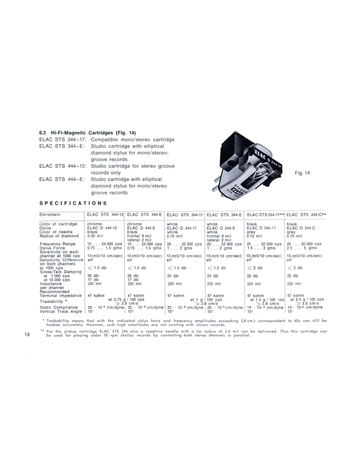
6.2 Hi-Fi-Magnetic Cartridges (Fig. 14)

ELAC STS 344–17: Compatible mono/stereo cartridge ELAC STS 344–E: Studio cartridge with elliptical diamond stylus for mono/stereogroove records ELAC STS 444–12: Studio cartridge for stereo groove records only ELAC STS 444–E: Studio cartridge with elliptical diamond stylus for mono/stereo

aroove records

Fig. 14

SPECIFICATIONS

Stereotwin ELAC STS 444-12 ELAC STS 444-E ELAC STS 344-17 ELAC STS 344-E ELAC STS 244-17** ELAC STS 244-C**
Color of cartridge
Stylus
Color of needle
Radius of diamond
chrome
ELAC D 444-12
black
0,50 mil
chrome
ELAC D 444-E
black
frontal 9 mil
lateral 2 mil
white
ELAC D 344-17
white
0.70 mil
white
ELAC D 344-E
white
frontal 9 mil
black
ELAC D 244-17
grey
0.70 mil
black
ELAC D 244-C
grey
0.70 mil
Frequency Range
Stylus Force
Sapsitivity on each
10 24.000 cps
0.75 1.5 gms
10 24.000 cps
0.75 1.5 gms
20 22 000 cps
1 2 gms
20 22 000 cps
1 2 gms
20 20 000 cps
1.5 3 gms
20 20 000 cps
2.5 5 gms
channel at 1000 cps
Sensitivity Difference
10 (mV/10 cm/sec)
eff
10 (mV/10 cm/sec)
efi
10 (mV/10 cm/sec)
eff
10 (mV/10 cm/sec)
eff
15 (mV/10 cm/sec)
eff
15 (mV/10 cm/sec)
eff
at 1000 cps
Cross-Talk Damping
< 1.5 db < 1.5 db < 1.5 db < 1,5 db < 2 db < 2 db
at 1 000 cps 26 db
17 db
26 db
17 db
24 db 24 db 22 db 22 db
Inductance
per channel
Recommended
320 mh 320 mh 320 mh 320 mh 320 mh 320 mh
Terminal Impedance 47 kohm 47 kohm 47 kohm 47 kohm 47 kohm 47 kohm
Trackability * at 0.75 g g / 100 cps
8 cm/s
at 1 g / 100 cps
8 cm/s
at 1.5 g / 100 cps at 2.5 g / 100 cps
Static Compliance
Vertical Track Angle
33 · 10 6 cm/dyne
15°
33 · 10 -6 cm/dyne
15°
25 · 10 · 6 cm/dyne
15°
25 · 10 -6 cm/dyne 18 · 10 · 6 cm/dyne
15°
10 · 10-6 cm/dyne
15°

* Trackability means that with the indicated stylus force and frequency amplitudes exceeding 3,8 cm/s correspondent to 60μ can still be tracked accurately. However, such high amplitudes are not existing with stereo records.

** For the pickup cartridge ELAC STS 244 also a sapphire needle with a tip radius of 2.6 mil can be delivered. Thus this cartridge can be used for playing older 78 rpm shellac records by connecting both stereo channels in parallel.

Page 21

6.3 Extras

Mounting Base AZ 6 (Fig. 15) Plastic Cover AH 6 (Fig. 16)

Fig. 15

Fig. 16

We reserve the right to make changes due to technical improvements.

Page 22

Page 23

Page 24

17 452 9741 3 50 3 69 Printed in West Germany

Page 25

Fig. 1

Fig. 2

Page 26

Einbauanleitung MIRACORD 50 H und MIRAPHON 22 H in Zarge AZ 6

In der Zarge befinden sich folgende Teile zur Befestigung von Laufwerk, Netz- und Tonabnehmer-Anschlußleitung:

2 Gewindebuchsen 17 066 5190 1 Zylinderschraube 04 01 1 0054
2 Muttern 17 066 5191 1 Scheibe 04 34 1 0010
2 Federscheiben 17 066 5205 1 Klemmblech 11 09 8 5004
1 Isolierstück 11 09 8 5005

1. Einbau des Chassis

Man führt die Netzanschlußleitung und die Tonabnehmer-Anschlußleitung von innen durch das große Loch im Zargenboden unter Klemmblech und Isolierstück hindurch nach außen. Nun setzt man das Chassis ohne Plattenteller von oben in den Holzausschnitt ein, und zwar so, daß die Chassis-Federn mit ihren Kunststoff-Ansätzen in die Löcher K kommen (Fig. 1 b) und die Schrauben 4 genau über den Buchsen 1 stehen (Fig. 1).

Nun werden mit einem Schraubenzieher oder einer Münze das untere Gewinde der Schrauben 4 ganz durch die Buchsen 1 gedreht (im Uhrzeigersinn), so daß sich nun der gewindefreie Teil der Schrauben ohne Berührung innerhalb der Buchse befindet und das Chassis frei beweglich auf den Federn ruht. Dies ist die Arbeits- d.h. Spielstellung des Gerätes. Der Plattenteller kann nun aufgesetzt und das Gerät an das Netz und den Verstärker angeschlossen werden.

2. Transportsicherung

Man zieht den Netzstecker aus der Dose und nimmt den Plattenteller ab. Das Chassis wird mit der Hand fest gegen die Holzgrundplatte gepreßt, so daß die Chassisfedern zusammengedrückt werden. Dann dreht man mit Münze oder Schraubenzieher bei beiden Schrauben nacheinander das obere Gewinde bis zum Anschlag ein. Das Chassis sitzt nun fest auf der Grundplatte. Der schwere Plattenteller darf während des Transportes nicht aufgesetzt sein. Er muß gesondert verpackt werden.

3. Lösen der Transportsicherung

Vor Anschluß und Inbetriebnahme muß die Sicherung unbedingt gelöst werden, da sonst Rumpelstörungen auftreten. Man dreht (entgegen dem Uhrzeigersinn) den oberen Gewindeteil der Schrauben aus den Buchsen heraus, so daß sich das Chassis anhebt und nun wieder frei schwingend auf den Federn ruht. Danach wird der Plattenteller wieder aufgesetzt.

4. Ausbau des Chassis

Netzstecker ziehen und Plattenteller abheben. Unteres Gewinde der Schrauben aus den Buchsen herausdrehen und Chassis aus dem Ausschnitt herausheben.

Page 27

Instructions for Mounting the MIRACORD 50 H and MIRAPHON 22 H on Base AZ 6

The base contains the following parts for fixing the turntable, mains cord and pickup lead:

2 Threaded bushes 17 066 5190 1 Cylindrical screw 04 011 0054
2 Nuts 17 066 5191 1 Washer 04 341 0010
2 Spring washers 17 066 5205 1 Clip 11 098 5004
1 Insulator 11 098 5005

1. Mounting the chassis

Pass the mains cord and pickup leads through the cutout via the clip and insulator and out through the large hole in the base bottom. The chassis, without the turntable, can now be lowered into the cutout in such a way that the springs with their plastic extensions locate in the holes K (Fig. 1 b) and the screws 4 are exactly above the bushes 1 (Fig. 1).

Using a screwdriver or coin, the lower threads of the screws 4 are now screwed clockwise through the bushes 1 so as to leave the plain, unthreaded part of the screws loose inside the bushes and the chassis free to move on the springs. This is the playing position of the unit. The turntable can now be mounted in place and the necessary connections made to the mains and amplifier.

2. Transport lock

Remove the mains plug from the socket and take off the turntable. Press the chassis with the hand against the wooden base plate so as to compress the chassis springs. Then with a screwdriver or coin, tighten the upper threads of both screws up to the limit. The chassis is now firmly screwed to the base plate. The turntable must not be attached in transit, but should be packed separately.

3. Releasing the transport lock

Before connecting up and operating the record player, it is imperative for the transport lock to be released, otherwise reproduction will be affected by rumble. Unscrew the upper threads of the locking screws (counter-clockwise) out of the bushes, so that the chassis rests freely and resiliently on the springs. Finally, remount the turntable.

4. Detaching the chassis

Remove the mains plug and take off the turntable. Unscrew the lower threads of the locking screws out of the bushes and lift the chassis out of the cutout.

Page 28

Instructions pour le montage des MIRACORD 50 H et MIRAPHON 22 H sur le support AZ 6

Dans le support il y a les pièces suivantes destinée à la fixation de l'appareil, cordons réseau et de raccordement de pick-up:

2 douilles filetées 17 066 5190 1 vis cylindrique 04 011 0054
2 écrous 17 066 5191 1 rondelle 04 341 0010
2 rondelles élastiques 17 066 5205 1 serre-fil 11 098 5004
1 pièce isolante 11 098 5005

1. Montage du chassis

Faire sortir le cordon réseau ainsi que le cordon de raccordement du pick-up par le grand trou existant dans le fond du support, en les passant sous le serre-fil et la pièce isolante. Introduire maintenant le chassis – le plateau ayant été préalablement enlevé – par le haut, dans la découpe, de manière telle que les ressorts du chassis avec leurs épaulements en matière synthétique viennent dans les trous K (Fig. 1 b), tandis que les vis 4 se trouvent exactement au droit des douilles 1 (Fig. 1).

Cela étant, en se servant d'une tourne-vis ou d'une pièce de monnaie, visser complètement les vis 4 au travers des douilles 1 (dans le sens des aiguilles d'une montre), de manière à ce que la partie non filetée des vis passe dans les douilles et soit sans contact avec celles-ci; d'autre-part, le chassis doit pouvoir osciller librement sur les ressorts. Cette position est la position de travail de l'appareil, c'est-à-dire sa position d'audition. Mettre en place le plateau et raccorder l'appareil au réseau et à l'amplificateur.

2. Sécurités de transport

Débrancher l'appareil du réseau et enlever le plateau. Maintenir ferment le chassis contre l'embase de manière à comprimer les ressorts du chassis. En se servant d'une pièce de monnaie ou d'un tourne-vis, visser successivement les deux vis transporter l'appareil avec son lourd plateau en place. Il y a lieu d'emballer séparément le plateau.

3. Enlèvement des sécurités de transport

Il est indispensable d'enlever les sécurités de transport avant raccordement et mise en service, vu le risque de bourdonnements. Pour ce faire, dévisser (agir en sens inverse des aiguilles d'une montre) le filet supérieur des vis hors des douilles, de manière à ce que le chassis se soulève et repose à nouveau librement sur les ressorts. Remettre ensuite le plateau en place.

4. Démontage du chassis

Débrancher du réseau et enlever le plateau. Dévisser le filet inférieur des vis hors des douilles et retirer le chassis de la découpe.

Page 29

Anleitung zum Nadelwechsel

für Original - ELAC - Ersatznadeln D 144—17, S 244—65, D 244—17, D 244—C, D 244—G, D 244—E, D 344—17, D 344—E, D 444—12, und D 444—E.

Zum Nadelwechsel erfaßt man die Abtastnadel am Kunststoff-Bügel und zieht diese, wie in der Abbildung dargestellt, aus dem System heraus.

Die Abtaststifte müssen in größeren Zeitabständen geprüft werden. Gesplitterte und abgenutzte Abtaststifte beschädigen die Platte. Außerdem ist darauf zu achten, daß der Stift immer frei von Staub bleibt. Zur Reinigung empfehlen wir einen weichen Pinsel.

Diamantstifte haben bei pfleglicher Behandlung eine Lebensdauer von ca. 1 000 Betriebsstunden. Die empfohlene Auflagekraft für die verschiedenen Nadeln ist aus nachstehender Tabelle zu ersehen:

D 144-17 S 244-6 5 D 24 44-17
1.5 3 g 2.5 5 g 1.5 3 g
D 244-C D 244-G D 244-E D 344-17
2.55g 1.53g 1.5 3 g 12g
D 344-E D 444-12 D 444 -E
12g 0.75 1.5 g 0 .75 1.5 g

Überschreiten des Maximalwertes ändert die Nadel-Geometrie unzulässig und kann zur Beschädigung der Schallplatte führen. Minimalwert nur anwendbar, wenn Eigenschaften von Laufwerk und Schallplatte dies zulassen.

Instructions for Changing Styli

For original ELAC replacement styli D 144—17, S 244—65, D 244—17, D 244—C, D 244—G, D 244—E, D 344—17, D 344—E, D 444—12, and D 444—E.

To remove old stylus, grip by plastic stirrup and draw out of cartridge as shown in illustration. Insert new stylus accordingly.

The stylus should be inspected at regular intervals. Chipped and worn styli damage records. Also, the stylus tip should always be kept free of dust and fluff. A soft brush is recommended for cleaning.

With reasonable care diamond styli have a life of about 1 000 playing hours. The recommended stylus force for the various styli is given in the following table:

D 144-17 S 244-6 5 D 244-17
1,53 p 2,5 5 p 1,53p
D 244-C D 244-G D 244-E D 344-17
2,55p 1,53 p 1,5 3 p 0 12p
D 344-E D 444-12 D 444-E
12p 0,75 1,5 p 0,7 75 1,5 p

If the above limits are exceeded, the stylus geometry is altered to an unpermissible extent and damage to records may result. The lower limit is applicable only if the characteristics of the turntable and record are suitable.

Page 30

Instructions pour le changement d'aiguille

Pour aiguilles de remplacement originales ELAC D 144—17, S 244—65, D 244—17, D 244—C, D 244—G, D 244—E, D 344—17, D 344—E, D 444—12 et D 444—E.

Pour le changement d'aiguille saisir l'aiguille par son support en matière synthétique et la retirer du lecteur suivant les indications de la figure.

Les points lectrices doivent être vérifiées de temps à autre. Des aiguilles ébrêchées et émoussées endommagent les disques. Par ailleurs, veiller à ce que l'aiguille reste toujours bien propre (pas de poussières). Nettoyer au moyen d'un pinceau doux.

La durée de vie des diamants, régulièrement entretenus, est d'environ 1000 heures d'audition. La force d'appui préconisée pour les diverses aiguilles est renseigné au tableau ci-dessous:

D 144-17 S 244-6 5 D 244-17
1,53 p 2,5 5 p 1,53p
D 244-C D 244-G D 244-E D 344-17
2,55p 1,53p 1,5 3 р 12p
D 344-E D 444-12 D 44 14-E
12p 0.75 1.5 p 0 ,75 . 1,5 p

Tout dépassement de la valeur maxima amène une déformation inadmissible de la géométrie de l'aiguille avec, pour conséquence, une détérioration du disque. La valeur minima ne sera utilisée que pour autant que 'es caractéristiques de l'appareil et du disque le permettent.

13 401 9720 3 300 1 74

Page 31

Page 32

Page 33
Einbauhinweise

Wenn das Phonogerät von Seitenwänden umgeben ist, muß berücksichtigt werden, daß rechts neben dem Chassis mindestens 55 mm und hinten 15 mm zur Verfügung stehen.

1. Einbau des Chassis

Die Schrauben 4 mit Sicherungsscheiben 5 sitzen bereits im nochassis unter dem Plattenteller. Die Gewindebuchsen 1 mit Federscheiben 2 und Muttern 3 befinden sich im Beipackbeutel. Sie werden in die Löcher L (12,5 mm Durchmesser) der Holzgrundplatte, auf der das Chassis befestigt werden soll, eingesetzt. Der Abstand der Löcher von Mitte zu Mitte muß möglichst genau 273,5 mm betragen. Die Buchsen 1 werden nach Unterlegen der Federscheiben 2 mit Hilfe der Muttern 3 befestigt. Nun setzt man das Chassis ohne Plattenteller von oben in den Holzausschnitt ein, und zwar so, daß die Chassisfedern mit ihren Kunststoffansätzen in die Löcher K kommen und die Schrauben 4 genau über den Buchsen 1 stehen. Dann werden mit einem Schraubenzieher oder einer Münze die unteren Gewinde der Schrauben 4 abwechselnd ganz durch die Buchsen 1 gedreht (im Uhrzeigersinn), so daß sich nun der gewindefreie Teil der Schrauben ohne Berührung innerhalb der Buchsen befindet und das Chassis frei beweglich auf den Federn ruht. Dies ist die Arbeits- d.h. Spielstellung des Gerätes. Der Plattenteller kann nun aufgesetzt und das Gerät an das Netz und den Verstärker angeschlossen werden.

2. Transportsicherung

2. Transporsenerung Man zieht den Netzstecker aus der Dose und nimmt den Plattenteller ab. Das Chassis wird mit der Hand fest gegen die Holzgrundplatte gepre ßt, so da ß die Chassisfedern zusammengedr ückt werden. Dann dreht man mit M ünze oder Schraubenzieher bei beiden Schrauben nacheinander das obere Gewinde bis zum Anschlag ein. Das Chassis sitzt nun fest auf der Grundplatte.

3. Lösen der Transportsicherung

Vor Anschluß und Inbetriebnahme muß die Sicherung unbedingt gelöst werden, da sonst Rumpelstörungen auftreten. Man dreht (entgegen dem Uhrzeigersinn) den oberen Gewindeteil der Schrauben aus den Buchsen heraus, so daß sich das Chassis anhebt und nun wieder frei schwingend auf den Federn ruht. Danach wird der Plattenteller wieder aufgesetzt.

4. Ausbau des Chassis

Netzstecker ziehen und Plattenteller abheben. Unteres Gewinde der Schrauben aus den Buchsen herausdrehen und Chassis aus dem Ausschnitt herausheben.

5. Platzbedarf über dem Grundbrett (Oberkante)
bei abklappbarem Decke Ι. 143 mm
bei festem Deckel 230 mm
Platzbedarf unter dem G rund brett (ab Ob erka ante ) 95 mm
Mounting Instructions

If the unit is enclosed by side walls, at least 55 mm (23/16") must be left free at the right-hand side of the chassis and 15 mm (5/a") at the rear.

1. Mounting the chassis

The screws 4 with the lock washers 5 are already seated in the chassis underneath the turntable. The threaded bushes 1 with spring washers 2 and nuts 3 are in the accessory pack. These are inserted in the holes L (12.5 mm = 1/2" diameter) of the wooden baseboard on which the chassis is to be mounted. The centre-to-centre distance of the holes must be kept as accurate as possible (273,5 mm = 10.76"). The bushes 1 are secured with the aid of the nuts 3 on top of the spring washers 2. The chassis, without the turntable, can now be lowered into the cutout in such a way that the springs with their plastic extensions locate in the holes K and the screws 4 are exactly above the bushes 1. Using a screwdriver or coin. the lower threads of the screws 4 are now screwed clockwise through the bushes 1 so as to leave the plain, unthreaded part of the screws loose inside the bushes and the chassis free to move on the springs. This is the playing position of the unit. The turntable can now be mounted in place and the necessary connections made to the mains and amplifier

2. Transport lock

Remove the mains plug from the socket and take off the turntable. Press the chassis with the hand against the wooden base plate so as to compress the chassis springs. Then with a screwdriver or coin, tighten the upper threads of both screws up to the limit. The chassis is now firmly screwed to the base plate.

3. Releasing the transport lock

Before connecting up and operating the record player, it is imperative for the transport lock to be released, otherwise reproduction will be affected by rumble. Unscrew the upper threads of the locking screws (counterclockwise) out of the bushes, so that the chassis rests freely and resiliently on the springs. Finally, put on the turntable.

4. Detaching the chassis

Remove the mains plug and take off the turntable. Unscrew the lower threads of the locking screws out of the bushes and lift the chassis out of the cutout.

5. Space required above base plate (top edge)
vith hinge d li d 143 mm (55/8 ")
vith fixed lid 230 mm (9 1 /16")
Spac e req uire d be low b ase p late Э
- 1 05 103/ 41

(from top edge) .

Indications pour montage

Lorsque l'appareil est entouré de parois latérales, veiller à avoir au moins 55 mm à droite du chassis et 15 mm à l'arrière.

1. Montage du chassis

Les vis 4 avec les rondelles de blocage 5 se trouvent en place — sous le plateau — dans le chassis. Les douilles filetées 1 avec rondelles Grower 2 et écrous 3 se trouvent dans le sachet à accessoires. Les insérer dans les trous L (12,5 mm de diamètre) de l'embase en bois sur laquelle le chassis sera fixé. L'entr'axe des trous doit être exactement de 273,5 mm. Les douilles 1 seront fixées — après placement des rondelles Grower 2 — au moyen des écrous 3. Introduire maintenant le chassis — le plateau ayant été préalablement enlevé — par le haut, dans la découpe, de manière telle que les ressorts du chassis avec leur épaulements en matière synthétique viennent dans les trous K, tandis que les vis 4 se trouvent exactement au-dessus des douilles 1.

Celà étant, en se servant d'une tourne-vis ou d'une pièce de monnaie, visser complètement les vis 4 au travers des douilles 1 (dans le sens des aiguilles d'une montre), de manière à ce que la partie non filetée des vis passe dans les douilles et soit sans contact avec celles-ci; d'autre-part, le chassis doit pouvoir osciller librement sur les ressorts. Cette position est la position de travail de l'appareil, c'est-à-dire sa position d'audition. Mettre en place le plateau et raccorder l'appareil au réseau et à l'amplificateur.

2. Sécurités de transport

Débrancher l'appareil du réseau et enlever le plateau. Maintenir fermement le chassis contre l'embase de manière à comprimer les ressorts du chassis. En se servant d'une pièce de monnaie ou d'un tourne-vis, visser successivement les deux vis jusqu'à fin de course. Le chassis repose maintenant fermement contre l'embase.

3. Enlèvement des sécurités de transport

Il est indispensable d'enlever les sécurités de transport avant raccordement et mise en service, vu le risque de bourdonnements. Pour ce faire, dévisser (agir en sens inverse des aiguilles d'une montre) le filet supérieur des vis hors des douilles, de manière à ce que le chassis se soulève et repose à nouveau librement sur les ressorts. Remettre ensuite le plateau en place.

4. Démontage du chassis

Débrancher du réseau et enlever le plateau. Dévisser le filet inférieur des vis hors des douilles et retirer le chassis de la découpe.

5. Hauteur au-dessus de la plaque de montage
(bord superieu r)
avec couvercle mo bile 143 mm
avec couvercle fix е. 230 mm
Hauteur au-dessou is de la pla aqu ie de mc nta age
(dès bord supérier ur) . 95 mm
Page 34

Einbauschablone für Mounting instructions for Jnstructions de montage pour

Minacord 50H . Minaphon 22H

Page 35

Einbau-Hinweise

Einbau-Hinweise Die Holzgrundplotte für die Montage des Chassis soll eine Dicke von 10...18 mm haben. Für die Anfertigung des Holzausschnittes und der Löcher kann diese Anleitung ols Anreitschablene benutzt werden. Beim Anbringen der Dohrungen Lbeachte man das angegebene Kontollinch: Infrader Bertenstein Bertenstein der Kontenstein die Scheruben auch der Kontenstein des Kontenstein der Kontenstein Kontenstein

ausheben. 5. Platzbedarf über dem Grundbrett (Oberkante)

bei abklappbarem Deckel 143 mm
bei festem Deckel 230 mm
Platzbedarf unter dem Grundbrett (ab Oberkante) 95 mm
Mounting-Instructions

Mounting-Instructions The wooden mounting board, on which the chassis will be mounted, should have a thickness of 10—18 mm. For cutting out the space required and drilling the holes, this guide can be used as template. When fitting the drill holes to follow deck measure. Mounting the chassis To mount the chassis, insert the bushes 1 in the mounting board of the base at L and secure them with the aid of the washers 2 and the nuts 1. The centre distance between the bushes should be a near as possible to 273.5 mm (1049/u4). Then pars the mains cord and pickup leads through the clip and insulator and out through the large hole in the base bottom. The chassis, without the turntable, can now be lowered into the cutout via the screws 4 are exactly above the bushes 1. Using a screwdriver or coin, the lower threads of the screws 4 are now screwed clockwise through the bushes 1 is a the early approximate the bushes 1 is a stress of the screws 4 are now screwed clockwise through the bushes 1 is a are exactly above the bushes 1. Transport lock Remove the mains plug from the socket and take off the turntable. Press the chassis springs. This is the playing position of the unit. The turntable can now be mounted in place and the necessary connections made to the base plate. The turntable must not be attached in transit, but should be packed separately. Releasing the transport lock Releasing the transport lock Restore connecting up and operating the record player, it is imperative for the transport lock to be released, otherwise reproduction will be affected by rumble. Unscrew the upper threads of the locking screws (counter-clockwise) out of the bushes, so that the chassis rests freely and resiliently on the spring. Finally, remount the turntable. Unscrew the lower the turntable. Detable the subset so as the bushes in the stress of the locking screws (counter-clock separately. Detab

۶. space required above base plate (top eage)
with hinged lid 143 mm (55/8 ")
with fixed lid 230 mm (91/16")
Space required below base plate (from top edge): 95 mm (3 3 /4 ")
Indications pour montage

Indications pour montage Le plateau de montage en bois doit avoir une épaisseur de 10—18 mm. Cette instruction peut être utilisée comme patron de marquage pour la préparation de la coupe. Il est recommandable de faire les percées L selon les indications. 1. Montage du chassis En vue du montage du chassis, insérer en L, sur l'embase du support, les douilles 1; les fixer au moyen des écrous 1, après avoir interposé les rondelles 2. L'entr'axe des douilles doit, dans toute la mesure du possible, être égal à 2735, mm. Cela étant, faire sortir le cordon réseau ainsi que le cordon de raccordement du pick-up par le grand trou existant dans le fond du support, en les passant sous le serre-fii et la pièce isolante. Introduire maintenant le chassis — le plateau ayant été préalablement en levé — par le haut, dans la découpe, de manière telle que les ressorts du chassis avec leur épaulements en matière synthétique viennent dans les trous K, tandis que les vis 4 se trouvent exactement au droit des douilles to. Celà étant, en se servant d'une tourne-vis ou d'une pièce de monnaie, visser complètement les vis 4 au travers des douilles t (dans le sens des ajguilles d'une montre), de manière à ce que la partie non filetée des vis passe dans les douilles t dois la sous fis ans contact avec celles-ci; d'autre-part, le chasis doit pouvoir osciller librement sur les ressorts. Cette position et la position de travail de l'appareil, c'est-à-dire sa position d'audition. Mettre en place le plateau et raccorder l'appareil au réseau et à l'ampliticateur. 2. Sejuités de transport

Mettre en place le plateau et raccorder l'appareil au réseau et à l'amplificateur. Sécurités de transport Débrancher l'appareil du réseau et enlever le plateau. Maintenir fermement le chassis contre l'embase de manière à comprimer les ressorts du chassis. En se servant d'une pièce de monniero d'un tourne-vis, visser successivement les deux vis jusqu'à fin de course. Le chassis repose maintenant fermement contre l'embase. Ne pas transporter l'appareil avec son lourd plateau en place. Il y a lieu d'emballer ségarément le plateau. Enlèvement des sécurités de transport Il est indispensable d'enlever les sécurités de transport avant raccordement et mise en service, vu le risque de bourdonnements. Pour ce faire, dévisser (agir en sens inverse des aiguilles d'une montre) le filet supérieur des vis hors des douilles, de manière à ce que le chassis se soulève et repose à nouveau librement sur les ressorts. Remetire ensuite le plateau en place. Débancher du réseau et enlever le plateau. Dévisser le filet inférieur des vis hors des douilles et retire le chassis de la découpe. Hauteur au-dessus de la plaque de montage (bord supérieur) avec couvercle mobile: ....................................

Loading...