

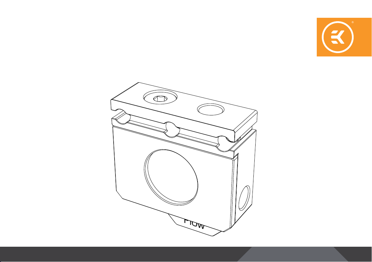
EKQuantum
Scalar Flow Indicator Bottom-Top D-RGB
1st Revision, July 20, 2020
INSTALLATION MANUAL

This product is intended for installation by expert users only. Please
consult with a qualified technician since improper installation
may result in damage to the equipment. EK assumes no liability
whatsoever, expressed or implied, for the use of these products,
nor their installation. The following instructions are subject to
change without notice. Please visit our website at www.ekwb.com
for updates.
Before you s tart using this prod uct, please follow t hese basic guidelines:
Carefully read the manual before beginning with the
installation process.
EK Fittings require only a small amount of force to screw
them firmly in place since the liquid seal is ensured with the
rubber O-ring gaskets.
The use of quality market-proven corrosion-inhibiting
coolants is always strongly recommended for any liquid
cooling system.
Do not use pure distilled water as a cooling liquid! For best
results, EK recommends the use of EK-CryoFuel Coolants.
TABLE OF CONTENTS
INSTALLING THE EK-QUANTUM SCALAR FLOW INDICATOR TOP-BOTTOM D-RGB 4
CONNECTING THE D-RGB LED STRIP 7
SUPPORT AND SERVICE 8
SOCIAL MEDIA 8
- 3 -

INSTALLING THE EK-QUANTUM SCALAR FLOW INDICATOR BOTTOM-TOP D-RGB
STEP 1
Carefully d etach the terminal cover toge ther with LEDs from the GPU
terminal. The latest EK water blocks come with no screws – all you
have to do is pull the cover away from the terminal. With the older
water block series, you may have to unscrew two screws (M4x8) to
remove the cover.
The cover can hang from the LEDs cable during installation, but
be careful not to pull on it.
Terminal Cover
STEP 1
STEP 2
Remove your GPU water block’s terminal. Unscrew the three screws
and remove the terminal from the GPU water block.
STEP 2
- 4 -

O-Rings
STEP 3
STEP 3
Insert the two enclosed O-rings into the appropriate grooves on the
backside of the Flow Indicator.
STEP 4
Use the three enclosed screws to attach the Flow Indicator (together
with O-rings) to the water block. Be careful not to use excessive force
when tightening the screws (ideal screwing torque is 0.5-0.7 Nm).
Also, make sure the O-rings are well placed inside the grooves,
so you won’t pinch them when screwing the Flow Indicator to the
water block.
STEP 4
- 5 -

STEP 5
STEP 5
Reattach the terminal cover to the Flow Indicator. Be careful not to
pinch the cable.
EK-Plug G1/4
Tubing
Flow Direction
EK-Fitting
Outlet
Flow Direction
Inlet
STEP 6
STEP 6
In order to complete the loop, all ports should be used as marked in
the picture. Make sure to use the correct inlet and outlet ports. EK
recommends EK Classic and EK Torque series fittings.
Make sure an EK plug is used, as shown in the picture.
EK-Fitting
- 6 -

CONNECTING THE D-RGB LED STRIP
D-RGB Header
RGB Header
Connect the 3-pin D-RGB LED connector from your Flow Indicator
to the D-RGB header on your motherboard or controller. The lights
will work if the pin layout on the header is as follows: +5V, Data,
Empty, Ground.
Incorrect installation or choosing the incorrect header may
result in damage to the LED Strip or the header itself.
- 7 -

SUPPORT AND SERVICE
In case you need assistance, please contact:
http://support.ekwb.com/
EKWB d.o.o.
Pod lipami 18
1218 Komenda
Slovenia - EU
SOCIAL MEDIA
EKWaterBlocks
@EKWaterBlocks
ekwaterblocks
EKWBofficial
ekwaterblocks
 Loading...