

EKQuantum
Reflection Fractal ATX D5 PWM D-RGB – Plexi
DISTRIBUTION PLATE
USER GUIDE

Before you start using this produc t please follow these basic guidelines:
Please carefully read the manual before beginning with the
installation process!
The EK Fittings require only a small amount of force to screw
them firmly in place since the liquid seal is ensured by the
rubber O-ring gaskets.
The use of corrosion inhibiting coo lants is always reco mmended
for any liquid cooling system. EKWB recommends any of the
EKCryofuel for worry-free usage.

TABLE OF CONTENT
PREPARING THE DEFINE R6/VECTOR RS 4
INSTALLING THE DISTRIBUTION PLATE IN THE DEFINE R6/VECTOR RS 6
PREPARING THE DEFINE S2/MESHIFY S2 7
INSTALLING THE DISTRIBUTION PLATE IN THE DEFINE S2/MESHIFY S2 8
PREPARING THE DEFINE 7/7 XL 9
INSTALLING THE DISTRIBUTION PLATE IN THE DEFINE 7/7 XL 9
RECOMMENDED DISTRIBUTION PLATE CONFIGURATIONS 10
CONFIGURATION WITH ONLY TOP RADIATOR 10
CONFIGURATION WITH BOTH RADIATORS 11
CONNECTING THE D-RGB LED STRIP 12
CONNECTING THE PUMP 13
TESTING THE LOOP 13
SUPPORT AND SERVICE 14
SOCIAL MEDIA 14
- 3 -
PREPARING THE DEFINE R6/VECTOR RS
Before installing the distribution plate, carefully read
the PC case manual.
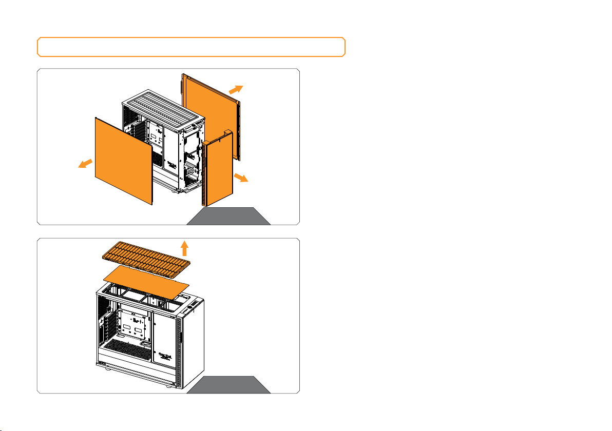
STEP 1
Remove the both side panels and the front panel from the case.
STEP 1
STEP 2
Remove the top filter frame and follow the process in the Fractal
Design R6 case manual to remove all drive mounts and re-position
the drive cover to the back of the case.
STEP 2
- 4 -
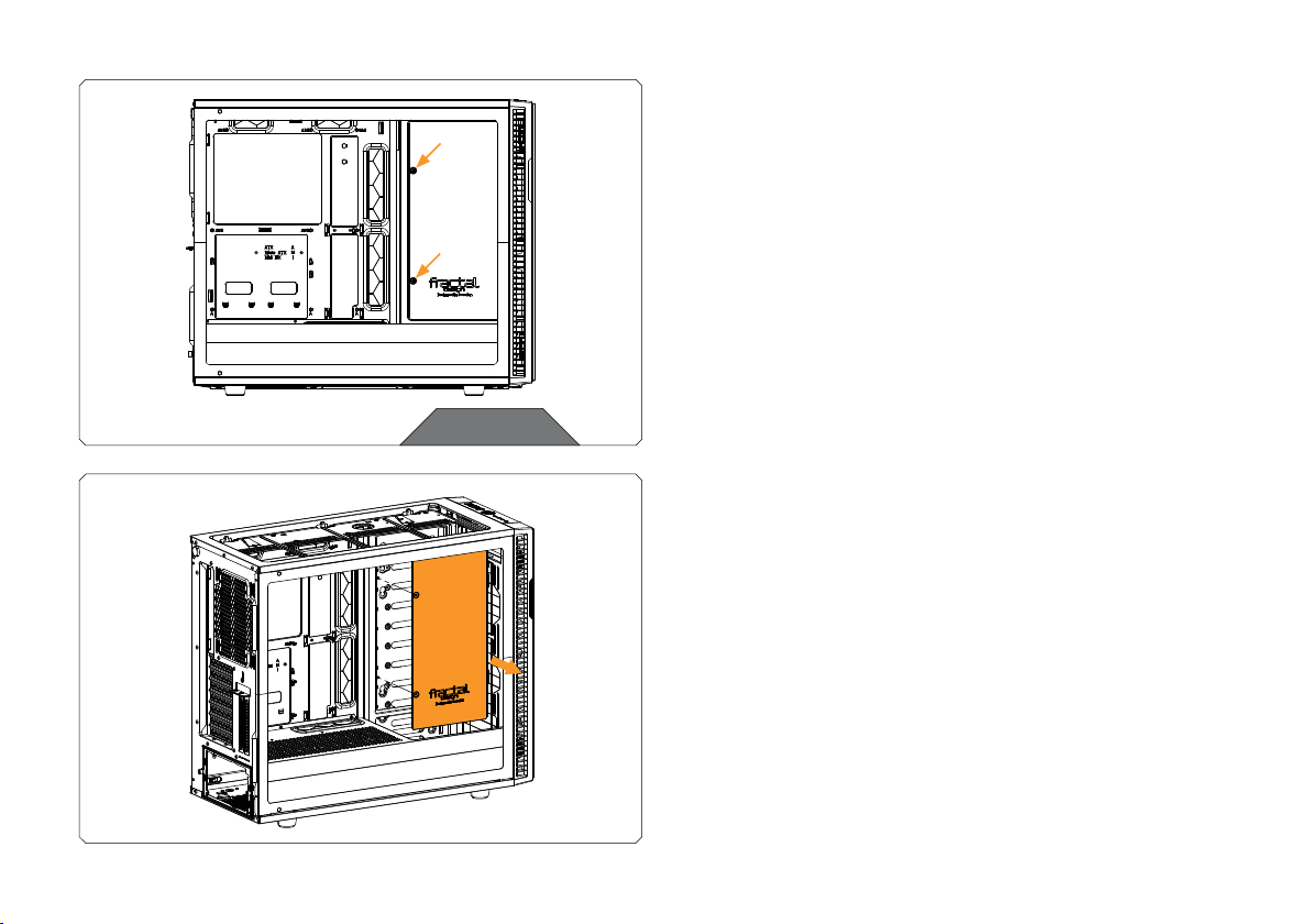
STEP 3
STEP 3
Unscrew two (2) encircled screws and use the marked holes for
distribution plate mounting screws.
You can also remove the drive cover in order to secure the
distribution plate with additional mounting screws if required.
- 5 -

INSTALLING THE DISTRIBUTION PLATE IN THE DEFINE R6/VECTOR RS
STEP 1
Carefully place the EK-Quantum Reflection Fractal ATX D5 PWM
D-RGB – Plexi distribution plate into the PC case. Make sure that
mounting holes are aligned.
STEP 1
STEP 2
Secure the EK-Quantum Reflection Fractal ATX D5 PWM D-RGB –
Plexi distribution plate with two M3 x 10 7984DIN screws and steel
washers.
Steel Washer
M3 X 10 DIN7984
STEP 2
- 6 -

PREPARING THE DEFINE S2/MESHIFY S2
Before installing the distribution plate, carefully read
the PC case manual.
STEP 1
Remove the both side panels from the case.
STEP 1
STEP 2
Remove the hard drive cage. It can be reused, after installing
EK-Quantum Reflection Fractal ATX D5 PWM D-RGB – Plexi
distribution plate.
STEP 2
- 7 -

INSTALLING THE DISTRIBUTION PLATE IN THE DEFINE S2/MESHIFY S2
STEP 1
Carefully place the EK-Quantum Reflection Fractal ATX D5 PWM
D-RGB – Plexi distribution plate into the PC case. Make sure that
mounting holes are aligned.
STEP 1
STEP 2
Secure the EK-Quantum Reflection Fractal ATX D5 PWM D-RGB –
Plexi distribution plate with enclosed M3 X 10 7984DIN mounting
screws and steel washers.
Steel Washer
M3 X 10 7984DIN
STEP 2
- 8 -

PREPARING THE DEFINE 7/7 XL
First take off the both side panels from the case.
Factory provided fans, drive cover and drive cages also need to be
removed in order to install the EK-Quantum Reflection Fractal ATX
D5 PWM D-RGB – Plexi distribution plate.
STEP 1
INSTALLING THE DISTRIBUTION PLATE IN THE DEFINE 7/7 XL
STEP 1
Carefully place the EK-Quantum Reflection Fractal ATX D5 PWM
M3 X 10
DIN7984
Screw
Steel
Washer
D-RGB – Plexi distribution plate into the PC case. Make sure that
mounting holes are aligned.
STEP 2
Secure the EK-Quantum Reflection Frac tal ATX D5 PWM D-RGB – Plexi
distribution plate with M3 x 10 7984DIN screws and steel washers.
STEP 1&2
- 9 -

RECOMMENDED DISTRIBUTION PLATE CONFIGURATIONS
CONFIGURATION WITH ONLY TOP RADIATOR
CPU OUTLET
CPU INLET
GPU INLET
(One must be used)
TOP RADIATOR
INLET
TOP RADIATOR
OUTLET
GPU OUTLET
(One must be used)
FILL
DRAIN
All remaining and unused por ts should be closed using the
supplied plugs and an EK-Loop Multi Allen Key (6mm, 8mm, 9mm).
- 10 -

FRONT RADIATOR
INLET
FRONT RADIATOR
OUTLET
CONFIGURATION WITH BOTH RADIATORS
All remaining and unused por ts should be closed using the
supplied plugs and an EK-Loop Multi Allen Key (6mm, 8mm, 9mm).
CPU OUTLET
CPU INLET
GPU INLET
(One must be used)
TOP RADIATOR
INLET
TOP RADIATOR
OUTLET
GPU OUTLET
(One must be used)
FILL
DRAIN
- 11 -

CONNECTING THE D-RGB LED STRIP
D-RGB Connector
Plug the 3-pin connector of the distribution plate D-RGB LED light to
the D-RGB HEADER on the motherboard. The LED will work if the pin
layout on the header is as follows: +5V, Digital, Empty, Ground.
Please ensure that the arrow indicated on the connector is
plugged into t he +5V line as indicated on yo ur motherboard.
If you put LED Diode to the 12V RGB HEADER you can
damage the LEDs.
Connector is the same on D-RGB and RGB versions,
but D-RGB version has 3 cables from connector to PCB;
RGB version has 4 cables. If you connect D-RGB led to
ordinary RGB header you can damage your motherboard
or LED strip.
- 12 -

CONNECTING THE PUMP
4-pin molex
connector
4-pin PWM fan
connector
TESTING THE LOOP
To make sure the installation of EK components was successful, we
recommend you perform a leak test for 24 hours.
When your loop is complete and filled with coolant, connect the
pump to a PSU outside of your system. Do not connect power to
any of the other components. Turn on the PSU and let the pump
run continuously. It is normal for the coolant level to drop during this
process as air collects in the distribution plate.
The EK-D5 PWM pump has two connectors.
1. 4-pin Molex: It must be connected directly to your PSU at all
times as it is used to power the pump.
2. 4-pin PWM fan: It can be connected to your motherboard’s
CPU_ Fan or designated water pump header. It can also be
connected to a controller. This cable is used to control and report
the rotational speed of the pump. If it’s not connected, the pump
will run at maximum speed (100% PWM).
Inspect all parts of the loop, and in the eventuality that coolant leaks,
fix the issue and repeat the testing process. Ensure that all hardware is
dry before the system is powered on in order to prevent any damage.
- 13 -

SUPPORT AND SERVICE
For assistance please contact:
http://support.ekwb.com/
EKWB d.o.o.
Pod lipami 18
1218 Komenda
Slovenia - EU
SOCIAL MEDIA
EKWaterBlocks
@EKWaterBlocks
ekwaterblocks
EKWBofficial
ekwaterblocks
 Loading...