

Eizo SCD 19102, SMD 19102 Instruction Manual
display
SOLUTIONS
SOLUTIONS
Instruction Manual • 05/2008
High End 19” Color and Gray Scale Flat Panel Display
SCD 19102
SMD 19102

Introduction
1
Safety notes
2
Description
3
Application planning
4
Assembly
5
Connecting
6
Commissioning
7
Operation
8
Service and maintenance
9
Troubleshooting
10
Technical data
11
Dimension drawings
12
Accessories
13
Appendix
A
List of
abbreviations/acronyms
B
LC displays for medical applications
High-End 19" Color and
Gray Scale Flat Panel Display
SCD 19102 / SMD 19102
Instruction Manual
05/2008
A5E01588521A-002
Safety Guidelines
This manual contains notices you have to observe in order to ensure your personal safety, as well as to prevent
damage to property. The notices referring to your personal safety are highlighted in the manual by a safety alert
symbol, notices referring only to property damage have no safety alert symbol. These notices shown below are
graded according to the degree of danger.
DANGER
indicates that death or severe personal injury will result if proper precautions are not taken.
WARNING
indicates that death or severe personal injury may result if proper precautions are not taken.
CAUTION
with a safety alert symbol, indicates that minor personal injury can result if proper precautions are not taken.
CAUTION
without a safety alert symbol, indicates that property damage can result if proper precautions are not taken.
NOTICE
indicates that an unintended result or situation can occur if the corresponding information is not taken into
account.
If more than one degree of danger is present, the warning notice representing the highest degree of danger will
be used. A notice warning of injury to persons with a safety alert symbol may also include a warning relating to
property damage.
Qualified Personnel
The device/system may only be set up and used in conjunction with this documentation. Commissioning and
operation of a device/system may only be performed by qualified personnel. Within the context of the safety notes
in this documentation qualified persons are defined as persons who are authorized to commission, ground and
label devices, systems and circuits in accordance with established safety practices and standards.
Prescribed Usage
Note the following:
WARNING
This device may only be used for the applications described in the catalog or the technical description and only
in connection with devices or components from other manufacturers which have been approved or
recommended by Eizo. Correct, reliable operation of the product requires proper transport, storage, positioning
and assembly as well as careful operation and maintenance.
Trademarks
All names identified by ® are registered trademarks of the EIZO GmbH. The remaining trademarks in this
publication may be trademarks whose use by third parties for their own purposes could violate the rights of the
owner.
Disclaimer of Liability
We have reviewed the contents of this publication to ensure consistency with the hardware and software
described. Since variance cannot be precluded entirely, we cannot guarantee full consistency. However, the
information in this publication is reviewed regularly and any necessary corrections are included in subsequent
editions.
EIZO GmbH
Display Technologies
Siemensallee 84
76187 KARLSRUHE
GERMANY
A5E01588521A-002
Ⓟ 05/2008
Copyright © EIZO GmbH 2008.
Technical data subject to change

SCD 19102 / SMD 19102
Instruction Manual, 05/2008, A5E01588521A-002
5
Table of contents
1 Introduction................................................................................................................................................ 9
1.1 Contents of this document .............................................................................................................9
1.2 Further documentation...................................................................................................................9
1.3 Program for changing the display settings...................................................................................10
2 Safety notes............................................................................................................................................. 11
3 Description............................................................................................................................................... 15
3.1 Scope of delivery .........................................................................................................................15
3.2 Applications..................................................................................................................................15
3.3 Important features........................................................................................................................16
4 Application planning................................................................................................................................. 19
4.1 Installation site .............................................................................................................................19
5 Assembly................................................................................................................................................. 21
5.1 Mounting of unit ...........................................................................................................................21
6 Connecting .............................................................................................................................................. 23
6.1 General connection information...................................................................................................23
6.2 Connector location .......................................................................................................................24
6.3 Summary of signals and connections ..........................................................................................24
6.4 Connector panel...........................................................................................................................25
6.5 Connecting the signal cables.......................................................................................................26
6.6 DIP switches (for SMD 19102 only).............................................................................................27
6.7 Connecting the line cord ..............................................................................................................28
6.8 Installing/removing the display stand and cable for the SCD 19102 ...........................................29
6.9 Serial interface .............................................................................................................................32
7 Commissioning ........................................................................................................................................ 35
7.1 Switching on the display ..............................................................................................................35
7.2 Operator controls .........................................................................................................................35
7.3 Description of OSD menu ....................................
........................................................................37
7.3.1 OSD overview ..............................................................................................................................37
7.3.2 Menu functions.............................................................................................................................38
7.3.3 Exit OSD ......................................................................................................................................50
7.3.4 Service level 2 functions ..............................................................................................................51
7.3.5 Lock/unlock OSD menu ...............................................................................................................56

Table of contents
SCD 19102 / SMD 19102
6 Instruction Manual, 05/2008, A5E01588521A-002
7.4 Make settings .............................................................................................................................. 56
7.4.1 Screen saver ............................................................................................................................... 57
7.4.2 Adjusting the image geometry .................................................................................................... 57
7.4.3 Adjusting the brightness and contrast......................................................................................... 57
7.4.4 Adaptation of display – video source / graphics card.................................................................. 58
7.4.5 Display adjustment - LUT............................................................................................................ 60
7.4.6 Display adjustment - Force mode ............................................................................................... 61
7.4.6.1 Introduction ................................................................................................................................. 61
7.4.6.2 Foreword (a number of useful points to facilitate understanding of timing and the various
types of timing)............................................................................................................................ 62
7.4.6.3 Blind mode .................................................................................................................................. 65
7.4.6.4 Live mode.................................................................................................................................... 66
8 Operation................................................................................................................................................. 71
8.1 Note for users.............................................................................................................................. 71
8.2 Switching on the display.............................................................................................................. 71
9 Service and maintenance ........................................................................................................................ 73
9.1 Cleaning ...................................................................................................................................... 73
10 Troubleshooting....................................................................................................................................... 75
11 Technical data ......................................................................................................................................... 77
11.1 Graphic display ........................................................................................................................... 77
11.2 Voltage supply............................................................................................................................. 78
11.3 Electronics................................................................................................................................... 78
11.4 Inputs/Outputs............................................................................................................................. 79
11.5 Control and connection elements ............................................................................................... 80
11.6 Mechanical design ...................................................................................................................... 80
11.7 Climatic conditions ...................................................................................................................... 81
11.8 Mechanical requirements ............................................................................................................ 81
11.9 Safety specifications ....................................................................................................
............... 82
11.10 Electromagnetic compatibility ..................................................................................................... 82
12 Dimension drawings ................................................................................................................................ 83
12.1 SCD / SMD 19102 C/CP (without stand) .................................................................................... 83
12.1.1 Front view.................................................................................................................................... 83
12.1.2 View from left .............................................................................................................................. 84
12.1.3 Rear view .................................................................................................................................... 85
12.1.4 View from above ......................................................................................................................... 85
12.2 SCD / SMD 19102 D (with stand) ............................................................................................... 86
12.2.1 Front view.................................................................................................................................... 86
12.2.2 View from left .............................................................................................................................. 87
12.2.3 View from above ......................................................................................................................... 88
13 Accessories ............................................................................................................................................. 89
13.1 Display stands ............................................................................................................................. 89
13.2 DVI transmission path and cable ................................................................................................ 90
13.3 Calibration tools .......................................................................................................................... 91

Table of contents
SCD 19102 / SMD 19102
Instruction Manual, 05/2008, A5E01588521A-002
7
13.4 Graphics cards .............................................................................................................................91
A Appendix.................................................................................................................................................. 93
A.1 Warranty.......................................................................................................................................93
A.2 Repairs.........................................................................................................................................93
A.3 Environmental protection .............................................................................................................93
A.4 Accessory devices .......................................................................................................................93
A.5 Contact.........................................................................................................................................93
A.6 China RoHS (Restriction of Hazardous Substances) ..................................................................94
A.7 Disposal of materials containing mercury ....................................................................................96
B List of abbreviations/acronyms ................................................................................................................ 99
Index...................................................................................................................................................... 101

Table of contents
SCD 19102 / SMD 19102
8 Instruction Manual, 05/2008, A5E01588521A-002

SCD 19102 / SMD 19102
Instruction Manual, 05/2008, A5E01588521A-002
9
Introduction
1
1.1 Contents of this document
This document explains the functionality and the approved application of the:
● SCD 19102 high-end color flat panel display
● SMD 19102 high-end gray scale flat panel display
To ensure clarity, it does not contain all detailed information on this product.
The contents of this document are neither part of a previous or existing agreement,
commitment or legal relationship, nor does it modify such.
The displays are available in color and monochrome variants:
Color flat panel display
● SCD 19102 C, version without protective front pane, without multi-functional stand
● SCD 19102 CP, version with protective front pane, IPx2 at front
● SCD 19102 D, version without protective front pane, with multi-functional stand
Gray scale flat panel display
● SMD 19102 C, version without protective front pane, without multi-functional stand
● SMD 19102 CP, version with protective front pane, IPx2 at front
● SMD 19102 D, version without protective front pane, with multi-functional stand
1.2 Further documentation
More information
These instructions are available on the supplied CD-ROM and on the Internet page of
EIZO GmbH Display Technologies: http://www.eizo.eu
SMfit® Total Care
Brief instructions for the software "SMfit® Total Care". The context-sensitive help is
integrated in the software.

Introduction
1.3 Program for changing the display settings
SCD 19102 / SMD 19102
10 Instruction Manual, 05/2008, A5E01588521A-002
1.3 Program for changing the display settings
SMfit® Total Care
The SMfit® Total Care program is a web-based application and is included in the software
and documentation CD shipped with each display. The software is also available as a free
download on the EIZO Display Technologies website.
The SMfit® Total Care software also has extensive calibration functions. To use these, you
will need a photometer and an activation code. The activation code can be purchased from
the EIZO GmbH.
Additional information may be contained in a Readme.txt file on the installation CD.
SMfit® Site Manager
SMfit® Site Manager is a web-based application. It is fully compatible with
SMfit® Total Care.
SMfit® Site Manager permits remote access to displays accessible via the network, allowing
centralized control from a single computer.
All data are saved in a central customer database and can be called up over the Internet and
Intranet.
Additional information about this software package is available on the EIZO Display
Technologies website.
See also
Internet (http://www.eizo.eu)
SCD 19102 / SMD 19102
Instruction Manual, 05/2008, A5E01588521A-002
11
Safety notes
2
Guarantee perfect operation - even in the medical sector
Please note that LC displays such as the SCD / SMD 19102 do not exhibit a zero error rate
and that the image parameters can change over time (e.g. color density or distortion/fading
of colors). Please ensure that all necessary steps are taken to avoid violations or incorrect
diagnoses. Regular maintenance and calibration are recommended.
Perfect, safe and reliable operation of the display requires that it has been professionally
transported, stored, mounted and installed as well as carefully operated and maintained. The
unit must only be used for applications for which displays are normally used. The technical
specifications of the product must be observed.
In the interests of safety, the following precautions must be observed:
DANGER
There is a danger to life if warnings are not obeyed. Severe personal injury or damage to
property may occur.
Do not open the unit yourself
Certain components inside the units operate at high-voltage, i.e. touching these
components represents a danger to life!
Only use a power cord in perfect condition
A damaged power cord may result in a fire or electric shock. When disconnecting the power
cord, always do so by holding the plug.
Do not insert any objects into the housing
Objects inserted into the housing may result in damage to the unit or personal injury.
Do not place any objects on top of the units
Penetrating liquids may result in a fire or electric shock.
Connecting
There must be no contact to a patient when handling the connection cables.
If the SCD / SMD 19102 is mounted on a stand:
Adjust the display height carefully, otherwise danger of injury
When adjusting the height of the display, make sure that you do not trap your fingers or any
other objects.
Safety notes
SCD 19102 / SMD 19102
12 Instruction Manual, 05/2008, A5E01588521A-002
CAUTION
Incorrect installation may result in extensive damage to property.
Installation must be carried out by specialists:
1. When installing your medical electrical system with our products in an environment with
patients, please observe the safety requirements of EN 60 601-1-1 (IEC 601-1-1)
"Specifications for the safety of medical electrical systems" in order to prevent injury to
patients and users of your systems.
2. Use appropriate measures to ensure that the leakage currents in particular remain
below the necessary limits. Appropriate measures are:
– Separators for signal input or signal output unit
– Use of a safety isolating transformer
– Use of the additional protective conductor connection
3. Only use signal cables and interface cables specified by the system manufacturer for
the installation.
4. Use power supply cables with PE contact. Only insert into sockets with PE contact.
5. For certain applications, the video earth can be connected separately to the protective
earth via the additional PE connection in the plug panel (observe IEC 601-1-1 ).
6. Close the plug panel using the provided cover, and lock with the screw.
7. Notes on installation:
The stability of the display must be ensured following mounting of the stand/holder. The
insertion depth of the mounting screws into the display must be between 7 and 9 mm.
8. Note for users:
The terminal panel closed by the cover must not be opened by the user.
9. Servicing information:
If housing components have to be removed for servicing, this must not be carried out in
the presence of patients, users, or other persons not involved with servicing.
10. For installations in the USA and Canada:
Molded power supply plugs must comply with the requirements for "hospital grade
attachments" CSA Std. C22.2 No. 21 and UL 498.
CAUTION
Failure to observe the warnings may result in substantial damage to property.
Do not subject device to excessive shocks
Take care when transporting! Use the original packaging! The panel in particular should be
protected against shocks.
Due to mechanical pressure or electrostatic discharge, touching the surface of the Flat
Panel Display may cause momentary distortion of the display.
CAUTION
Subsequent mounting of a stand
The SCD / SMD 19102 C and SCD / SMD 19102 CP displays are delivered without a
stand. To ensure that the complete system (display and stand) complies with the EN 60601
standard, a subsequently mounted stand must also comply with the EN 60601 standard.

Safety notes
SCD 19102 / SMD 19102
Instruction Manual, 05/2008, A5E01588521A-002
13
See also
Installation site (Page 19)
Mounting of unit (Page 21)
General connection information (Page 23)
Connecting the signal cables (Page 26)
Connecting the line cord (Page 28)
Serial interface (Page 32)
Safety specifications (Page 82)
Cleaning (Page 73)

Safety notes
SCD 19102 / SMD 19102
14 Instruction Manual, 05/2008, A5E01588521A-002

SCD 19102 / SMD 19102
Instruction Manual, 05/2008, A5E01588521A-002
15
Description
3
3.1 Scope of delivery
Note
It is recommendable to keep the packaging material for subsequent transport of the display.
All SCD / SMD 19102 displays are delivered with the following components:
● CD with user manual and SMfit® Total Care
● European power cord
● US power cord
● Chinese power cord
● DVI-D video cable
3.2 Applications
The high-end 19" (48 cm) color and gray scale flat panel displays:
SCD 19102 C Landscape,
ceiling suspension
SCD 19102 CP Landscape,
ceiling suspension, with protective front
pane, IPx2 at front
SCD 19102 D Landscape,
desktop, with multifunctional stand
SMD 19102 C Landscape,
ceiling suspension
SMD 19102 CP Landscape,
ceiling suspension, with protective front
pane, IPx2 at front
SMD 19102 D Landscape,
desktop, with multifunctional stand
have been specially designed for medical diagnostics according to the safety standard
IEC 601. The displays comply with the safety standards UL 2601 and EN 60601-1.

Description
3.3 Important features
SCD 19102 / SMD 19102
16 Instruction Manual, 05/2008, A5E01588521A-002
3.3 Important features
The Flat Panel Display has the following features which permit a wide range of applications:
Compact design
Low weight and small dimensions with improved performance make the SCD / SMD 19102
high-end color flat panel displays preferable to conventional CRT monitors. Thanks to the
equally narrow frame on each edge, the display fits into any environment, and is ideally
suited to both desktop and ceiling suspension.
Perfect picture reproduction thanks to LCD technology
The use of LCD technology eliminates picture geometry distortions and color spots.
The high-end color and gray scale flat panel displays provide flicker-free pictures even at low
refresh rates (60 Hz). The SCD / SMD 19102 high-end color and gray scale
flat panel displays therefore meet even the highest ergonomic requirements.
Modification of gray scale setting
In medical applications (e.g. for X-rays, computer tomography and MRI scanners), where
pictures are usually displayed in shades of gray, the gray values can be adapted to the
user's eye: this display setting, which is referred to as calibration, is performed at the factory
and is therefore available on shipment (factory calibrated display). In addition, five different
settings (Look Up Table – LUT) are saved in the display. In order to switch to other LUTs,
please contact the service personnel, who will perform the setting via the on-screen display
(OSD – Service level 2) or the SMfit® Total Care (automatic calibration tool) software (also
Service level 2).
Screen resolution
The SCD / SMD 19102 high-end color flat panel displays are equipped with an active 19"
TFT display module which provides a very wide viewing angle. The display offers maximum
gray scale contrast (display function) across a very wide viewing angle (in-plane switching
(IPS) technology). The optimum picture resolution is 1280 x 1024 pixels. Video signals with
other resolutions, as are common in medical technology, are enlarged or reduced to fit the
screen size. Alternatively, they can be displayed in their original size (1:1).
RGB input (15-pin Sub-D/DVI/BNC)
SCD 19102
● The display is connected to the computer system using either the 15-pin Sub-D connector
or the DVI-I input socket.
SMD 19102
● The display is connected to the computer system using either the 15-pin Sub-D input
socket, the BNC sockets or the DVI input socket (digital only).
If necessary, the monitor display is adapted using an OSD menu.

Description
3.3 Important features
SCD 19102 / SMD 19102
Instruction Manual, 05/2008, A5E01588521A-002
17
Video inputs
The SCD / SMD 19102 displays feature two additional analog video inputs. The displays can
therefore be operated with analog standard video signals (PAL/NTSC). The RGB and video
inputs can be simultaneously connected to different signal sources.
Force mode
The force mode function is used to adapt the SCD / SMD 19102 displays to special timing
settings.
Protective glass
The SCD / SMD 19102 CP has anti-glare protective glass fitted over the top of the LCD
panel to protect the surface of the panel against bumps and scratches. The display is
protected at the front against moisture (IPx2 protection). The space between the protective
pane and the panel is sealed to prevent dust from entering, thus helping ensure the internal
surfaces remain clean.
Landscape and portrait modes
The display can be used in landscape and portrait modes. The image rotation for portrait
mode is made on the graphics card.
In portrait mode, the keypad is positioned at the top right and the OSD is not rotated (i.e. the
OSD inscription "Dynamic help for keypad function" is still positioned above the keys).

Description
3.3 Important features
SCD 19102 / SMD 19102
18 Instruction Manual, 05/2008, A5E01588521A-002

SCD 19102 / SMD 19102
Instruction Manual, 05/2008, A5E01588521A-002
19
Application planning
4
4.1 Installation site
Provide adequate ventilation
Ventilation slots are located on the rear of the housing.
The distance at the rear must be at least 10 cm from a wall or 15 cm from other units.
Observe the permissible ambient temperature range
The unit must not be operated outside the permissible ambient temperature range.
Desktop installation
If the SCD / SMD 19102 is mounted on a stand, it must be positioned on a hard, horizontal
surface.
Avoid reflections on the screen
The display has an anti-glare surface which is only effective with a clean, grease-free
screen.
The SCD / SMD 19102 CP display includes an optically coated protective glass pane, which
is well suited for use in a germ-free environment when cleaning agents are used.
If the screen surface is dirty, clean it using a suitable microfiber cloth.
Please note the additional cleaning instructions, see the section "Service and
Maintenance" (Page 73).
The display should be positioned so that reflections of lights, windows, furniture with shiny
surfaces or light-colored walls do not appear on the screen.
In order to reduce mirroring on the unit, only use non-dazzling reflector lights for the ceiling
lighting.
Change of environment
If the unit is brought into a warm environment from a cold one, condensation may form in the
unit. The unit should not be switched on until all the condensed water has evaporated,
including that inside the unit. This may take several hours, depending on the conditions.
See also
Cleaning (Page 73)

Application planning
4.1 Installation site
SCD 19102 / SMD 19102
20 Instruction Manual, 05/2008, A5E01588521A-002
SCD 19102 / SMD 19102
Instruction Manual, 05/2008, A5E01588521A-002
21
Assembly
5
5.1 Mounting of unit
Ceiling suspension
The display can be mounted flush with horizontally and vertically adjacent displays.
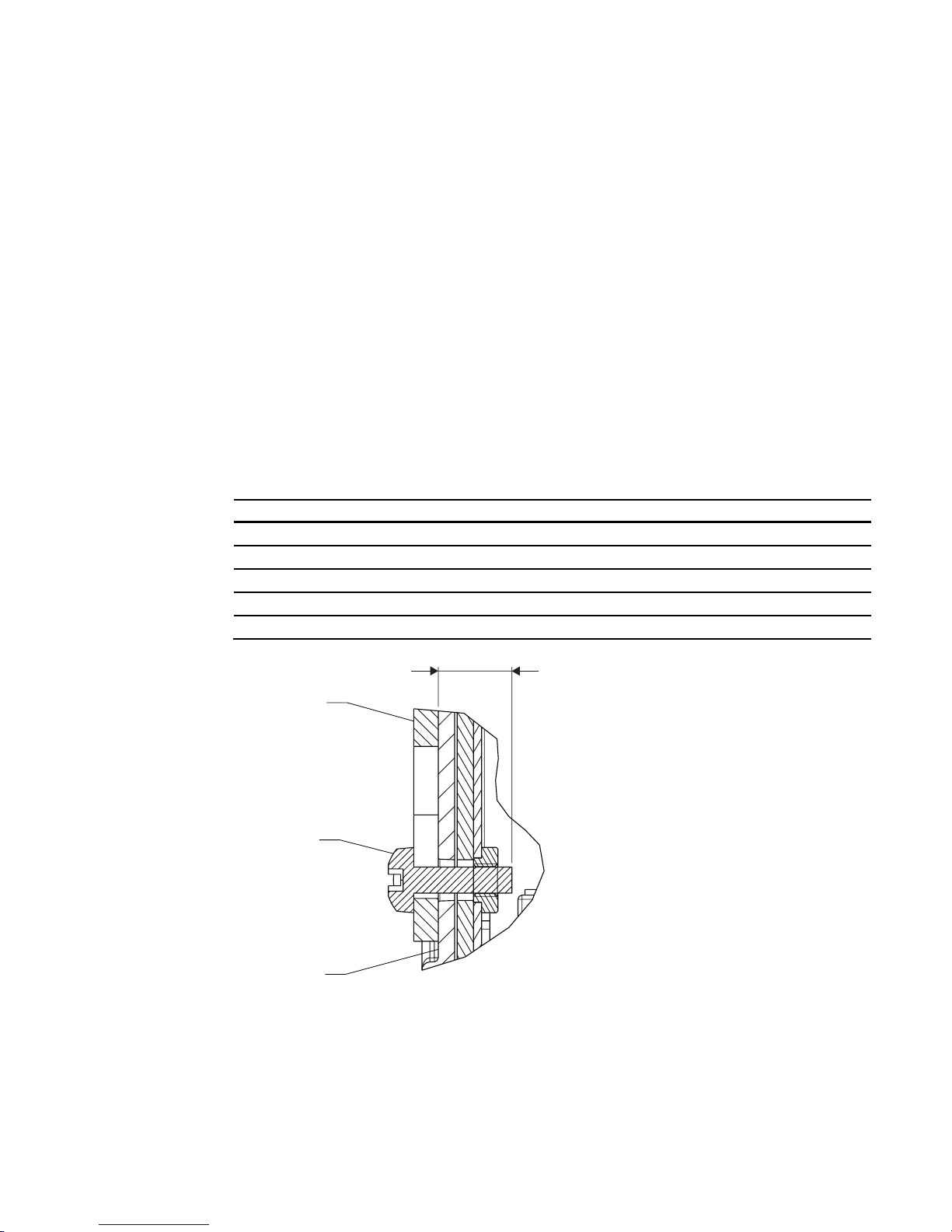
The following must be observed when mounting (100 mm hole spacing according to VESA
standard):
Information on the fastening screws
Number 4
Thread M4
Strength 8.8
Insertion depth 7 mm minimum / 9 mm maximum
Torque Max. 3 Nm
0RXQWLQJSDG
6FUHZ0
'LVSOD\KRXVLQJ
PP
Figure 5-1 Insertion depth of mounting screws
See also
Safety notes (Page 11)
Installing/removing the display stand and cable for the SCD 19102 (Page 29)

Assembly
5.1 Mounting of unit
SCD 19102 / SMD 19102
22 Instruction Manual, 05/2008, A5E01588521A-002
SCD 19102 / SMD 19102
Instruction Manual, 05/2008, A5E01588521A-002
23
Connecting
6
6.1 General connection information
CAUTION
All information and warnings related to this product must be observed to ensure dangerfree operation.
CAUTION
Information for end customers
All modifications to settings may only be carried out by trained servicing personnel,
otherwise the guarantee is canceled.
The display is designed for individual connection to a graphics card with a power supply of
110 or 240 V (TN-S system with PE conductor).
CAUTION
Observe shielding measures
Please observe all local EMC guidelines pertaining to shielding. Ignoring such requirements
could allow signals to interfere with the proper operation of the display.
To guarantee perfect image reproduction, the following instructions should be observed:
• Only shielded cables are permitted for all signal connections.
• Screw tight or lock all plug-in connections.
• Signal and power cables must not be routed through the same duct.
• The display must not share a power supply with motors or valves (interference peaks!).
See also
Safety notes (Page 11)
Electromagnetic compatibility (Page 82)

Connecting
6.2 Connector location
SCD 19102 / SMD 19102
24 Instruction Manual, 05/2008, A5E01588521A-002
6.2 Connector location
The connectors are located within the connection compartment under the cover on the rear
of the display. The power switch is not covered and is freely accessible.
6FUHZ
&RYHU
3RZHUVZLWFK
6HUYLFH
SLQPLQL',1VRFNHW
Figure 6-1 Rear view of SCD / SMD 19102
6.3 Summary of signals and connections
6&'60'
'LJLWDO
5*% 9LGHR
$QDORJ
&RPSRVLWH
[%1& SLQ0LQL',1
69LGHR'9,
['9,,
9*$
SLQVXE' '9,,6&'
$QDORJ5*%
[%1&60'
6R*+9
Connecting
6.4 Connector panel
SCD 19102 / SMD 19102
Instruction Manual, 05/2008, A5E01588521A-002
25
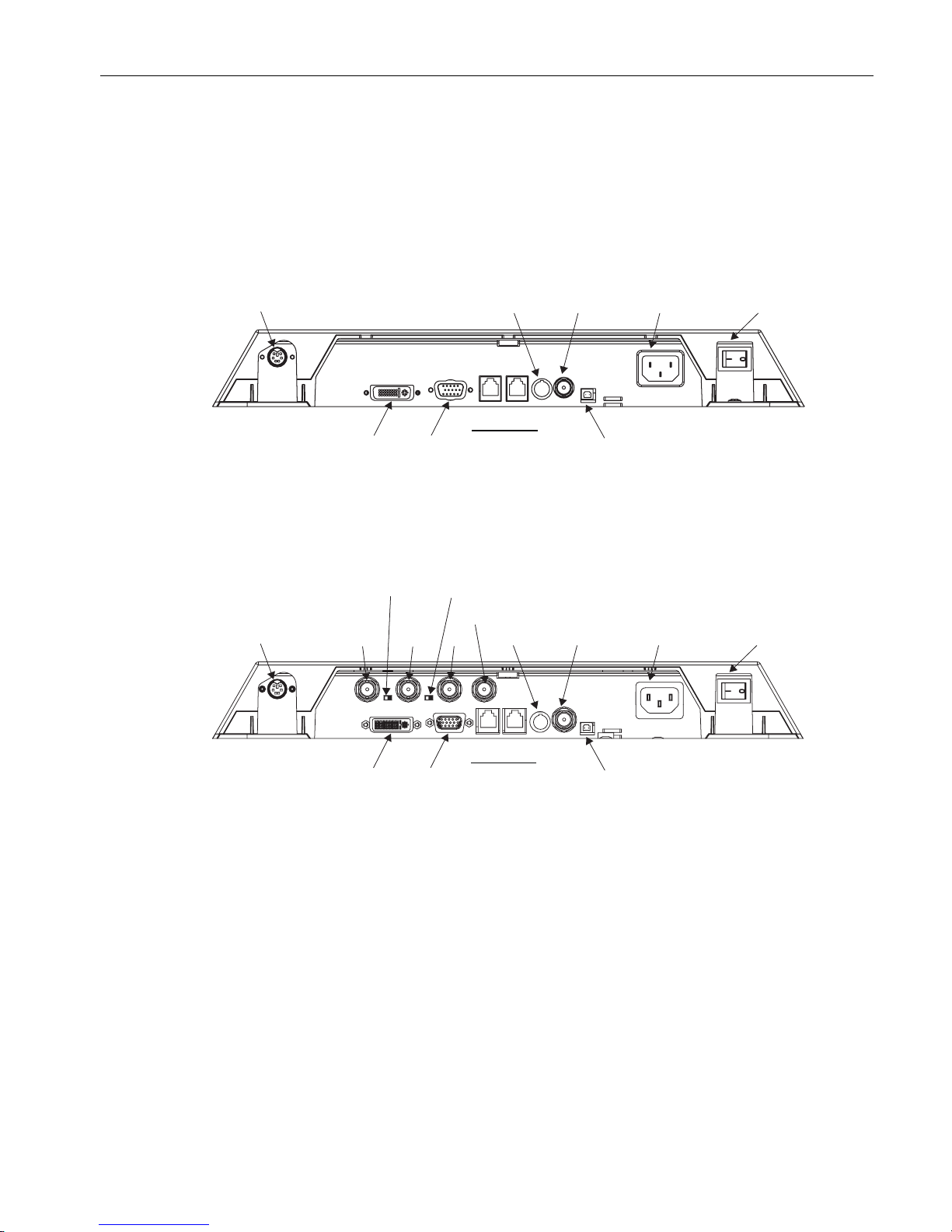
6.4 Connector panel
A connection panel for the signals and power supply is located at the rear of the flat panel
display.
SCD 19102
'9,
/LQHVXSSO\
FRQQHFWLRQ
3RZHUVZLWFK
6HUYLFHPHDVXULQJLQVWUXPHQWV
9*$
9
56
EXV
6HUYLFH
'RZQ8S
69LGHR &RPSRVLWH
Figure 6-2 Connection panel of the SCD 19102 high-end color flat panel display.
SMD 19102
6HUYLFH
PHDVXULQJ
LQVWUXPHQWV
/LQHVXSSO\
FRQQHFWLRQ
3RZHUVZLWFK69LGHR &RPSRVLWH
˖N˖VZLWFKORRSIRU+DQG9
'9,
9*$
9
56
EXV
6HUYLFH
'RZQ8S
6R** 9++9
6R**RXWSXW
Figure 6-3 Connection panel of the SMD 19102 high-end gray scale flat panel display
See also
Connecting the signal cables (Page 26)
Connecting the line cord (Page 28)
Serial interface (Page 32)
Connecting
6.5 Connecting the signal cables
SCD 19102 / SMD 19102
26 Instruction Manual, 05/2008, A5E01588521A-002
6.5 Connecting the signal cables
Note
• The video signals coming from a graphics card are referred to below as RGB signals, and
those coming from a camera, DVD player, video recorder etc. as video signals.
In the OSD menu, some of the menu displays are also appropriately identified by RGB or
video in the header.
• At least one signal source must be connected in order to activate the OSD.
• All signal inputs may be connected simultaneously.
• The Up and Down keys can be used to select which RGB or video source is to be
displayed when the OSD is not active. Selection is also possible in the OSD.
CAUTION
• When connecting to the BNC sockets, the three cables for the R, G and B signals must
be of equal length. Otherwise, color fringing, which appears similar to convergence
faults, will occur due to unequal propagation times.
• The levels of the incoming analog RGB signals must be equal.
• If the same RGB signal is connected to several displays via the BNC sockets using T-
connectors, the R, G, B and H DIP switches on the displays must be set to 10 kΩ.
These DIP switches must be set to 75 Ω on the last display in the sequence.
The signal connections are located at the rear of the flat panel display.
15-pin Sub-D socket
● Connect VGA cable with 15-contact Sub-D connector (male) for the analog input to the
15-contact Sub-D connector (female).
DVI socket
The DVI cable can be connected in two manners:
● With DVI digital signal or
● With DVI analog signal (SCD 19102 only)
BNC sockets (SoG / H / V)
● With a wire (R or G or B, with composite synchronization):
– Connecting wire for BNC connection "G".
● With three wires (R or G or B, with separate synchronization):
– Connecting wire for BNC connections "G", "H/H+V" and "V".
4-pin mini-DIN socket (video input)
● Connect video cable for the sync video input (Y/C signal) to the 4-pole mini-DIN socket.
Connecting
6.6 DIP switches (for SMD 19102 only)
SCD 19102 / SMD 19102
Instruction Manual, 05/2008, A5E01588521A-002
27
BNC socket (video input)
● Connect video cable for the composite input to the BNC socket.
See also
Connector panel (Page 25)
Safety notes (Page 11)
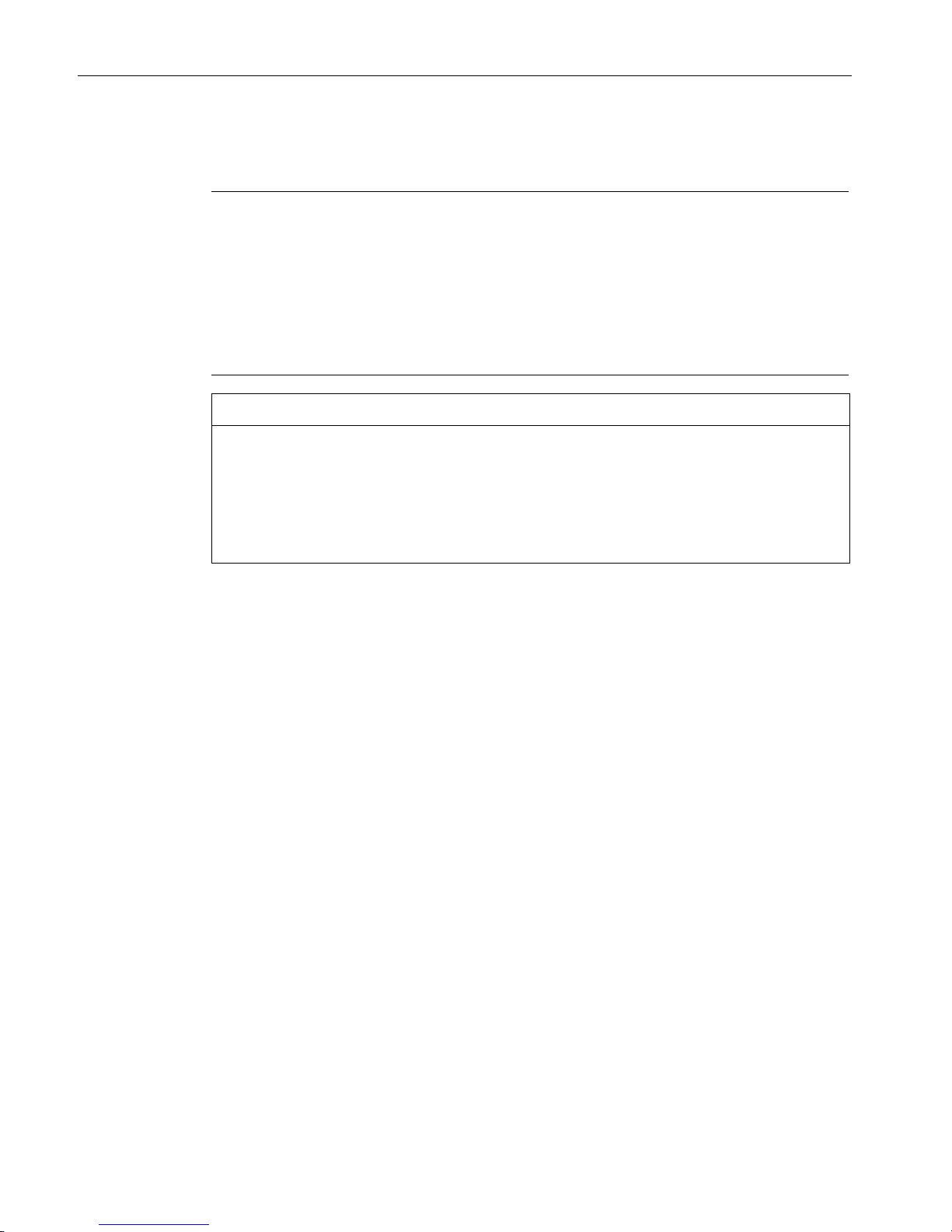
6.6 DIP switches (for SMD 19102 only)
The SMD 19102 has two DIP switches between the three BNC sockets.
These switches are used for changeover between high impedance (10 kΩ) and low
impedance (75 Ω) for the H and V synchronization inputs.
6: 6:
Figure 6-4 Position of the DIP switches
Delivery state
Switch Function Delivery state
SW1 Input resistance for H/H+V
signal
75 Ω
SW2 Input resistance for V signal 75 Ω

Connecting
6.7 Connecting the line cord
SCD 19102 / SMD 19102
28 Instruction Manual, 05/2008, A5E01588521A-002
6.7 Connecting the line cord
The power supply socket is on the rear of the flat panel display (only open using appropriate
tool!). The display power supply is connected using an appliance plug.
● Insert the appliance plug of the supplied power cord into the mains socket.
● The power cord can be secured using a cable grip.
3RZHUVXSSO\FRQQHFWLRQ
3RZHUVZLWFK
WARNING
• Only use the supplied power cord, or a cable with PE conductor and appliance plug
to DIN 49 547, IEC 320 (max. length 3 m). Furthermore, the cable must adhere to all
local safety regulations applicable to the specific country in which the display is used.
• Device fuses must only be replaced by the repair centers or servicing department.
• Note for North America: Molded power supply plugs must comply with the
requirements for hospitals with respect to CSA Std. C22.2 No. 21 and UL 498.
See also
Connector panel (Page 25)
Safety notes (Page 11)
Connecting
6.8 Installing/removing the display stand and cable for the SCD 19102
SCD 19102 / SMD 19102
Instruction Manual, 05/2008, A5E01588521A-002
29
6.8 Installing/removing the display stand and cable for the SCD 19102
CAUTION
Do not use screws of excessive length (Page 21)
Screws which are too long can damage mechanical and electronic components of the unit.
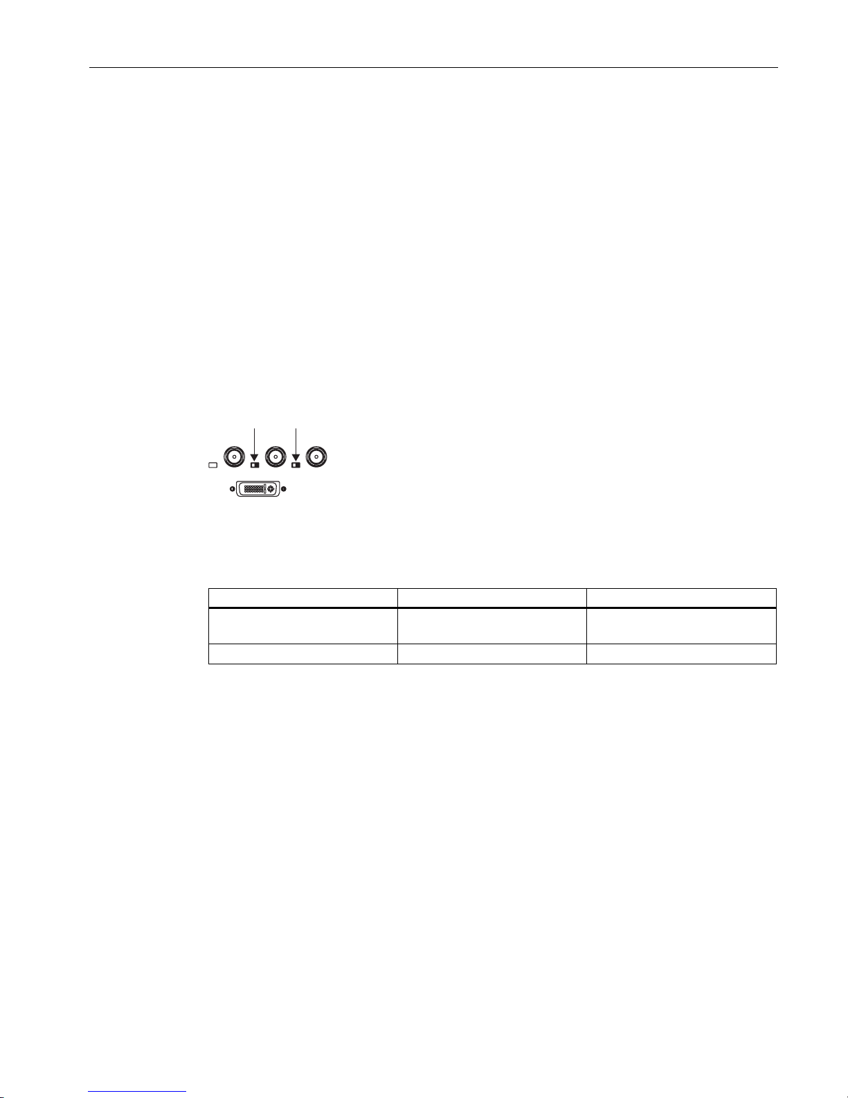
1. Attach the connecting cable before mounting the foot on the display.
2. Fit the screws on the mounting plate loosely.
Place the display with the loosely fitted screws on the display foot:
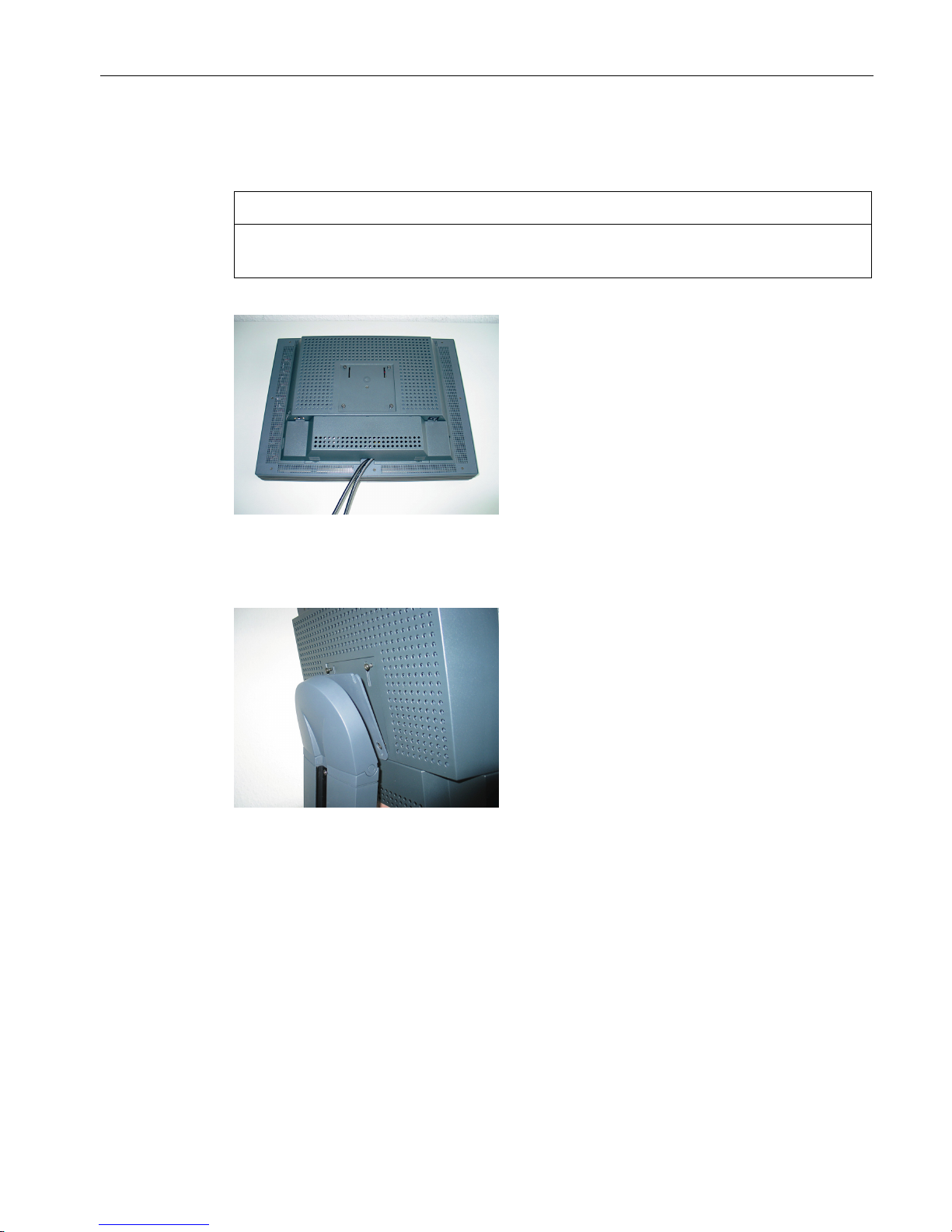
3. First insert two screws into the bottom two drilled holes of the display stand.
4. Then insert the remaining screws into the top two drilled holes.
5. Slowly lower the display.
Connecting
6.8 Installing/removing the display stand and cable for the SCD 19102
SCD 19102 / SMD 19102
30 Instruction Manual, 05/2008, A5E01588521A-002
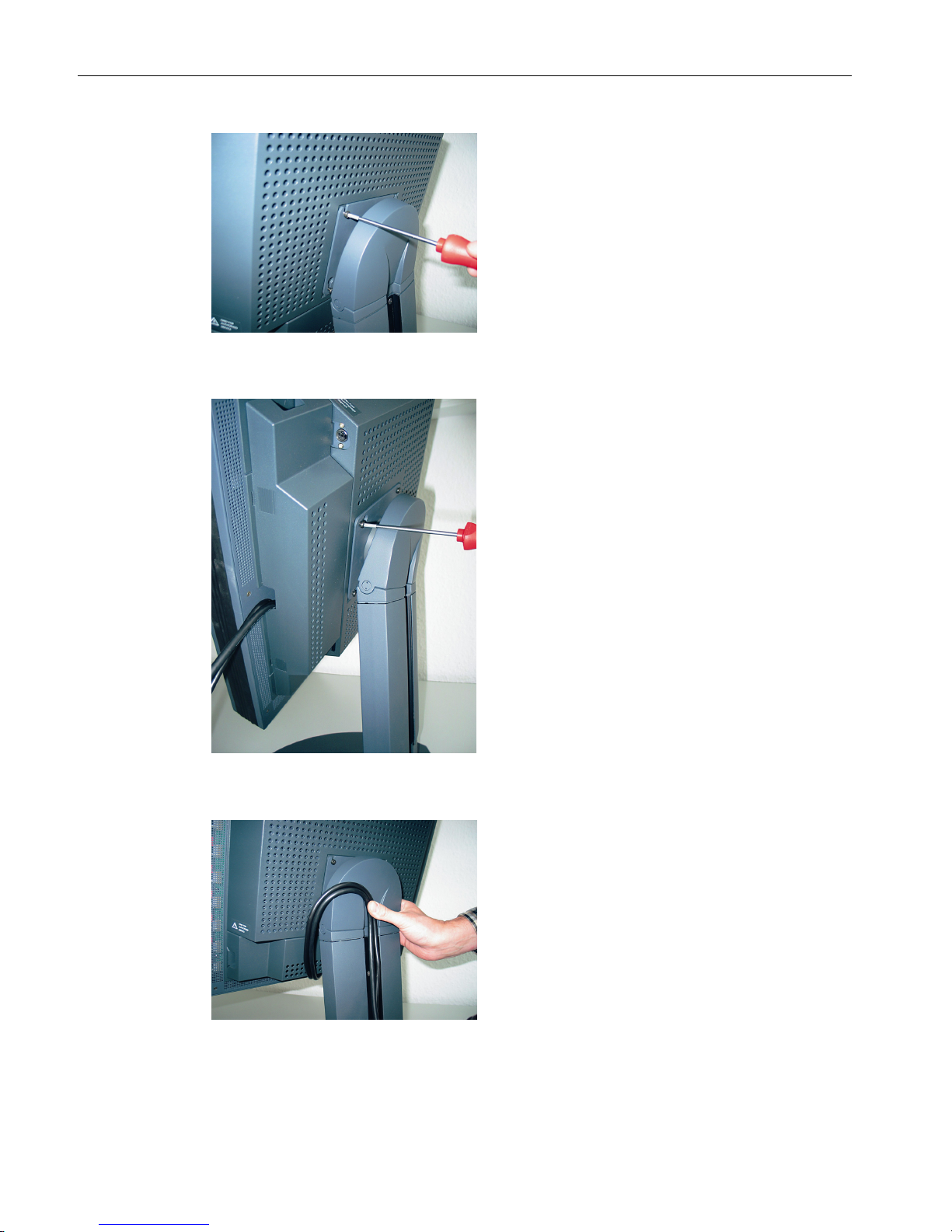
6. First tighten the top two screws.
7. Then rotate the display slightly, and tighten the bottom screws.
8. Lay the connecting cable in the cable duct.
 Loading...