

Page 1
Installation Manual
IP Decoding Box
Software Version 5.2
Important
Please read this “Installation Manual”, “Instruction Manual”, and
“Setup Manual” carefully to familiarize yourself with safe and eective
usage.
• For the latest product information including the “Installation Manual”,
refer to our web site :
www.eizoglobal.com
Page 2

Related Manuals
Setup Manual
Describes precautions and procedures for connecting network cameras and
for displaying camera images on the monitor. (Installation and initialization
guidance)
Installation Manual
(this manual)
Instruction Manual
*1 The Instruction Manual and Installation Manual for the latest software version used can be obtained from
our web site. Select “Manuals” from “Support”, enter “DX0211-IP” in the “Enter model name” box, and click
“Search”.
www.eizoglobal.com
Installation of Adobe
*1
*1
®
Describes network camera registration, function settings, and system settings.
(Detail settings guidance)
Describes operation of live image screen menus. (Operation guidance)
Acrobat® Reader® is required.
This product has been adjusted specically for use in the region to which it was originally shipped. If
operated outside this region, the product may not perform as stated in the specications.
No part of this manual may be reproduced, stored in a retrieval system, or transmitted, in any form or by
any means, electronic, mechanical, or otherwise, without the prior written permission of EIZO Corporation.
EIZO Corporation is under no obligation to hold any submitted material or information condential unless
prior arrangements are made pursuant to EIZO Corporation’s receipt of said information. Although every
eort has been made to ensure that this manual provides up-to-date information, please note that EIZO
monitor specications are subject to change without notice.
2
Page 3

CONTENTS
CONTENTS ............................................................. 3
Chapter 1 Product Overview ............................. 4
1-1. Features ......................................................... 4
1-2. System Conguration .................................. 5
1-3. Supported Network Cameras ...................... 6
Chapter 2 Before Conguration ........................ 7
2-1. Logging In to the System ............................. 7
Conguring from this product .......................... 7
●
Conguring from a web browser ..................... 9
●
2-2. Setting Screen ..............................................10
Basic Information ...........................................10
●
System Settings .............................................10
●
Live Image Screen Settings ...........................10
●
Chapter 3 System Settings .............................. 11
3-1. Performing Network Settings ..................... 11
3-2. Performing Communication Settings .......13
3-3. Setting the Current Date and Time ............15
3-4. Other System Settings ................................17
3-5. Initializing the System .................................18
3-6. Restarting the System .................................19
3-7. Updating Software ...................................... 20
3-8. Saving Settings Data .................................. 22
3-9. Loading System Settings Data .................. 23
3-10. Performing License Activation ................. 25
3-11. Setting Event Rules .................................... 26
3-12. Performing Certicate Settings ................ 28
3-13. Setting the Remote Control ID .................. 30
Setting the product ID ................................... 30
●
Setting the remote control ID .........................31
●
3-14. Checking Logs .............................................31
3-15. Saving Logs ................................................. 32
3-16. Performing Camera Connection
Conrmation ................................................ 33
Conrming Network Connection Status
3-17.
Chapter 4
4-1. Registering the Network Cameras ............ 35
4-2.
4-3. Auto Discovery of Network Cameras ....... 40
4-4. Deleting Network Cameras .........................41
4-5.
4-6.
4-7. Setting Network Camera Time .................. 45
4-8. Setting Quality of Transmission Video
Management of Network Cameras
Changing Network Camera Information
Exporting Network Camera Information
Importing Network Camera Information
Images .......................................................... 46
... 34
... 35
... 38
... 42
... 43
Chapter 5 Live Image Screen Settings ........... 49
5-1. Setting Display Positions of Camera
Video Images ............................................... 49
5-2. Setting Display Methods of Camera
Video Images ................................................51
5-3. Setting Custom Screen Layouts ............... 52
5-4. Setting the Display Methods of Live
Image Screens ............................................. 53
5-5. Setting Current Monitor Display Status ... 54
Chapter 6
6-1. Registering the User Account ................... 55
6-2. Changing the User Account ...................... 57
6-3. Deleting the User Account ......................... 58
6-4. Conguring Auto Login Settings .............. 59
6-5. Performing LDAP Settings ........................ 60
Management of the User Account
... 55
Chapter 7 Troubleshooting .............................. 62
7-1. Imaging Problems ....................................... 62
7-2. Setting Problems ........................................ 64
List of Functions ................................................. 65
Appendix .............................................................. 66
Trademark ............................................................... 66
License .................................................................... 66
CONTENTS
3
Page 4

Chapter 1 Product Overview
This product is a device that outputs video images from a maximum of 32 network cameras*1 to monitors
connected using HDMI cable.
This manual describes network camera settings, system settings, and product specications.
*1 A type of camera which converts images into network signals and transmits the signals.
1-1. Features
Communication with network cameras
●
• Possible to receive video images from a 4K camera (3840 × 2160 / 30 fps)
• Possible to display video signals from network cameras on a monitor
- Supports H.264, H.265, and MJPEG compression formats.
- A maximum of 48 network cameras can be registered.
- Allows a free layout of video images (1 Screen, 3 Screens, 4 Screens, 9 Screens, 16 Screens,
32 Screens, 8 Screens, and Custom Screen) from multiple network cameras.
- Supports Unicast and Multicast communication methods.
- Possible to switch the display position of camera video images while displaying video images.
Possible to output to a 4K monitor
●
• Supports 4K output (3840 × 2160 / 60 fps max.)
Supports multiple types of network cameras
●
• Compatible with ONVIF Prole S
• Supports camera control using network camera manufacturer specic protocols
(When connecting Panasonic or AXIS network cameras)
System management
●
• Possible to register network cameras or set the live image screen using a Web browser
• Possible to save and load settings data
Possible to save or load the setting data onto a computer.
Security
●
• Alert display
Possible to display an alert on the live image screen when communication with network cameras is lost.
Supports secure communication
●
Utilizes SSL and TLS, which are secure protocols. Communication between network cameras and
web pages is encrypted using SSL and HTTPS.
Purchase an Enterprise License to use LDAP authentication.
For details, contact your dealer or local EIZO representative.
Chapter 1 Product Overview
4
Page 5
Support
●
• A 2-year long-term warranty for 24-hour continuous use
Operation
●
• Operations can be performed by using a keyboard or mouse
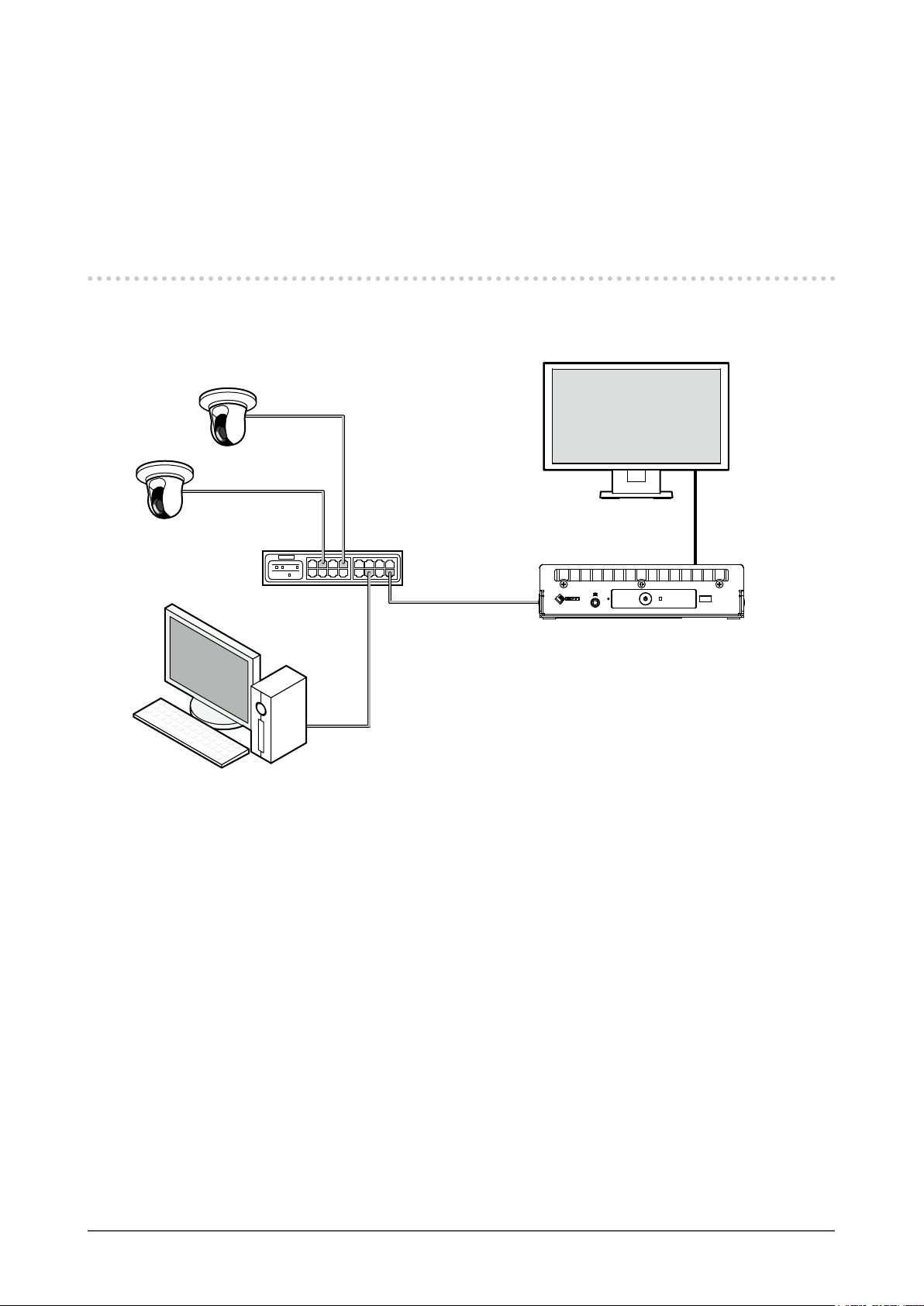
1-2. System Conguration
This system can communicate with network cameras, display video on the monitor that is connected to
this product, and operate the network cameras.
Monitor
Network cable
Network camera
Network cable
Network hub
*2
PC
*1 Up to 48 network cameras can be registered.
*2 Use a network hub that supports PoE+. If the hub does not support the PoE+ standard, network cameras and
DX0211-IP must be individually connected to the power supply.
*3 When setting the network cameras using a Web browser, use a computer on the same network as the DX0211-
I P.
*1
HDMI cable
*2
Network cable
DX 0 211 - I P
Network cable
Chapter 1 Product Overview
5
Page 6

1-3. Supported Network Cameras
This product supports ONVIF Prole S network cameras.
Attention
• Supported network cameras vary depending on the product's software version. Check the software version of the
product you are using, then check our website (www.eizoglobal.com) for details on supported network cameras.
For information on how to check the software version, refer to “2-2. Setting Screen” (page 10).
• For installing and setting the network cameras, refer to the network camera User’s Manual.
Note
• To verify the connection of a network camera, the image of the network camera can be accessed by specifying
the URI. For details, refer to “4-1. Registering the Network Cameras” (page 35).
Chapter 1 Product Overview
6
Page 7
Chapter 2 Before Conguration
System settings can be made from the screen (application screen) displayed on the monitor connected to
the product or from the web browser of a computer connected to the same network.
2-1. Logging In to the System
To congure this product, you need to log in to the system.
Login is allowed only when the level of the user accessing the product is “ADMIN”.
Log in to the system according to the following procedure.
Note
• The following user information is set by default.
- Username: “admin”
- Password: “admin”
- User Level: “ADMIN”
• For information on user settings, refer to “Chapter 6 Management of the User Account” (page 55).
• It is recommended that you log out after completing the setup, so as to prevent a third party from operating the
network camera or altering the settings.
• When the Auto Login settings are congured, it is possible to log in to the system without the username and
password.
For details, refer to “6-4. Conguring Auto Login Settings” (page 59).
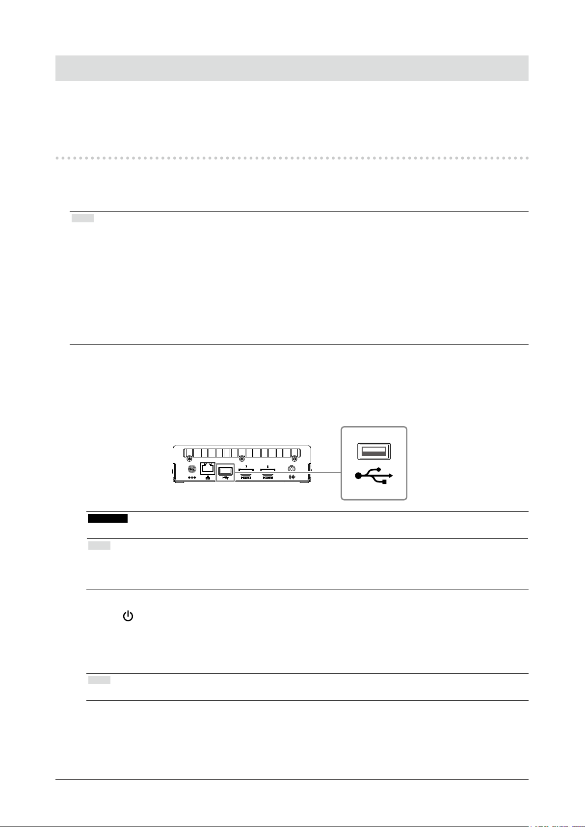
Conguring from this product
●
A USB mouse is required when operating from the application screen.
Connect a USB mouse to the USB downstream port of this product.
Attention
• Adjust the monitor in advance so that the HDMI input can be displayed.
Note
• When connected to a device that has the USB hub function, both the USB mouse and USB keyboard can be
used.
• For entering characters, refer to “Entering characters” (page 9).
Press on the front of this product.
1.
The power indicator lights up blue and the live image screen is displayed on the monitor connected to
this product.
(For information on the live image screen, refer to the “Instruction Manual”.)
Note
• The power supply is set to “On” by default.
Chapter 2 Before Conguration
7
Page 8

Select (Login) under “System”.
2.
The login screen is displayed.
Enter “Username : ” and “Password : ”.
3.
Select “Login”.
4.
The display returns to the live image screen.
Select (Settings).
5.
The setting screen is displayed.
Chapter 2 Before Conguration
8
Page 9
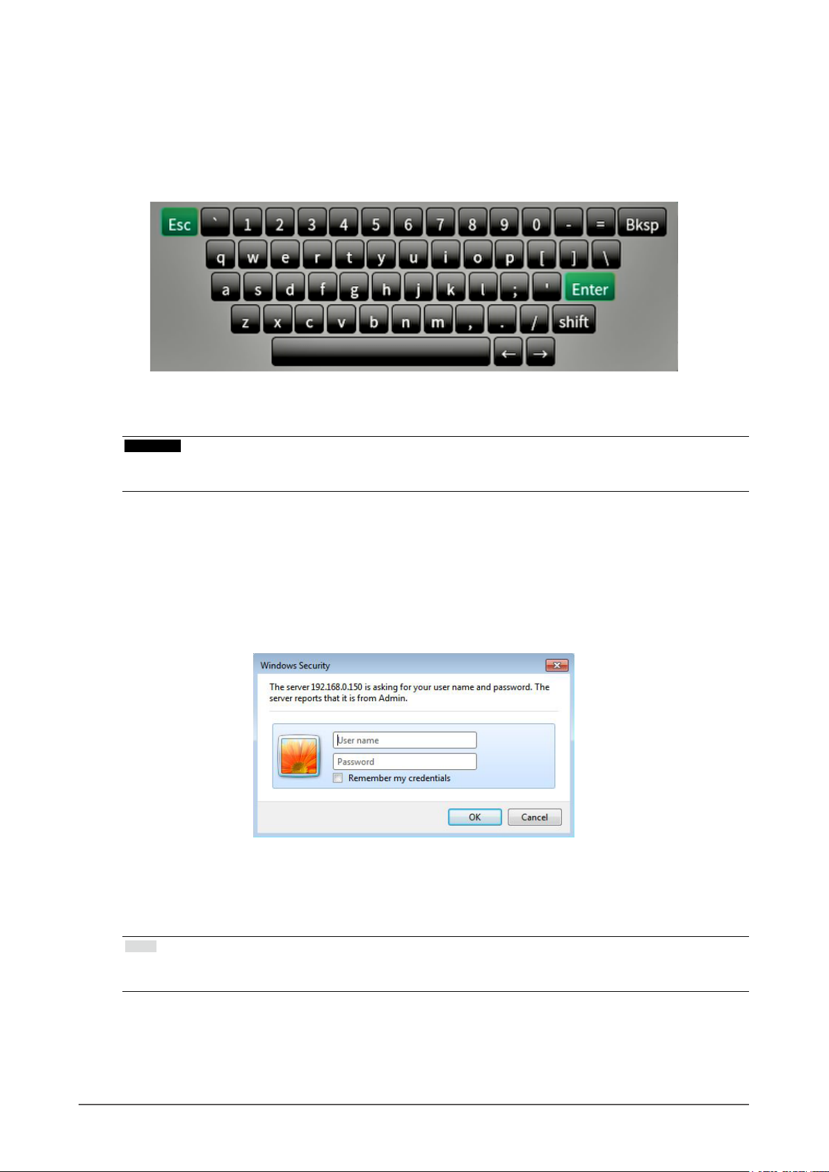
Entering characters
• When entering using a USB keyboard
Typed characters are entered in the text box.
• When entering using a USB mouse
Clicking an item that requires characters to be input, such as a text box, will display a software keyboard.
When the focus is moved out of the software keyboard, the software keyboard is hidden.
Conguring from a web browser
●
Attention
• It is recommended you use Internet Explorer 11 as your web browser.
• When conguring from the web browser, the power supply must be connected to this product.
Start the web browser of the PC to be used.
1.
Enter the following address for access.
2.
Address: http://Address of this product
*1 The default address for access is http://192.168.0.150.
The login screen is displayed.
Enter a username and a password.
3.
Select “OK”.
4.
The setting screen is displayed.
Note
• If you are unable to login, try using the following address.
http://address of this product/index.html
*1
Chapter 2 Before Conguration
9
Page 10
2-2. Setting Screen
The setting screen is comprised of “Basic Information”, “System Settings”, and “Live Image Screen
Settings”.
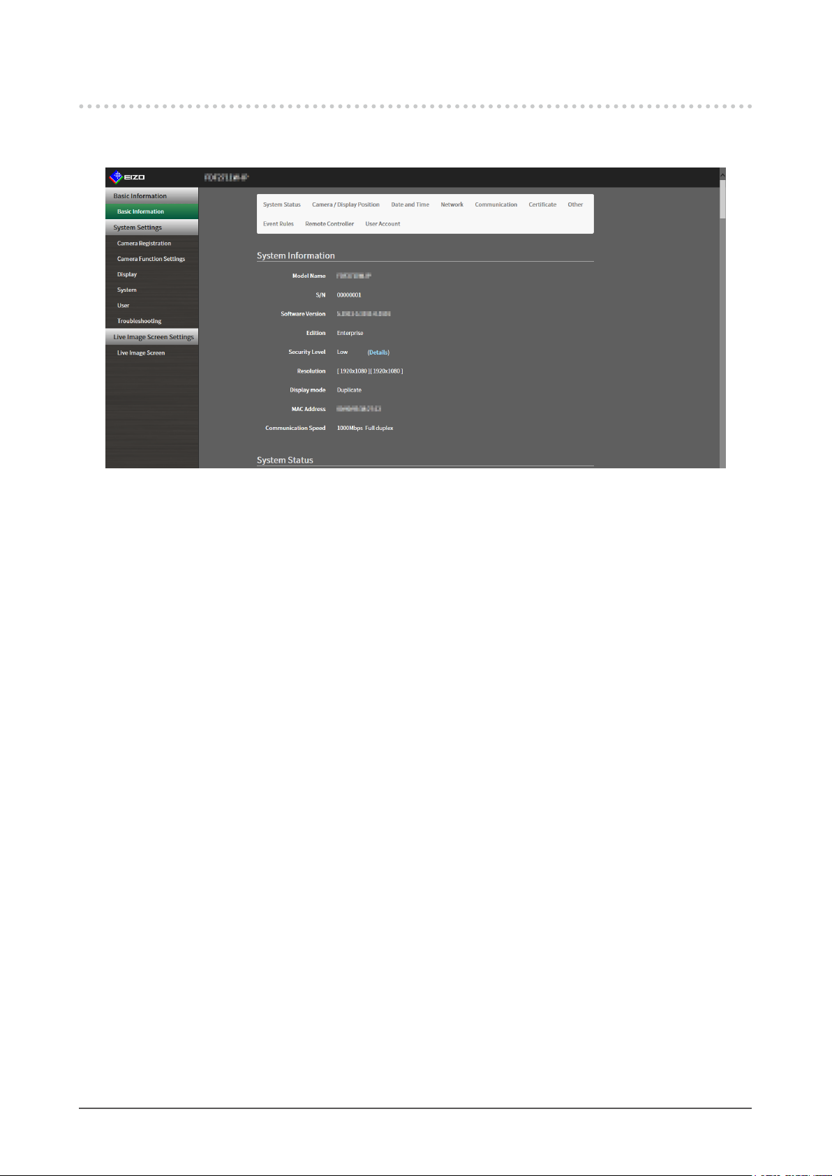
Basic Information
●
Information on various settings of this product is displayed in a list.
Clicking on an item tab at the top of the screen will display each setting item.
System Information
Displays the current status.
• Model Name
• S/N
• Software Version
• Edition
• Resolution
• Display mode
• MAC Address
• Communication Speed
• Security Level (Enterprise Edition only)
System Status / Camera / Display Position / Date and Time / Network /
Communication / Certicate / Other / Event Rules / Remote Controller / User
Account
The current setting status is displayed.
*1
*1 Only available for use if the edition is Enterprise.
System Settings
●
Various settings such as registration of network cameras and system settings are performed.
Live Image Screen Settings
●
Display settings such as changing the live image screen layout are performed.
Chapter 2 Before Conguration
10
Page 11
Chapter 3 System Settings
Perform settings for the date and time of the system, network settings, and maintenance.
These operations can be performed from the application screen or from the web browser.
This chapter explains the procedure using the web browser. However, except for a few functions, the same
functions can be used with either method.
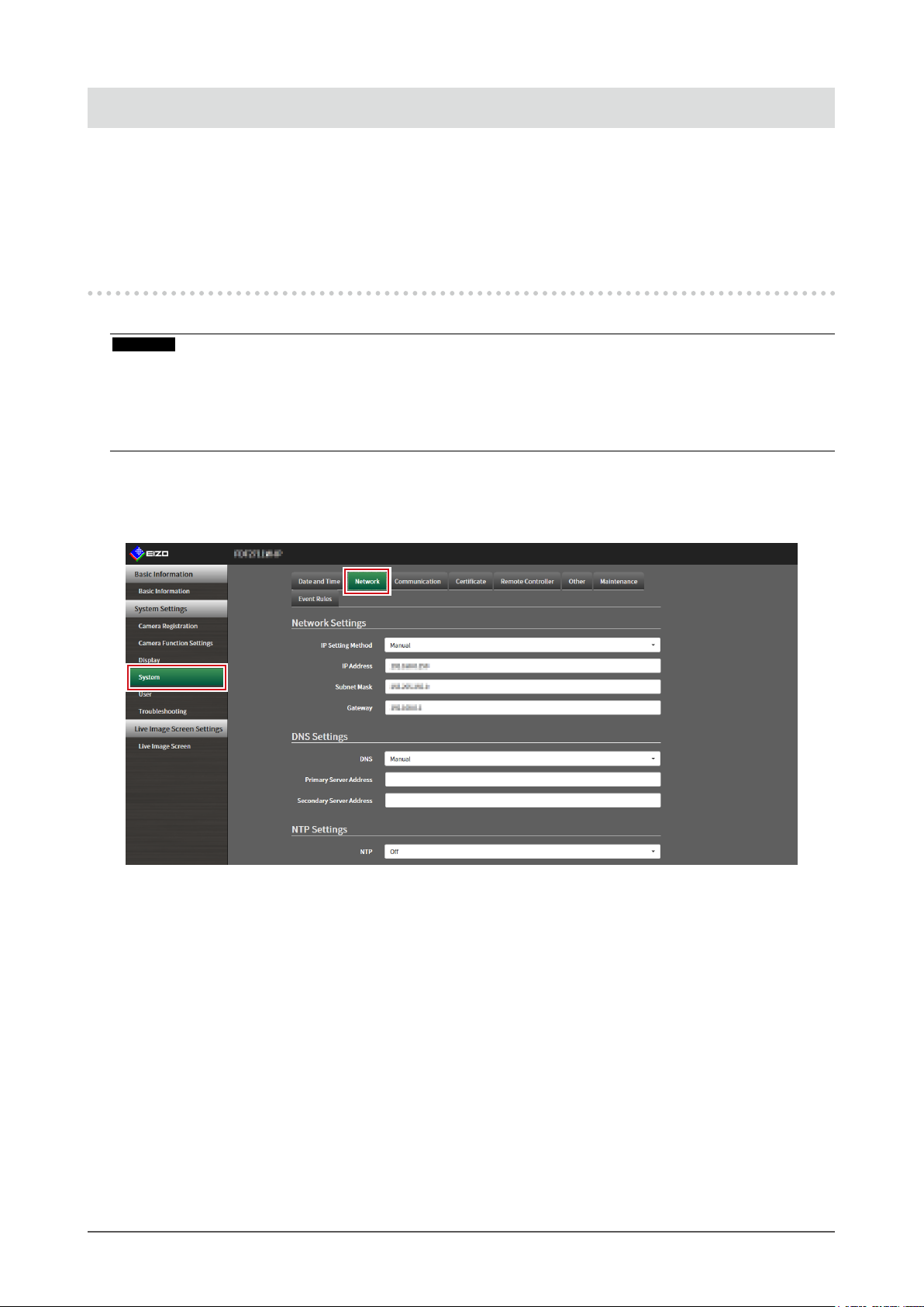
3-1. Performing Network Settings
Perform network settings such as IP address, DNS, and NTP.
Attention
• When any one of the IP address settings/IP address/subnet mask/gateway is changed and “Apply” is selected,
the warning message “The network settings will be changed.” is displayed.
Select “OK”.
• The same warning message is displayed when the IP address is changed from the web browser. Selecting “OK”
will display a message requesting reaccess. Access again using the changed IP address.
Select “Network” of “System”.
1.
The “Network” screen is displayed.
Chapter 3 System Settings
11
Page 12

Set the following items.
2.
Network Settings
Item Detail Setting range
IP Setting Method Select “IP Setting Method”. DHCP / Manual
IP Address
Subnet Mask
Gateway
*1 The initial address is “192.168.0.150”.
*2 If the environment does not include a gateway, it is not necessary to set “Gateway”. Either leave it as
*1
*2
default setting or set “0.0.0.0”.
When “Manual” is selected under “IP Setting Method”, “IP
Address”, “ Subnet Mask”, and “Gateway” can be set.
Attention
• Avoid duplicate IP addresses for devices on the same
network.
• If multiple units of this product are connected on the same
network, their IP addresses should be changed.
0.0.0.0 to
255.255.255.255
DNS Settings
Item Detail Setting range
DNS (Only when “Manual” is selected under “IP Setting Method”
of “Network Settings”)
Set “DNS”.
Primary Server
Address
Secondary Server
Address
When “Manual” is selected under “DNS”, set “Primary
Server Address” and “Secondary Server Address”.
Auto / Manual
0.0.0.0 to
255.255.255.255
NTP Settings
Item Detail Setting range
NTP Set whether to use the NTP server or not. On / O
Server Address When “On” is selected, set the NTP server address. Alphanumerics and
symbols
Select “Apply”.
3.
The setting complete screen is displayed.
Select “OK”.
4.
Chapter 3 System Settings
12
Page 13
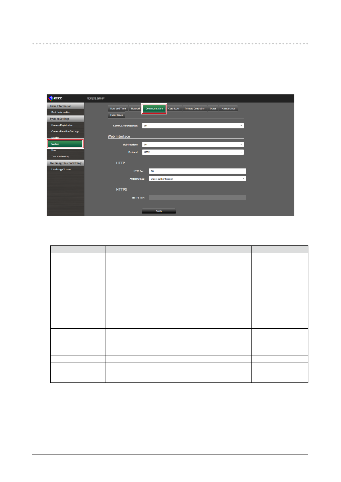
3-2. Performing Communication Settings
The communication settings are used to congure the web interface function and detection of
communication errors.
Select “Communication” of “System”.
1.
The “Communication” screen is displayed.
Set the following items.
2.
Item Detail Setting range
Comm. Error Detection Set the message display timing when the reception of video
image data stops.
On:
Within several seconds after the reception of video image
data stops, an alert message is displayed in a red box on the
live image screen. When communication resumes, the alert is
cleared and the video image is displayed again.
O:
When approx. 30 seconds have elapsed after the reception
of video image data stops, a communication error message is
displayed.
Web Interface Enables operation and setting of the product over the network
from a web browser.
Protocol Select protocol for communication with the web server.*
HTTP Port Set the HTTP port of the web interface. 80, 1024 to 65535
AUTH Method Set the authentication method for the web interface.*
HTTPS Port Set the HTTPS port of the web interface. 443, 1024 to 65535
*1 If “USB Lock” is “On” and “Remote Controller Lock” is “On”, it cannot be set to “O”.
*2 Depending on the protocol selected, the address may be dierent when accessing this product from the
web browser.
“HTTP”: http://address of this product
“HTTPS”: https://address of this product
“HTTP and HTTPS”: can be accessed from either of the above
*3 Can be set when either “Self-Signed Certicate” or “CA-Signed Certicate” is selected in “Certicate”.
*4 Cannot be set when “User Account” is “LDAP”.
2
4
On / O
On / O
HTTP / HTTPS*3 /
HTTP and HTTPS
Digest authentication /
BASIC authentication
*1
*3
Chapter 3 System Settings
13
Page 14
Select “Apply”.
3.
The setting complete screen is displayed.
Select “OK”.
4.
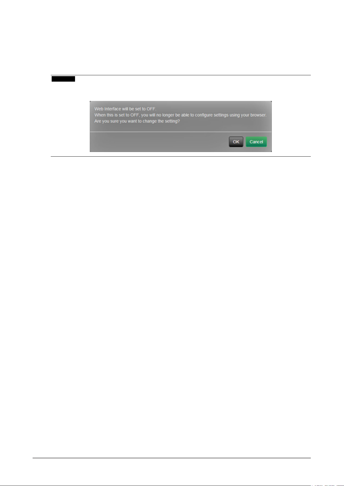
Attention
• When “Web Interface” is set to “O”, the settings cannot be congured from the web browser.
• When “Web Interface” is set to “O” and “Apply” is selected, the following warning message is displayed.
Chapter 3 System Settings
14
Page 15
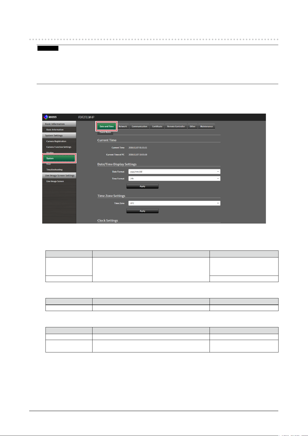
3-3. Setting the Current Date and Time
Attention
• Set the correct dates. Incorrect dates may result in failure of secure communication during certicate validation.
If you use SSL for communication with the camera or LDAP setting, avoid the state of power turned o for a long
time of period or make sure correct time is set using NTP.
• If secure LDAP communication is not established, you can not login. Reset the account setting using the Reset
button.
Select “Date and Time” of “System”.
1.
The “Date and Time” screen is displayed.
Set the current date and time.
2.
Date/Time Display Settings
Item Detail Setting range
Date Format Set the date format and time format. yyyy/mm/dd, Mmm/dd/yyyy, dd/
Mmm/yyyy, mm/dd/yyyy, dd/
mm/yyyy
Time Format 24h / 12h
Time Zone Settings
Item Detail Setting range
Time Zone Set the time zone. Region / city
Clock Settings
Item Detail Setting range
Procedure
Date and Time Set the current time. 2018/1/1 0:00 to 2035/12/31
*1 This can be set only when displayed on the web browser.
*1
Select the time setting procedure. Manual / Synchronize with PC
23:59
Chapter 3 System Settings
15
Page 16

Select “Apply”.
3.
The setting complete screen is displayed.
Select “OK”.
4.
Note
• When “Synchronize with PC” is selected for “Procedure”, the current date and time information of the
computer is transmitted to this product.
• If the system is not connected to the power supply for one week or longer, the date and time displayed on this
product will become incorrect. If such a situation occurs, reset the date and time.
Chapter 3 System Settings
16
Page 17

3-4. Other System Settings
Perform the following settings: “Language”, “Resolution”, “ Multi-Monitor”, “Key Lock”, “ USB Lock”,
“Remote Controller Lock”, “Power Indicator”, and “Keyboard Layout”.
Select “Other” under “System”.
1.
The “Other” screen is displayed.
Set the following items.
2.
Item Detail Setting range
Language Set the display language of the menu and the setting
screen.
Resolution Select an output resolution to the monitor. 1920x1080 / 2560x1440 /
Multi-Monitor Select the method for outputting the signal from the HDMI
connector 2.
Key Lock Locks operations by the buttons on the front of this
USB Lock
Remote Controller
Lock
Power Indicator Sets whether to turn the power indicator (blue) on or o
Keyboard Layout Select the keyboard arrangement. Japanese / English(US) /
*1 This can be set only when displayed on the web browser.
*2 When the setting of “USB Lock” is changed, the product needs to be restarted.
Select “Apply”.
3.
The setting complete screen is displayed.
*1, 2
*1
product.
Locks operations of the USB device. On / O
Lock the operation of the remote control. (A function for
use with models equipped with a remote control)
under normal operation.
/ English / Deutsch
日本語
3840x2160
Single / Extended / Duplicate
On / O
On / O
On / O
English(UK) / German
Select “OK”.
4.
Chapter 3 System Settings
17
Page 18
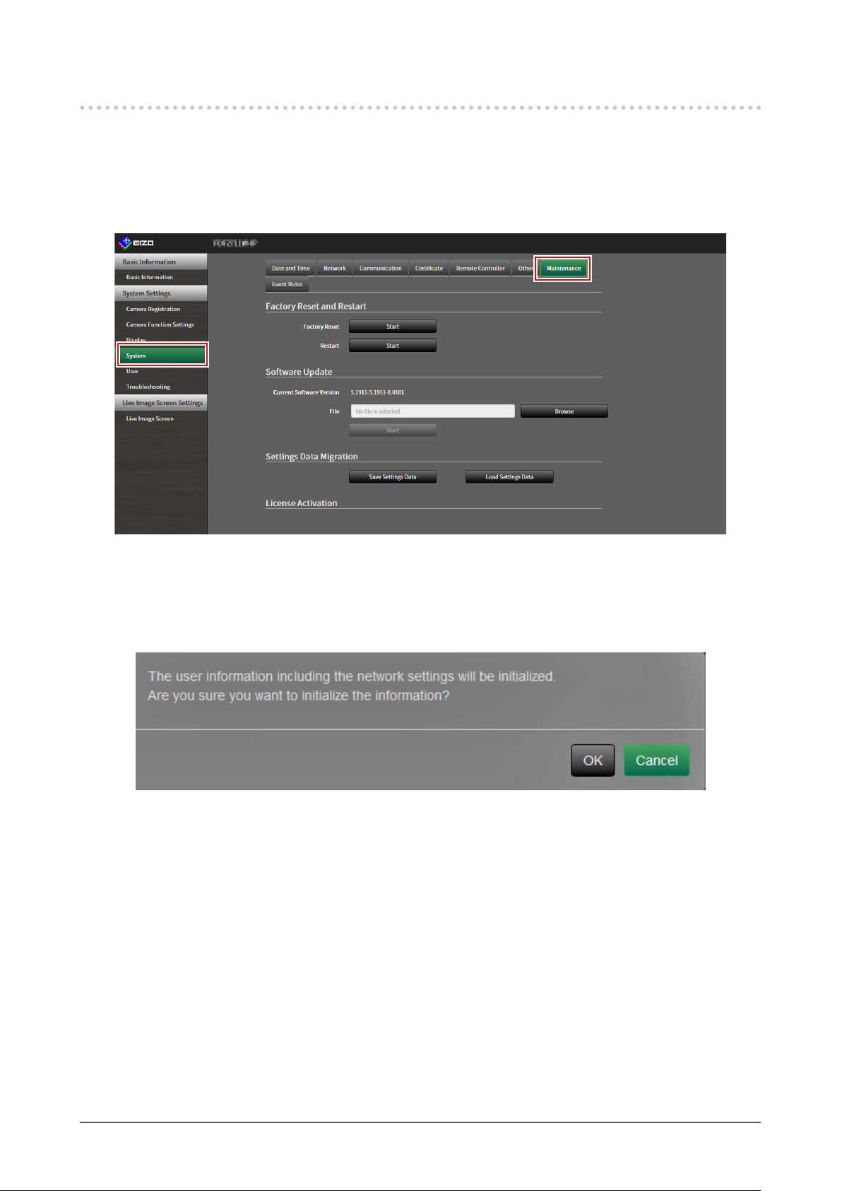
3-5. Initializing the System
All settings are returned to default except for system logs, operation logs, the current time, time zone
settings, license activation information, and the software version.
Select “Maintenance” of “System”.
1.
The “Maintenance” screen is displayed.
Select “Start” under “Factory Reset”.
2.
A conrmation message is displayed.
Select “OK”.
3.
Chapter 3 System Settings
18
Page 19
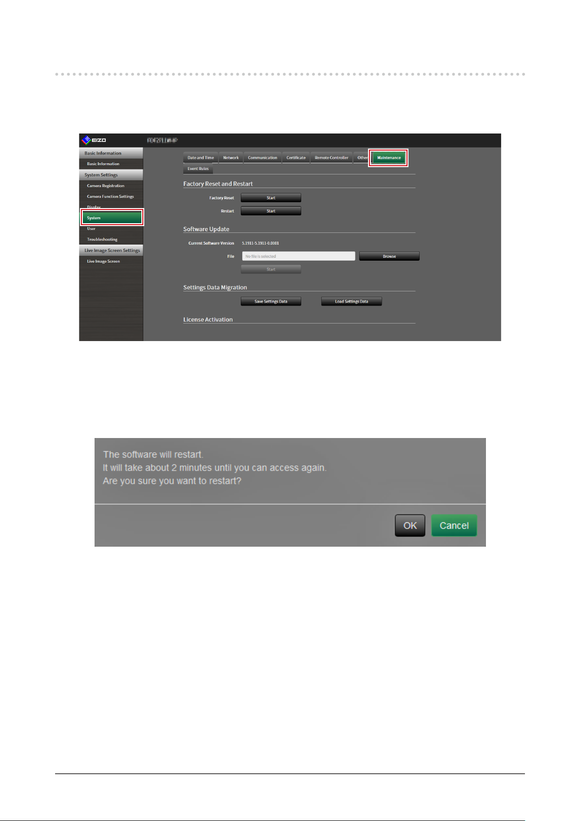
3-6. Restarting the System
Select “Maintenance” of “System”.
1.
The “Maintenance” screen is displayed.
Select “Start” under “Restart”.
2.
A conrmation message is displayed.
Select “OK”.
3.
The system will restart.
Chapter 3 System Settings
19
Page 20
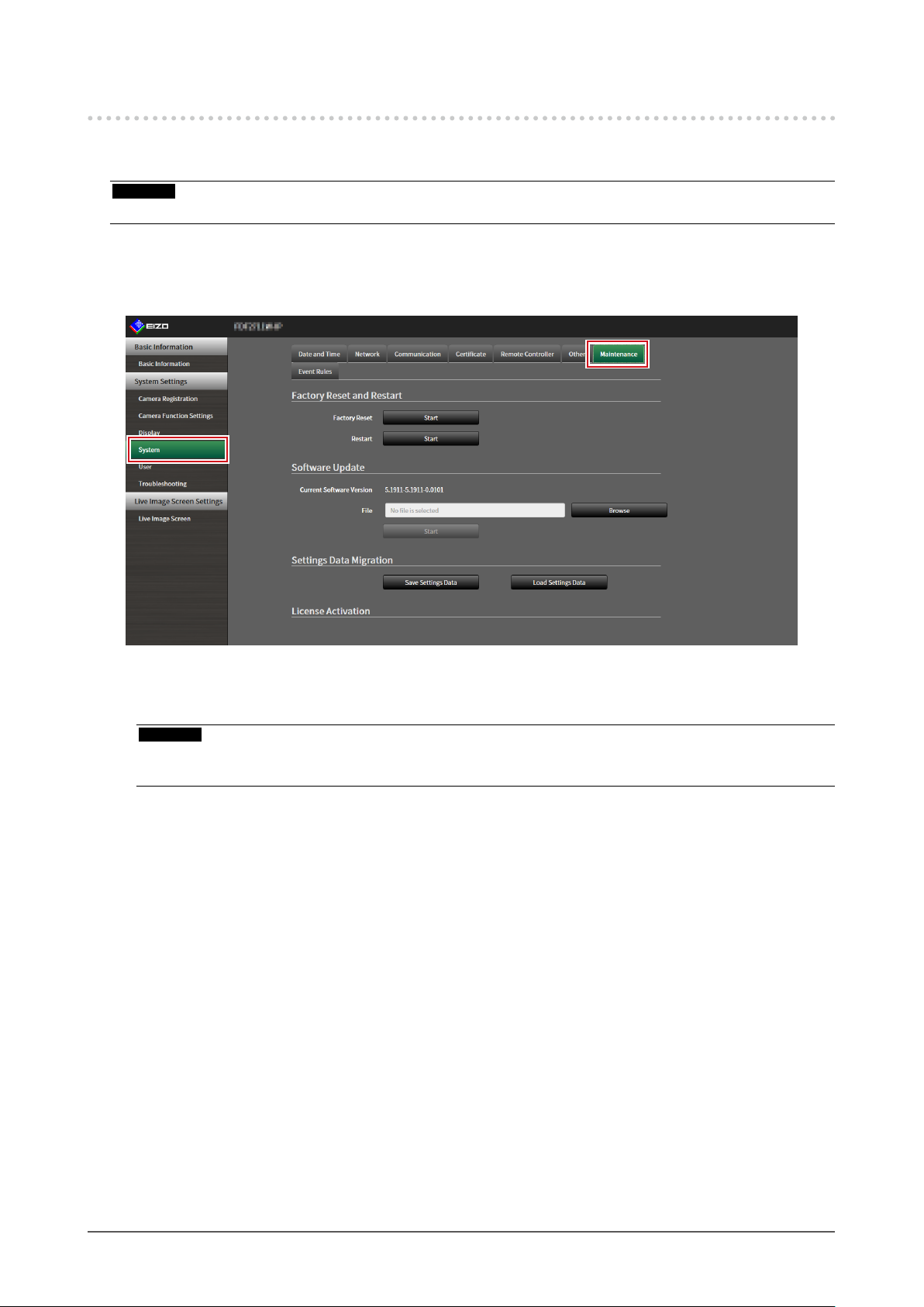
3 -7. Updating Software
The software version can be upgraded. Download the upgrade le from the EIZO website (www.
eizoglobal.com) ahead of time.
Attention
• This function can be used only when using the web browser.
Select “Maintenance” of “System”.
1.
The “Maintenance” screen is displayed.
Select the upgrade le.
2.
Select “Browse” under “Software Update” and set the le.
Attention
• The software will not be updated if a le is not selected, or a le other than an update le has been selected.
• Update the software only when the power supply is connected to the product.
Select “Start”.
3.
A conrmation message is displayed.
Chapter 3 System Settings
20
Page 21
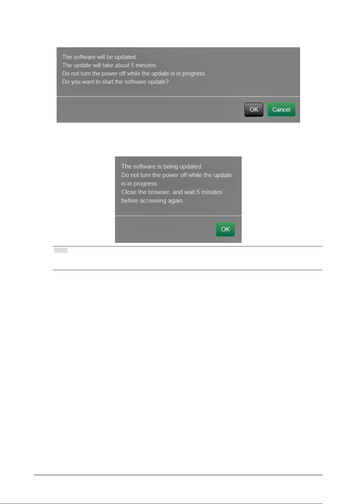
Select “OK”.
4.
A “Software is being updated” message is displayed.
Select “OK”.
5.
Note
• It takes approximately ve minutes to update the software.
• The red LED blinks while the software is updating.
Chapter 3 System Settings
21
Page 22

3-8. Saving Settings Data
Settings data can be exported to a le. The exported le can be used to transfer settings data.
Attention
• This function can be used only when using the web browser.
Select “Maintenance” of “System”.
1.
The “Maintenance” screen is displayed.
Select “Save Settings Data” under “Settings Data Migration”.
2.
The “Save Settings Data” dialog box is displayed.
Specify the “Password”.
3.
Select “Execute”.
4.
Specify the saving destination.
5.
The settings data is saved.
Attention
• Some of the settings cannot be saved.
• If the password specied when saving the data is forgotten, it will no longer be possible to load the settings
data.
Note
• Saved le name: dx0211-ip_Backupyyyymmdd.duraconf2 (yyyymmdd is the save date.)
Chapter 3 System Settings
22
Page 23

3-9. Loading System Settings Data
Load settings data from a le.
Attention
• This function can be used only when using the web browser.
Note
• Regardless of the software version, it is possible to switch the LDAP settings.
Select “Maintenance” under “System”.
1.
The “Maintenance” screen is displayed.
Select “Load Settings Data” under “Settings Data Migration”.
2.
The “Load Settings Data” dialog box is displayed.
Select the settings data le.
3.
Select “Browse” and set the le.
Chapter 3 System Settings
23
Page 24

Enter the password that was specied when saving the settings data in
4.
“Password”.
Select the data to be loaded.
5.
Place a check mark in the check box.
Select “Execute”.
6.
When loading is completed, a message is displayed.
Select “OK”.
7.
Attention
• If the environment where settings data was saved is dierent from the environment where settings data
is loaded with respect to network settings or communication settings, you may not be able to display the
settings screen from the web browser.
Chapter 3 System Settings
24
Page 25

3-10. Performing License Activation
The software edition can be changed. Usable functions are added for Enterprise Edition. For details,
contact your dealer or local EIZO representative.
Attention
• This function can be used only when using the web browser.
Select “Maintenance” of “System”.
1.
The “Maintenance” screen is displayed.
Select “Browse” for “License Activation”, and select the license le.
2.
Select “Activate”.
3.
A conrmation message is displayed.
Select “OK”.
4.
“Current Edition” is updated to Enterprise.
Close the browser and wait 2 minutes before accessing again.
Chapter 3 System Settings
25
Page 26

3-11. Setting Event Rules
Actions to be executed when “Alert request received”, “Timer expired”, and “Video output status change”
events occur can be set.
Note
• A total of 16 individual Event Rules can be set.
Select “Event Rules” of “System”.
1.
The “Event Rules” screen is displayed.
Select the number for registering the Event Rule.
2.
Place a check mark in the check box of the number to be registered.
Select “Setting”.
3.
The “Event Rules” screen is displayed.
Chapter 3 System Settings
26
Page 27

Set Event Rules.
4.
Item Detail Setting range
Name Enter the name of the Event Rule. Alphanumeric, kana*1, and
Status Select whether to enable or disable the Event Rule. Active / Inactive
Event Select an event to trigger an action.
The items that can be set dier depending on the event.
Refer to the tables below.
Action Select the actions to be executed when an event
occurs. The items that can be set dier depending on
the action. Refer to the tables below.
*1 This can be set only when displayed on the web browser.
*1
kanji
(Up to 24 characters)
Alert request received / Timer
expired / Video output status
change
Notication / Start a timer
Alert request received
Item Detail Setting range
Camera No. Select the camera to receive the alert. Any camera, from 1 to 48
Trigger Type Select whether to enable or disable the Event Rule. any / On / O
Timer expired
Item Detail Setting range
Timer No. Select the number of the timer. 1 to 8
Notication
Item Detail Setting range
Protocol Select the communication protocol. HTTP / HTTPS
URL Enter the URL of the notication destination. Alphanumerics and symbols (up
to 32 characters)
Username Enter the username for accessing the URL. Alphanumerics and symbols (up
to 32 characters)
Password Enter the password for accessing the URL. Alphanumerics and symbols (up
to 32 characters)
Execute Performs a conrmation test in order to access the
specied URL.
Start a timer
Item Detail Setting range
Timer No. Select the number of the timer. 1 to 8
Duration Set “Minute” and “Second”. “Minute”: 0 to 59, “Second”: 0 to
59
Select “OK”.
5.
The settings are complete.
Chapter 3 System Settings
27
Page 28

3-12. Performing Certicate Settings
Select “Certicate” of “System”.
1.
The “Certicate” screen is displayed.
Perform certicate settings.
2.
Server Certicate
The Server Certicate is used when accessing this product from the web browser via HTTPS.
Attention
• A Certicate Signing Request (CSR) cannot be created with this product.
• CA-Signed Certicate registration is only possible via web browser.
Select “Typ e”, and the select “Apply”.
• Self-Signed Certicate
Press the “Generate” button of the “Self-Signed Certicate” eld to generate a certicate, and then select it.
• CA-Signed Certicate
Press the “Register” button of the “CA-Signed Certicate” eld to register a certicate, and then select it.
Registration of information issued from the certifying body is required for registration.
Chapter 3 System Settings
28
Page 29

Root Certicate
The Root Certicate is used when performing an HTTPS connection with network cameras from this
product, or when performing an LDAPS connection to the LDAP server.
Attention
• Root Certicate registration is only possible via web browser.
• A Root Certicate is not pre-installed in this product.
Select “Register”, and the select “Root Certicate”.
Chapter 3 System Settings
29
Page 30

3-13. Setting the Remote Control ID
This function is for use with models equipped with a remote control.
When using multiple units of this product, the product operated by a remote control can be limited by
specifying the ID shared by the product and remote control. With the factory values, all products that
receive the remote control signal will operate accordingly.
Setting the product ID
●
Select “Remote Controller” of “System”.
1.
The “Remote Controller” screen is displayed.
Set the following items.
2.
Item Detail Setting range
ID Select the number that will be the ID. 0 to 99
Display ID When set to “On”, the ID is displayed in the upper right
of the Live Image Screen when the ID button of the
remote control is pushed.
Select “Apply”.
3.
The settings are complete.
On / O
Chapter 3 System Settings
30
Page 31

Setting the remote control ID
●
Press and hold for more than 3 seconds.
1.
With pressed, enter the ID (0 to 99) you want to set with the number buttons.
2.
Note
• If the ID you want to set is a single digit number, enter 0 before it.
(Ex: To set “3”, enter “03”.)
Release .
3.
Note
• When conrming the ID of the remote control, set “Display ID ” to “On”, and press .
The current ID is displayed in the upper right of the Live Image Screen.
3-14. Checking Logs
This system records operation logs and system logs. They can be used to check the current or past
conditions of the system or to nd out the cause when a problem occurs.
Select “Log Display” of “Troubleshooting”.
1.
The “Log Display” screen is displayed.
Select “Operation Log Display” or “System Log Display”.
2.
The log is displayed in the lower area.
Chapter 3 System Settings
31
Page 32

3-15. Saving Logs
Save operation logs and system logs.
Use these logs to check the current or past conditions of the system or to nd out the cause when a
problem occurs.
Attention
• This function can be used only when using the web browser.
Select “Log Display” of “Troubleshooting”.
1.
The “Log Display” screen is displayed.
Select “Operation Log Display” or “System Log Display”.
2.
The log is displayed in the lower area.
Select “Save”.
3.
The saving destination dialog box is displayed.
Select a saving destination.
4.
Select “Save”.
5.
Chapter 3 System Settings
32
Page 33

3-16. Performing Camera Connection Conrmation
The connection status of the network cameras can be conrmed.
Attention
• This function can be used only when using the web browser.
Select “Connection Conrmation” of “Troubleshooting”.
1.
The “Connection Conrmation” screen is displayed.
Select “Camera Name”.
2.
Select “Run” for “ping” or “traceroute”.
3.
The connection status is displayed in the lower area.
Chapter 3 System Settings
33
Page 34

3 -17. Conrming Network Connection Status
Select “Network Connection Status” of “Troubleshooting”.
1.
The “Network Connection Status” screen is displayed.
Select “Current Status”.
2.
The connection status is displayed in the lower area.
Note
• Select “Reconnect” to reset the network status. The connection status is not displayed.
Chapter 3 System Settings
34
Page 35

Chapter 4 Management of Network
Cameras
This section describes the procedure for network camera registration and function settings, and to reect
them on the system.
These operations can be performed from the application screen or from the web browser.
This chapter explains the procedure using the web browser. However, except for a few functions, the same
functions can be used with either method.
4-1. Registering the Network Cameras
Select “Camera Registration”.
1.
A screen is displayed to show a list of camera registration information.
Select a position where the camera is to be registered.
2.
Place a check mark on the check box of the position number where the camera is to be registered.
Select “Manual Registration” in the lower part of the screen.
3.
The “Camera Information Settings” dialog box is displayed.
Chapter 4 Management of Network Cameras
35
Page 36

Set each item and select “OK”.
4.
Item Detail Setting range
*10
*10
*1
Enter the camera name. If “Obtain Camera Name” is
selected, the camera name is automatically obtained from
the network camera.*
2
• If “Protocol” is “DirectUri”, “Obtain Camera Name” cannot
Alphanumeric,
*3
kana
, and
*3
kanji
(Up to 24
characters)
be used.
255.255.255.255
command).
Provides secure communication.
Select certicate validation during SSL communication.
Attention
On / O
• If “Certicate Validation” is “On,” the Root Certicate of the
network camera must be registered in “Root Certicate” of
“Certicate”.
ONVIF / DirectUri
*6
Enter the user name to be used to access the network
camera.
Alphanumerics and
symbols (Up to 32
characters)
*6
Enter the password to be used to access the network
camera.
Alphanumerics and
symbols (Up to 32
characters)
*7
Select the media prole of the network camera.
Select “Obtain Prole” to obtain a list of proles from the
network camera.
*7
Select the mode for transmitting camera video images. Unicast / Multicast
EIZO_Prole /
Prole of each
camera
Set the URI that starts with rtsp:// or rtp://. Alphanumerics (Up
to 1023 characters)
RTP over RTSP
Select a stream format. 1 / 2 / 3 / 4
Select a stream channel. 1 / 2 / 3 / 4
*10
Select whether or not PTZ operation is enabled for the
On / O
camera that supports RS 485 communication.
*11
Select a video stream format. Depends on the
camera
*11
Select a stream prole. Depends on the
camera
Camera Name
IP Address Enter the IP address of the network camera. 0.0.0.0 to
“Ping” button Executes a connection test with the camera (i.e. ping
Port Enter the port number of the network camera. 1 to 65535
*5
SSL
Certicate Validation
Protocol Select the protocol to control cameras. Panasonic / AXIS /
Username
Password
Media Prole
Transmission Mode
*8
URI
Comm. Method Select the communication method for camera video images. RTP over UDP
Stream
Channel
RS485PTZ Control
Video Stream
Stream Prole
*4
*9
/
Chapter 4 Management of Network Cameras
36
Page 37

*1 This can be obtained only when “IP Address”, “Port”, “ Username”, and “Password” are input.
*2 If “Protocol” is “DirectUri,” the “Obtain Camera Name” button is not displayed.
*3 This can be input only when displayed on the web browser.
*4 When “Protocol” is set to “DirectUri” and “URI” starts with rtp://, the setting range will be 1024 to 65534.
*5 Can only be set if “Protocol” is “Panasonic” or “AXIS”.
*6 Enter the username and password of the user who has the administrator’s rights. For details, refer to the
network camera User’s Manual.
*7 This can be set only when “Protocol” is set to “ONVIF”.
*8 This can be set only when “Protocol” is set to “DirectUri”.
*9 In the following cases, it is only possible to set “RTP over UDP”.
• In the case where “Protocol” is set to “ONVIF” and “Transmission Mode” is set to “Multicast”
• In the case where “Protocol” is set to “DirectUri” and “URI” starts with rtp://
*10 This can be set only when “Protocol” is set to “Panasonic”.
*11 This can be set only when “Protocol” is set to “AXIS”.
Returns to the screen that shows a list of camera registration information in the step 1 above.
Select “Apply”.
5.
A conrmation message is displayed.
Select “OK”.
6.
Note
• If there is a failure in obtaining “Obtain Camera Name” or “Obtain Prole” information, the following message
is displayed. Try obtaining the information again.
Chapter 4 Management of Network Cameras
37
Page 38

4-2. Changing Network Camera Information
Select “Camera Registration”.
1.
A screen is displayed to show a list of camera registration information.
Select the position number of the camera to be changed.
2.
Place a check mark on the check box of the position number of the camera to be changed.
Select “Manual Registration”.
3.
The “Camera Information Settings” dialog box is displayed.
Set each item and select “OK”.
4.
Returns to the camera registration information list screen in step 1.
Note
• For details, refer to step 3 under “4-1. Registering the Network Cameras” (page 35).
Chapter 4 Management of Network Cameras
38
Page 39

Select “Apply”.
5.
A conrmation message is displayed.
Select “OK”.
6.
Note
• If there is a failure in obtaining “Obtain Camera Name” or “Obtain Prole” information, the following message
is displayed. Try obtaining the information again.
Chapter 4 Management of Network Cameras
39
Page 40

4-3. Auto Discovery of Network Cameras
Network cameras installed on the same network as this product can be automatically detected and
registered.
Select “Camera Registration”.
1.
A screen is displayed to show a list of camera registration information.
Select “Auto Discovery” in the lower part of the screen.
2.
Select “Protocol”.
3.
Select from “Panasonic”, “AXIS”, and “ONVIF”.
Enter the network camera “Username” and “Password”, and select “OK”.
4.
Displays the detection results.
Place a check in the camera to register, and select “Add”.
5.
The camera is registered.
Select “Apply”.
6.
Chapter 4 Management of Network Cameras
40
Page 41

4-4. Deleting Network Cameras
Select “Camera Registration”.
1.
A screen is displayed to show a list of camera registration information.
Select the camera to be deleted.
2.
Place a check mark on the check box of the position number of the camera to be deleted.
Select “Delete” in the lower part of the screen.
3.
A conrmation message is displayed.
Select “OK”.
4.
Returns to the screen that shows a list of camera registration information.
Select “Apply”.
5.
A conrmation message is displayed.
Select “OK”.
6.
Chapter 4 Management of Network Cameras
41
Page 42

4-5. Exporting Network Camera Information
The list of camera registration information can be saved in a CSV le.
The exported le can be used when transferring network camera information.
Attention
• This function can be used only when using the web browser.
Select “Camera Registration”.
1.
A screen is displayed to show a list of camera registration information.
Select “Save Camera Information”.
2.
A message regarding CSV le download is displayed at the bottom of the screen.
Select “Save”.
3.
A CSV le containing the camera information displayed in the information list is exported.
Note
• Saved le name: dx0211-ip_CameraInfo_yyyymmdd.csv(yyyymmdd is the computer date and time.)
Chapter 4 Management of Network Cameras
42
Page 43

4-6. Importing Network Camera Information
A CSV le that contains additional camera candidates can be imported and used for registration.
Attention
• This function can be used only when using the web browser.
Select “Camera Registration”.
1.
A screen is displayed to show a list of camera registration information.
Select “Load Camera Information”.
2.
A le selection dialog box opens.
Select the CSV le that contains the network camera information and select
3.
“Open”.
A list of the candidate network cameras appears.
Select a camera to be added from the list of candidates and select “Add”.
4.
Returns to the camera registration information list screen in step 1.
Chapter 4 Management of Network Cameras
43
Page 44

Select “Apply”.
5.
A setting conrmation dialog box is displayed.
Select “OK”.
6.
Note
• Up to 255 candidate cameras can be read.
• The CSV les that can be read are as follows.
- CSV les exported from the web browser
- CSV les created by the user
• For details on how to export CSV les, refer to “4-5. Exporting Network Camera Information” (page 42).
Chapter 4 Management of Network Cameras
44
Page 45

4 -7. Setting Network Camera Time
Adjust the time of the network camera to the time of this product.
Attention
• Cannot be set if the camera does not support this function.
• Can only be set when “Protocol” is “Panasonic” or “ONVIF” during camera registration.
Select “Camera Function Settings”.
1.
The “Camera Function Settings” screen is displayed.
Select a network camera to be set from “Camera Name”.
2.
Information on the selected network camera is displayed.
Select “Execute” for “Camera Info. Display/Clock Settings”.
3.
The clock is synchronized.
Note
• The following settings are possible when “Protocol” of the registered camera is “Panasonic”.
- Camera Information Display
- Time Display
- Display Position
Chapter 4 Management of Network Cameras
45
Page 46

4-8. Setting Quality of Transmission Video Images
Set the quality of video images transmitted from the network cameras.
Note
• This product supports H.264, H.265 (Panasonic only), and MJPEG video compression formats.
Attention
• When devices such as recorders are connected to a network camera, the display and recording of such devices
may be aected.
• Setting cannot be performed if “Protocol” is a “DirectUri” network camera.
Select “Camera Function Settings”.
1.
The “Camera Function Settings” screen is displayed.
Select a network camera to be set from “Camera Name”.
2.
Information on the selected network camera is displayed.
Chapter 4 Management of Network Cameras
46
Page 47

Set the following items under “Video Settings”.
3.
Protocol
Panasonic
√
√
√
AXIS
*3
*3
*4
√ √
√ √
√ √
√ √ √
*3
√
*3
√
*3
√
*3
√
*3
√
*3
√
√ √
√ √
√ √
√ √
√
ONVIF
√
√
*3
√
√
√
√
*3
√
*3
*3
*3
Media Prole Select the prole. EIZO_Prole / Prole
Encoder Select the encoder settings. According to the
Compression Format Select the compression format. H.264 / H.265 /
Resolution Set the resolution. According to the
Frame Rate Set the frame rate (video image update
Encoding Interval Set the encoder interval. According to the
Bit Rate (Max.) Set the maximum bit rate. 0 to 8192 kbps
Video Quality Set the image quality. The higher the
GOV Length
H.264 Prole
Comm. Method The communication methods for
Transmission Mode Select the transmission mode. Unicast / Multicast
Multicast Address*2Set the Multicast address for Multicast
Multicast Port
Multicast TTL
Refresh Interval Set the refresh interval (I-frame
Item Detail Setting range
inter val).
value, the higher the image quality.
*1
*1
*2
*2
Set the I-frame interval. According to the
Select a H.264 standard prole. Baseline / Main /
camera video images are displayed.
transmission.
Set the Multicast port number for
Multicast transmission.
Set the network TTL value for
Multicast transmission.
interval) of images.
Transmission Priority Set the video bit rate transmission
√
*5
√
Bit Rate (Min.) Set the minimum bit rate for the video
priority.
to be transferred.
Image Quality Set the image quality for the video to
*6
√
√
√
*3
√
*3
√
√
Video Stream Select the display mode to be used by
Stream Prole Select the prole that the camera has. EIZO_Prole / Prole
Rotation Select the rotation direction of the
GOP Length
Priority
*1
*1
be transferred.
the camera display.
images.
Select the GOP length for the video. According to the
Sets the priority for video compression. None / Frame Rate /
*1 Displayed when “H.264” is selected for “Compression Format”.
*2 Displayed when “Multicast” is selected for “Transmission Mode”.
*3 Read Only
*4 Can only be adjusted when “Transmission Priority” is “Frame Rate”
*5 Can only be adjusted when “Transmission Priority” is “Best Eort”
*6 Can only be adjusted when “Transmission Priority” is other than “Frame Rate”
of each camera
camera specications
MJPEG
camera specications
According to the
camera specications
camera specications
According to the
camera specications
camera specications
Extended / High
RTP over UDP / RTP
over RTSP
224.0.0.0 to
239.255.255.255
1824 to 65534: even
numbers only
According to the
camera specications
0.2 to 5 seconds
Constant Bit Rate /
Frame Rate / Best
Eort
0 to 8192 kbps
Fine (prioritize image
quality) / Normal / Low
(prioritize motion)
According to the
camera specications
of each camera
0 / 90 / 180 / 270
camera specications
Quality
Chapter 4 Management of Network Cameras
47
Page 48

Note
• If “Protocol” of the network camera is set to “DirectUri”, setting contents are displayed.
• The following settings are possible in “Other” when “Protocol” is “Panasonic” during camera registration.
- Pan/Tilt-ip
- Upside-down
- Lamp Display
Select “Apply”.
4.
The setting complete screen is displayed.
Select “OK”.
5.
Attention
• Depending on the network camera, some set values may not be reected. Check the specications of the
camera.
• When changes are made to image quality settings such as resolution, the image quality of other recording
devices and display devices using the same “Encoder” may be aected.
• Check the impact of changes to the image quality settings before conguring the settings.
Chapter 4 Management of Network Cameras
48
Page 49

Chapter 5 Live Image Screen Settings
In the live image screen settings, display settings such as changing the live image screen layout are
performed.
5-1. Setting Display Positions of Camera Video Images
Set the display position for video images from the network camera.
You can switch the display positions of the source and destination camera images by dragging and
dropping the camera name.
Note
• It is possible to set all the display positions of the registered network cameras.
Select “Display Position Settings” of “Display”.
1.
The “Display Position Settings” screen is displayed.
1
2
No. Description
1 A group of cameras displayed at the same time in the video image display area.
2 The position of a camera displayed in the video image display area. The registered camera name is
displayed.
Chapter 5 Live Image Screen Settings
49
Page 50

Select the layout of the live image screen.
2.
Select one from the “Layout” list box.
Note
• When a layout is selected, the display on the page changes to the selected state. You can set the layout while
imagining the display status.
• The initial display position when the screen is transitioned is the display position currently set for this product.
Select the name of the camera to move, and drag and drop the name on the
3.
position of the destination camera name.
The display positions of the source and destination camera video image are switched.
Example: 4-screen layout
1. Select “Display Position 1” for page 1.
2. Drag and drop it at “Display Position 5” on page 2.
The “Display Position 1” camera and “Display Position 5” camera are switched.
Only the camera name in the inner square is moved. The display position of the camera video image does
not move.
Select “Apply”.
4.
The display positions of camera video images are updated. When “Reset” is selected, the information
of the setting being changed is discarded and the setting is reset to the current display setting of the
product.
Note
• If displayed on the web browser screen, a camera web page link is embedded in the frame where a camera
name is assigned. (Excluding network cameras with their “Protocol” set to “DirectUri”.)
Click the camera name, and a camera web page is displayed in a separate window.
Chapter 5 Live Image Screen Settings
50
Page 51

5-2. Setting Display Methods of Camera Video Images
Perform settings for whether to display or hide the camera name, specifying the screen switching interval,
and aspect ratio.
Select “Other Display Settings” of “Display”.
1.
The “Other Display Settings” screen is displayed.
Set the following items.
2.
Item Detail Setting range
Camera Name
Display
Sequence Inter val Set the interval for changing over the screen during sequential
Aspect Ratio Mode Set which aspect ratio to apply when the aspect ratio of the video
Select “Apply”.
3.
The setting complete screen is displayed.
Select “OK”.
4.
Select to display or hide the registered camera name on the live
image screen. (The camera name is displayed at the upper left of
the video image.)
display.
image delivered from the network camera is dierent from the
aspect ratio displayed in the image display area on the monitor. If
“Aspect” is selected when “Custom Screen” is selected for “Layout ”,
either “Full” or “Aspect” can be selected for each camera video
image. For details, refer to “5-3. Setting Custom Screen Layouts”
(page 52).
On / O
5 to 60 seconds
Full / Aspect
Chapter 5 Live Image Screen Settings
51
Page 52

5-3. Setting Custom Screen Layouts
Set the display layout when “Custom Screen” is selected in “Layout ” for the Live Image Screen.
Select “Custom Scr. Settings” of “Display”.
1.
The “Custom Scr. Settings” screen is displayed.
Note
• Click in the display position frame to x the display position of any camera image.
The display position for the specied camera image is maintained even if the pages are switched.
This function can only be used with “Custom Scr. Settings”.
Select the number of “row(s)” and “column(s)” from the list box.
2.
The screen will change to a layout with the selected number of columns and rows.
Drag a camera image display position and drop it on the display position you
3.
want to couple with.
The selected display position is coupled.
Select “Apply”.
4.
The display position coupling is updated. When “Reset” is selected, the information of the setting
being changed is discarded and the setting is reset to the current display setting of the product.
Note
• To release the coupling, click the display position just coupled. This can also be performed by changing the
number of columns and rows from the list box.
• If “Aspect Ratio Mode” is set to “Aspect”, “ Full” or “Aspect” is displayed for the camera display position, and
the setting changes every time either one of them is selected.
• For information on setting “Aspect Ratio Mode”, see “5-1. Setting Display Positions of Camera Video Images”
(page 49).
Chapter 5 Live Image Screen Settings
52
Page 53

5-4. Setting the Display Methods of Live Image Screens
Display settings such as changing the live image screen layout are performed.
Select “Live Image Screen Settings” of “Live Image Screen”.
1.
The “Live Image Screen Settings” screen is displayed.
Select each setting item from the list box.
2.
Item Detail Setting range
Full Screen
Display
Layout Set the layout to be displayed on the live image screen. 1 Screen / 3 Screens /
Page Set to switch the page of camera video images to display on the
Sequence Set to switch the page sequence display on or o. On / O
Select “Apply”.
3.
The setting complete screen is displayed.
Select “OK”.
4.
Set to display or hide the menu on the live image screen. On / O
4 Screens / 9 Screens /
16 Screens / 32 Screens /
8 Screens / Custom Screen
1 to 48
monitor.
Chapter 5 Live Image Screen Settings
53
Page 54

5-5. Setting Current Monitor Display Status
Select “System Status Settings” of “Live Image Screen”.
1.
The “System Status Settings” screen is displayed.
Click ▼ next to “Current Status” to select the status from the displayed list.
2.
Item Detail
Live Image Screen The monitor screen shows the Live Image Screen
Quick Shutdown The power is o
Setting Screen The monitor screen displays the Setting Screen
Note
• Click “Refresh Status” to obtain the current status of the monitor.
• Only “Refresh Status” is displayed on the application screen.
Chapter 5 Live Image Screen Settings
54
Page 55

Chapter 6 Management of the User
Account
Perform procedures such as registering, changing, and deleting user accounts (username, user level, and
password) used to access the system, and for conguring Auto Login settings.
Attention
• A maximum of ten persons can be registered for the user account. User information for a new user cannot be
registered when there are already 10 users registered.
• A username that is the same as an already registered user account cannot be registered.
• It is necessary to register at least one user with a user level of “ADMIN”.
• Enter the username with alphanumerics excluding “ : ”.
Note
• User levels include “LIVE”, “CAMERA CONTROL”, and “ADMIN”.
The operable range of this product diers by each level.
(√: Operable, -: Inoperable)
Operation
Level
LIVE √ √ √ √ -
CAMERA CONTROL √ √ √ √ ADMIN √ √ √ √ √
• The default settings of the user account are as follows.
- Username: “admin”
- Password: “admin”
- User Level: “ADMIN”
Menu display
Layout
change
Page change
Login
operation
6-1. Registering the User Account
Select “Local User” of “User”.
1.
The “Local User” screen is displayed.
System
settings
Chapter 6 Management of the User Account
55
Page 56

Select “Add”.
2.
A dialog box for setting the user account is displayed.
Set the user account.
3.
Item Description
Username Enter a username.
Enter the username with alphanumerics excluding “ : ”.
User Level Select “LIVE”, “ CAMERA CONTROL”, and “ADMIN”.
The operable range of this product diers by each level.
Password Specify the password.
The password must satisfy the following conditions.
• 8-16 characters
• At least one number
• At least one upper case and one lower case letter
Conrm Password Enter the same password again for conrmation.
Select “OK”.
4.
The setting complete screen is displayed.
Select “OK”.
5.
Chapter 6 Management of the User Account
56
Page 57

6-2. Changing the User Account
Attention
• This function cannot be used if “LDAP” is selected in “User Account”. For details, refer to “6-5. Performing LDAP
Settings” (page 60).
Select “Local User” of “User”.
1.
The “Local User” screen is displayed.
Select a user to be changed from “User List”.
2.
Select “Change”.
3.
A dialog box for entering the user information is displayed.
Change the user information.
4.
Select “OK”.
5.
The setting complete screen is displayed.
Select “OK”.
6.
Chapter 6 Management of the User Account
57
Page 58

6-3. Deleting the User Account
Attention
• This function cannot be used if “LDAP” is selected in “User Account”. For details, refer to “6-5. Performing LDAP
Settings” (page 60).
Select “Local User” of “User”.
1.
The “Local User” screen is displayed.
Select a user to be deleted from “User List”.
2.
Select “Delete”.
3.
The “Are you sure you want to delete user XXX?” conrmation dialog box is displayed.
Select “OK”.
4.
When not deleting, select “Cancel”.
The “Setting Complete” dialog box is displayed.
Select “OK”.
5.
Chapter 6 Management of the User Account
58
Page 59

6-4. Conguring Auto Login Settings
Attention
• This function cannot be used if “LDAP” is selected in “User Account”. For details, refer to “6-5. Performing LDAP
Settings” (page 60).
• Once the Auto Login settings are congured, unauthorized operation becomes easy for a malicious third party.
Restrict the conguration to the application in an environment where sucient security is ensured.
Select “Local User” of “User”.
1.
The “Local User” screen is displayed.
Select a user to allow an Auto Login from the “Auto Login” list box.
2.
Select “Apply”.
3.
The setting complete screen is displayed.
Select “OK”.
4.
Chapter 6 Management of the User Account
59
Page 60

6-5. Performing LDAP Settings
It is possible to log in to this product using a user account on the LDAP server when using direct service
(LDAP) in User Management.
Attention
• This function can only be used when the software edition is “Enterprise”. For information on software editions,
refer to “3-10. Performing License Activation” (page 25).
• If “User Account” is set to “LDAP”, it is not possible to login as a local user.
• Access via web browser is only possible when the user level of the account is ADMIN.
• It is not possible to login to this product if the LDAP settings are incorrect. For this reason, perform a login test
to conrm that it is possible to login with a user account with the ADMIN user level before applying the LDAP
settings.
Select “LDAP” of “User”.
1.
The “LDAP” screen is displayed.
Select “LDAP” from “Ty pe” of “User Account”.
2.
Chapter 6 Management of the User Account
60
Page 61

Perform LDAP settings.
3.
LDAP
Item Detail Setting range
Server Address Enter the IP address of the LDAP server. 0.0.0.0 to 255.255.255.255
Port Enter the port number. 1 to 65535
Base DN Enter the identication name of the branch to search.
Ex: ou=ldap,dc=example,dc=com
Bind DN Enter the username that has access rights to Base DN.
Ex: cn=binduser,ou=ldap,dc=example,dc=com
Bind Password Enter the Bind DN password. Alphanumerics and symbols
Username Attribute Enter the attributes of the user account to login.
Ex: cn
SSL Insert a check when performing SSL communication
(LDAPS).
Certicate
Validation
*1 389 is the standard port number for LDAP, and 636 is the standard port number for LDAPS.
Insert a check when performing certicate validation.
Attention
• When performing certicate validation, it is necessary for
the root certicate of the LDAP server to be registered in
“Root Certicate” of “Certicate” of this product.
Alphanumerics and symbols
(up to 255 characters)
Alphanumerics and symbols
(up to 255 characters)
(up to 255 characters)
Alphanumerics and symbols
(up to 255 characters)
*1
Search Filter Settings
Item Detail Setting range
ADMIN User Filter Set the lter of the user that has ADMIN access rights.
Example:
(memberOf=cn=admin,ou=ldap,dc=example,dc=com)
CAMERA
CONTROL User
Filter
LIVE User Filter To enable LIVE access rights, enter a check to set the
Perform “Login Test”.
4.
To enable camera control access rights, enter a check to
set the lter.
lter.
Enter “Username” and “Password”, and select “Tes t ”.
Login is executed.
Select “Apply”.
5.
Alphanumerics and symbols
(up to 255 characters)
Chapter 6 Management of the User Account
61
Page 62

Chapter 7 Troubleshooting
7-1. Imaging Problems
Problem Possible cause and remedy
1. The screen is not displayed on the monitor • Check that the power supply to the monitor is turned
on.
• Is the HDMI cable correctly connected?
Is the input signal on the monitor set to the HDMI input?
2. The display images are not smooth / camera
images are not displayed
3. The camera images are not displayed properly
on the live image screen about 30 seconds after
turning the power o by pushing
unit of the product.
4. The time of the network camera and the time of
the system do not match (when a camera images
are being displayed)
on the main
• Reduce the resolution and/or bit rate set for the network
camera.
(Refer to “4-8. Setting Quality of Transmission Video
Images” (page 46).)
• Check whether the used hubs and network cables are
appropriate for handling the amount of information
transmitted.
• Move to the setting screen and return to the live image
screen.
• When the main power is turned o and immediately
back on, images may not be displayed properly for the
rst few minutes.
After several minutes, the screen returns to a normal
display.
• On the setting screen, adjust the time of the network
camera to match the time of this product.
(Refer to “4-7. Setting Network Camera Time” (page
45).)
Chapter 7 Troubleshooting
62
Page 63

Problem Possible cause and remedy
5. An error message “E**-**” is displayed on the
camera image display area
• When Communication failed (“E01-**”)
- A number of devices exceeding the allowable number
of devices for simultaneous connection may be
connected to the network camera.
Disconnect other network devices accessing the
camera or reduce the resolution of the camera.
(Refer to “4-8. Setting Quality of Transmission Video
Images” (page 46).)
• When Communication failed (“E02-**”)
- Check whether a network cable is connected properly.
- Check whether the network camera is turned on.
- Check whether the username and password for the
camera are set correctly in the system.
- Isn't there an IP address conict among this product
and network cameras?
- If “Certicate Validation” is enabled, is the certicate
expiration date correct? (Refer to “3-12. Performing
Certicate Settings” (page 28).)
• When Communication failed (“E03-**”)
- Network bandwidth may be overwhelmed or the
display capability of this product may have been
exceeded.
Reduce the resolution and/or bit rate set for the
network camera.
(Refer to “4-8. Setting Quality of Transmission Video
Images” (page 46).)
• When in Incompatible resolution (“E04-**”)
- A resolution which is incompatible with this product
may be set.
Try changing the resolution of the network camera.
• When Compression format is mismatched (“E05-**”)
- The streaming format from the network camera may
be dierent from that of this product.
Check the settings of the camera and this product and
then restart this product.
• When Unapproved parameters (“E06-**”)
- The Multicast setting value may not be set correctly.
Check the settings of the camera.
• If it is a network connection error (E07-**):
- This product may not be connected to the network,
possibly LAN cable is not connected. Check the
network connection.
Chapter 7 Troubleshooting
63
Page 64

7-2. Setting Problems
Problem Possible cause and remedy
1. Cannot log in • Enter the user name and password again.
• Reset the account information using the Reset button
and log in as the default setting account. (See “Setup
Manual”)
2. Only one camera is recognized when using a
video encoder that supports multiple channels
3. A communication error message is displayed
when “Apply” is selected for network camera
manual registration
4. Cannot register a new user • Duplicate user names cannot be registered.
5. Cannot delete a user • There must be at least one user with a level of “ADMIN”.
6. Cannot communicate with the camera • Check the settings of the network camera and the
7. The set date and time are not displayed correctly • If the system is not connected to the power supply
8. Web browser screen cannot be displayed. • Check if there is no conict of IP addresses for devices
• Manually register the number of channels that will be
used.
(Refer to “4-1. Registering the Network Cameras” (page
35).)
• There may be a problem with network camera
communication.
Check the network connection status and camera
registration details.
• Only up to 10 users can be registered.
Check whether 10 users have already been registered.
(Refer to “Chapter 6 Management of the User Account”
(page 55).)
A user cannot be deleted if the user is the only one
registered with a level of “ADMIN”.
Check the registered user information.
(Refer to “Chapter 6 Management of the User Account”
(page 55).)
system.
For details, contact the system administrator.
for one week or longer, the date and time will not be
displayed correctly.
In such a case, set the date and time again.
(Refer to “3-3. Setting the Current Date and Time” (page
15).)
on the same network. Connecting multiple units of this
product to the same network without changing their
default values will result in an IP address conict.
For information on network settings, refer to “ 3 -1.
Performing Network Settings” (page 11).
Chapter 7 Troubleshooting
64
Page 65

List of Functions
Basic Information ............................................................................................................................. page 10
System Information
Camera / Display Position
Date and Time
Network
Communication
Certicate
Other
Event Rules
Remote Controller
User Account
System Settings
Camera Registration
Camera Function Settings ........................................................................................ page 45 / page 46
Display
System
User
Troubleshooting
Log Display
Connection Conrmation .......................................................................................................... page 33
Network Connection Status ...................................................................................................... page 34
Live Image Screen Settings
Live Image Screen
*1 Only available for use if the edition is Enterprise.
*1
Manual Registration ..................................................................................... page 35 / page 38
Delete ........................................................................................................................... page 41
Save Camera Information*1 .......................................................................................... page 42
Load Camera Information*1 .......................................................................................... page 43
Auto Discovery ............................................................................................................. page 40
Display Position Settings .............................................................................................page 49
Other Display Settings ................................................................................................ page 51
Custom Scr. Settings ...................................................................................................page 52
Date and Time .............................................................................................................. page 15
Network ........................................................................................................................ page 11
Communication ............................................................................................................ page 13
Certicate ..................................................................................................................... page 28
Remote Controller ........................................................................................................ page 30
Other ............................................................................................................................ page 17
Maintenance
Factory Reset and Restart
Restart ........................................................................................................page 19
Factory Reset .............................................................................................page 18
Software Update*1 ............................................................................................page 20
Settings Data Migration
Save Settings Data*1 ...................................................................................page 22
Load Settings Data*1 ................................................................................... page 23
License Activation*1 ..........................................................................................page 25
Event Rules .................................................................................................................. page 26
Local User .................................................................................................................... page 55
Add ..................................................................................................................page 55
Change ............................................................................................................page 57
Delete ..............................................................................................................page 58
Auto Login Settings ..........................................................................................page 59
LDAP*1 .........................................................................................................................page 60
Operation Log Display .................................................................................................page 31
System Log Display .....................................................................................................page 32
Live Image Screen Settings ........................................................................................ page 53
System Status Settings ............................................................................................... page 54
List of Functions
65
Page 66

Appendix
Trademark
The terms HDMI and HDMI High-Denition Multimedia Interface, and the HDMI Logo are trademarks or
registered trademarks of HDMI Licensing, LLC in the United States and other countries.
VESA is a registered trademark of the Video Electronics Standards Association.
Microsoft and Internet Explorer are registered trademarks of Microsoft Corporation in the United States
and other countries.
Adobe, Acrobat and Reader are registered trademarks of Adobe Systems Incorporated in the United
States and other countries.
ONVIF is a trademark of ONVIF Inc.
Panasonic and i-pro are a registered trademark of Panasonic Corporation.
AXIS is a registered trademark of Axis AB in Sweden and other countries.
EIZO, the EIZO Logo, ColorEdge, CuratOR, DuraVision, FlexScan, FORIS, RadiCS, RadiForce,
RadiNET, Raptor and ScreenManager are registered trademarks of EIZO Corporation in Japan and other
countries.
ColorEdge Tablet Controller, ColorNavigator, EcoView NET, EIZO EasyPIX, EIZO Monitor Congurator,
EIZO ScreenSlicer, G-Ignition, i•Sound, Quick Color Match, RadiLight, Re/Vue, SafeGuard, Screen
Administrator, Screen InStyle, ScreenCleaner and UniColor Pro are trademarks of EIZO Corporation.
All other company names, product names, and logos are trademarks or registered trademarks of their
respective companies.
License
Some of the images in this manual are used with permission from Microsoft.
This product includes open source software.
If the open source software contains a product for which usage us granted under a GPL (GNU GENERAL
PUBLIC LICENSE) license, EIZO Corporation will, in line with the GPL usage license conditions, provide
the source code for corresponding GPL software via a medium, such as CD-ROM, at a cost to individuals
and organizations who make contact via the following contact information for a minimum period of three
years after purchase of the product.
We will also provide the source code for corresponding LGPL (GNU LESSER GENERAL PUBLIC
LICENSE) software of products that include LGPL software licensed under the LGPL in the same manner
as stated above.
Contact information
www.eizoglobal.com/contact/index.html
*Contact your local EIZO representative.
Except for open source software licensed under GPL, LPGL or other licenses, any transferring, copying,
reverse assembly, reverse compiling or reverse engineering of any software included with this product is
strictly prohibited. Further, exporting of any software included with this product in violation of applicable
export laws is strictly prohibited.
This product falls within the scope of one or more claims of our patent listed in the following URL.
patentlist.hevcadvance.com
Appendix
66
Page 67

03V27691B1
IM-DX0211-IP
Copyright © 2019 - 2020 EIZO Corporation. All rights reserved.
2nd Edition-January, 2020
 Loading...